Integral Audio MCSS630SW-RAM User manual

SKILL LEVEL REQUIRED APPLIES TO
INSTALLATION DIFFICULTY
INSTALLATION TIME
3 OUT OF 5
DO-IT-YOURSELF
6-8 HOURS
2007+ R56 STANDARD 6 SPEAKER
2007+ R56 HIFI/HK
OVERVIEW ........................................................................................................................................ 2
BEFORE YOU BEGIN .......................................................................................................................... 2
WHAT’S IN THE BOX - SOUNDSTAGE .................................................................................................. 3
WHAT’S IN THE BOX - SUBWOOFER ................................................................................................... 4
TOOLS YOU WILL NEED ...................................................................................................................... 5
INSTALLATION:
A. Prep Vehicle ........................................................................................................................ 6
B. Power & Ground Wiring ........................................................................................................ 7
C. Signal Wiring ....................................................................................................................... 8
D. Amplifier Installation & Speaker wiring............................................................................... 9
E. Soundstage speaker installation ....................................................................................... 11
F. Install the Subwoofer [sub only] ........................................................................................ 14
G. Testing & Recommended Initial Settings .......................................................................... 16
TIPS & TUNING ................................................................................................................................ 18
TROUBLESHOOTING ......................................................................................................................... 18
INSTALLATION GUIDE
SOUNDSTAGE + SUBWOOFER SYSTEM
WITH REAR AMP MOUNT (MCSS630SW-RAM) ver. 4/2014

BEFORE YOU BEGIN
2
• Read this Guide completely BEFORE you begin.
• Disconnect the battery negative terminal while working on the vehicle.
• DO NOT PLACE THE KEY FOB in the vehicle with the battery connected and
the seat airbag wiring disconnected. Doing so will set off the airbag light,
and must be reset by your dealer.
• ALWAYS check behind panels and components before drilling, cutting,
or screwing into any part of a vehicle.
• This guide covers several different vehicle models and options. Some
steps only apply to certain installations. Steps images are labeled with
a black bar across the top:
-[6SPK ONLY] apply only to vehicles equipped with the standard 6 speaker audio system.
-[HIFI/HK ONLY] apply only to vehicles equipped with the upgraded 10 speaker HIFI and
Harmon Kardon audio system. If the vehicle has tweeters in the A-pillar (near the bottom
outer corners of the windshield), you have the HIFI or HK systems.
-[SUB ONLY] apply only if you are installing the Integral Audio Subwoofer System
-If there is no label, the step applies to ALL installations
-Because each kit applies to more than one vehicle, your kit may include extra items.
• ARE YOU USING THE CORRECT INSTALL GUIDE? There are two installa-
tion guides: one for installing the amp in the right-rear of the luggage
compartment, the other for installing the amp under one of the front
seats. This guide is for the Rear Amp Mount kit. (All R55, R57, R58,
R59, and ‘07-09 R56 JCW vehicles are Underseat Amp Mount). Com-
pare the passenger side of your vehicles boot area to the images below.
If your vehicle looks like the image on the left, proceed with this in-
stallation guide. If not refer to the Underseat Amp Mount Installation
Guide.
IMPORTANT
Use This guide: Use Underseat Guide:

WHAT’S IN THE BOX
3
SOUNDSTAGE
I. SOUNDSTAGE SPEAKER PACKAGE
1. IASS-T 1” Silk Dome Tweeter (Pair)
2. IASS-4 4” Midrange (Pair)
3. IASS-6 6” Midwoofer (Pair)
II. SOUNDSTAGE CROSSOVER NETWORKS WITH
VEHICLE-SPECIFIC TUNING & EQUALIZATION
4. MCSS630MW Mid-Woofer Network (Pair)
5. MCSS630T Tweeter Network (Pair)
III. ARC AUDIO KS MINI AMPLIFIER (2CH W/
SOUNDSTAGE, 4CH W/SOUNDSTAGE + SUBWOOFER)
IV. SIGNAL & SPEAKER WIRING HARNESSES
6. Signal Wiring Harness (MCWH-SIG-R)
7. Mid-Woofer Connection Harness (Pair)
8. Tweeter Pigtail (Pair)
V. SOUNDSTAGE HARDWARE
9. Midrange Mounting Adapter (Pair)
10. Midwoofer Mounting Adapter (Pair)
11. #8 x 1/2” Midwoofer Mounting Screws (12)
12. #6 x 3/8” Midrange Mounting Screws (12)
13. Integral Audio Logo Badge (Pair)
VI. AMPLIFIER INSTALLATION & WIRING
14. Amplfier Power Wiring Harness (complete)
15. Threadlock Wire Splice Connectors (4) [HIFI/HK ONLY]
16. Threadlock Wire Tap (1)
17. Cable Ties (10)
18. 3M Electrical Tape
VII. AMPLIFIER MOUNTING (REAR AMP MOUNT)
19. Amplifier Mounting Bracket
20. M6 Flange Nut
21. Screw Grommet
22. #8 x ½” Truss Head Screw (1)
23. #6 x 3/8” Pan Head Screw (4)
VIII. FACTORY A-PILLAR TRIM W/TWEETER MOUNTS
Continued on the next page . . .

WHAT’S IN THE BOX
4
SUBWOOFER
IX. MC1101S SUBWOOFER ENCLOSURE
X. SB ACOUSTICS 10” SUBWOOFER
XI. SUBWOOFER COVER PANEL
XII. SUBWOOFER HARDWARE
24. Neutrik Speak-On Terminal & Gasket
25. #10 x 2.5” Pan Head Screw (3)
26. #10 x 1.5” Pan Head Screw (6)
27. ¼” x 1” Hex Head Bolt
28. #10 x 1” Black Pan Head Screw (8)
29. #10 x ¾” Pan Head Screw (8)
30. #4 x ½” Black Flathead Screw (2)
31. Threaded Insert (3)
32. Threaded Insert Installation Wrench
33. Cup Washer (6)
34. Rubber Stand-off (9)
35. Subwoofer Mounting Bracket (2)
36. Rosette Thumbscrew (2)
37. Connection Harness (Sub to Neutrik)
XIII. REMOTE LEVEL CONTROL
38. Integral Audio Remote Level Control
39. 3M VHB Double-Sided Mounting Tape (3in)
SeSelect Hardware for Identification:
2725 29
31
231211223028
33
21
20
16
34
32
15
26

TOOLS YOU WILL NEED
5Images Not to Scale
I. PLASTIC PANEL REMOVAL TOOLS
II. TORX BITS:
1. T25
2. T30
3. T40
4. T50
III. DRILL
IV. DRILL BIT:
5. 7/16” [MUST be correct size!]
V. WRENCHES OR SOCKETS:
6. 7/16”
7. 8mm
8. 10mm
9. 10mm Deep [optional}
10. 19mm
VI. ELECTRICIAN’S WIRE FISH
VII. SCISSORS
VIII. UTILITY KNIFE
IX. PLIERS
X. CENTER PUNCH [SUB ONLY]
XI. WIRE STRIPPER [HIFI/HK ONLY]
XII. PICK & HOOK SET [OPTIONAL]
XIII. MAGNETIC PARTS TRAY [OPTIONAL]

A.
PREP VEHICLE
6
1. REMOVE REAR PARCEL SHELF & FLOOR PANEL
Detach straps (1) and slide the parcel shelf out of guides (2).
Remove the luggage compartment oor panel. The oor panel will
not be placed back into the vehicle and can be stored.
2. REMOVE REAR SILL
Locate the three expansion rivets (1) at the lower edge of the rear
sill. Remove the center-pin of each expansion rivet with a at
screwdriver or panel removal tool. Pry out the base of the expan-
sion rivet. Pull the bottom of the rear sill toward the front of the
vehicle to clear the luggage “D” rings. Pull the whole panel up-
wards, releasing the friction clips (2). Keep the center-pins with
the expansion rivets to avoid confusion with similar pins re-
moved in later steps.
3. REMOVE RIGHT WHEEL ARCH TRIM (PART 1)
{DOES NOT APPLY TO 2010+] Fold down the rear seats. Lift the
seat catch (1) up halfway. Using a 90 degree pick or other ne-
edged tool, pry the retaining clips (2) inwards and upwards to
release them. Remove the trim piece (3).
NOTE: This step can be tedious. If you are careful, you can re-
move the arch trim without removing this trim piece by angling
the panel and sliding it over the seat catch.
4. REMOVE RIGHT WHEEL ARCH TRIM (PART 2)
Remove the ve expansion rivets (1). Feed out the Wheel Arch
Trim panel (2).
NOTE: When re-installing the panel, make sure to feed the seal (3)
over the top of the edge of the trim panel (2).
5. REMOVE LEFT WHEEL ARCH TRIM (PART 1)
Remove the luggage compartment light (1) by prying the rear edge
down and forward. On some vehicles the light may be reversed—
if the rear edge does not release, try the front edge. Unplug the
light.
CAUTION: the light can get quite hot!

A.
PREP VEHICLE
7
6. REMOVE LEFT WHEEL ARCH TRIM (PART 2)
Same as Right Side. Fold down the rear seats. Lift the seat catch
(1) up halfway. Using a 90 degree pick or other ne-edged tool,
pry the retaining clips (2) inwards and upwards to release them.
Remove the trim piece (3).
7. REMOVE LEFT WHEEL ARCH TRIM (PART 3)
Remove the ve expansion rivets (1). Feed out the Wheel Arch
Trim panel (2). Disconnect the 12V plug (4). NOTE: When re-
installing the panel, make sure to feed the seal (3) over the top of
the edge of the trim panel (2).
Don’t forget to reconnect the 12V plug on reinstall.
8. REMOVE LEFT DOOR SILL TRIM (PART 1)
Using a Torx T-50 bit, remove the seat belt screw (1) where it
passes through the rear of the door sill trim.
9. REMOVE LEFT DOOR SILL TRIM (PART 2)
Remove metal seat belt bushing (1) if not removed in the previous
step. Pull Rear Side Trim Panel (4) in, releasing clip (3) and freeing
tab of Door Sill (2) located behind Side Panel (4).
10. REMOVE LEFT DOOR SILL TRIM (PART 3)
[Seat shown removed for clarity]
Remove the door seal over the entire length of the right door sill
by lifting it up and off. Pull up/loosen the rubber door seal gas-
ket along the length of the door. Pull Door Sill Panel (2) inward,
releasing clips (3). This requires a rm pull at each of the clip
locations. Remove the small trim piece (1) by pulling it toward
the rear of the vehicle, releasing spring clip.

B.
POWER & GROUND WIRING
8
11. REMOVE RIGHT DOOR SILL TRIM
Repeat the previous three steps for the Right Side of the vehicle.
12. REMOVE THE REAR SEAT BOTTOM
Pull up rmly on the front of the edge of the rear seat bottom to
release. The back of the seat is attached by wire rod loops hooked
into down-ward facing tabs. Press down on the back edge of the
seat bottom and pull forward to release.
13. REMOVE RIGHT COWL PANEL
Open the Bonnet (aka the hood!). Remove the black plastic Cowl
covering the battery by releasing nuts (2) and (3) with a 10mm
socket. Remove the cowl.
NOTE: When replacing the cowl, be sure the seal (1) is seated
properly and that the secondary tab of the cowl (4) is inserted into
the plastic channel (5) that attaches to the bottom of the wind-
shield.
14. REMOVE THRU-WALL COVER
Remove the battery.
Locate the thru-wall bushing behind the battery. Using a at
screwdriver, release the indicated retaining tabs then remove the
plastic thru-wall cover to expose the thru-wall opening.
15. POWER WIRE
Locate the Power Wire (with fuse holder) in the amp wiring kit.
REMOVE THE FUSE IF INSTALLED IN THE HOLDER! Feed the Red
Power Wire through the spare wiring nipple and into the cabin.
From inside the vehicle, locate the wire coming in. Feed the wire
around the fuse box and along the Right Door Sill.
Remove the auxiliary nut on the battery post with a 19mm socket
and attach the ring terminal on the end of the power wire.
SEE PREVIOUS IMAGES

C.
SIGNAL WIRING
9
16. GROUND WIRE
Locate the Common Ground point under the Right Door Sill. Re-
move the nut with a 10mm socket. Attach the ring terminal of
the Black Ground Wire to the Common Ground point.
NOTE: On some vehicles the common ground is located a bit
further forward. Enough ground wire is included to reach either
location.
17. FISH POWER & GROUND WIRES TO BOOT
From the rear of the vehicle, insert the Wire Fish behind the Right
Side Interior Panel until it exits near the Right Door Sill. Use the
Wire Fish to pull both the Power & Ground Wires from the door
sill area to the luggage compartment.
NOTE: Leave enough slack in the Power wire to be able to reinstall
the Thru-wall cover and the Door Sill.
18. SIGNAL WIRING HARNESS (OVERVIEW)
The signal wiring harness contains all wiring for low and high
level signals, remote volume, and remote turn on. Items are:
(1) X9331 T-harness; (2) Remote turn-on wire; (3) Subwoofer
remote volume control; (4) Left Tweeter speaker wire; (5) Right
Tweeter speaker wire; (6) Subwoofer speaker wire; (7) RCA &
Speaker wire connections to ARC Amplier; (8) Inline labels for
HIFI/HK systems
19. SIGNAL WIRING (OVERVIEW)
The factory audio signal is obtained from the X9331 connector in
the driver-side footwell, described below. The X9331 T-harness
portion of the signal wiring harness plugs into each side of the
factory connector, and sends the signal to and from the new ARC
amplier in the rear. The ‘remote volume’ branch of the harness
is routed to the center console.
20. ACCESS X9331 & X15 CONNECTORS
Locate these connectors in the left footwell, above the dead pedal.
The X9331 is behind and attached to the larger X15. Remove
both by twisting counter-clockwise ¼ turn and pulling outwards.
Separate the X9331 from the X15 by releasing the locking tabs on
the connector joining them.

C.
SIGNAL WIRING
10
21. CONNECT X9331 T-HARNESS
Unplug the factory X9331 connector and connect the T-Harness
22. ROUTE REMOTE VOLUME CONTROL CABLE
[SUB ONLY]
[NOTE: IF YOU PLAN TO INSTALL THE SUBWOOFER LATER, GO
AHEAD AND RUN THIS CABLE NOW]
Locate the Remote Volume control cable. Pull rmly on the top of
the plastic panel under the steering wheel to release the top edge
of the panel. Feed the Remote Volume cable along and under the
knee bolster.
23. REMOVE FOOTWELL PANEL
[SUB ONLY]
Remove the panel next to gas pedal by releasing the Torx T-25
screws (some vehicles have phillips head screws) and pulling the
panel out and towards the rear of the vehicle.
24. ROUTE REMOTE LEVEL CONTROL
[SUB ONLY]
Run the Remote Level Control cable above the metal shown and
then thru the gap under the bottom edge of the center console.
. REMOTE LEVEL CONTROL
[SUB ONLY]
Assemble the Remote Level Control by inserting shaft-rst into
the housing and fastening with the washers and nut. Slide the
knob over the shaft.
Attach the 3M VHB double-sided adhesive (this is the green 3in
length) to the top of the Remote Level Control housing. Trim ex-
tra length from the VHB, if necessary. Wipe the surface with one
of the Alcohol Prep Pads before applying.
[sub ONLY]
[sub ONLY]
[sub ONLY]
[sub ONLY]

C.
SIGNAL WIRING
11
25. MOUNT REMOTE LEVEL CONTROL
[SUB ONLY]
Connect the cable to the Remote Level Control. Mount the Re-
mote Level Control below the toggle switches. Wipe the surface
with the Alcohol Prep Pad before applying.
Do a dry-run to check the placement and be sure you know exact-
ly where you’d like the control. You will nd that you can place
it more toward the front of the recess for easier access, or toward
the rear for a more hidden look.
26. CUT & RELEASE MID/MIDWOOFER SPEAKER WIRES
[HIFI/HK ONLY] [HIFI/HK ONLY] [HIFI/HK ONLY] [HIFI/HK ONLY]
For HIFI/HK equipped vehicles ONLY!
Cut the Mid/Woofer Speaker wires at the X9331 T-Harness.
Remove the wires from the rest of the harness bundle UP TO
WITHIN 8 FEET OF THE RCAS at the other end of the harness.
These wires will be used later to connect to the factory wiring
downstream of the HIFI/HK amplier.
27. REMOTE TURN-ON WIRE
Identify the solid black wire coming out of pin 1 of the X15 con-
nector (from previous step). Locate the 18AWG White Remote
turn-on Lead wire in the signal harness. Unscrew both ends of
the Threadlock wiretap (the tap has a hole in only one end) Slip
the “U”-shaped bottom around the signal wire to be tapped. Care-
fully thread the body of the tap onto this and tighten rmly. Be
sure not to cross-thread the tap.
28. FISH WIRING TO BOOT
Beginning in the left (driver’s) side footwell, run the signal wiring
harness along the door sill, behind the left rear panel and to the
luggage compartment area by repeating the process you used to
sh the power/ground wires. Run the wires under the carpet trim
at the base of the rear seat backs, exiting at the right (passenger’s)
side of the luggage compartment. Be sure the wiring is clear of all
pinch points, including the Seat Belt screw.
29. AMPLIFIER MOUNTING (OVERVIEW)
The amplier bracket mounts against the side of the right rear
wheel well, with the ange on the long side of the bracket facing
down. The large hole in the upper left (towards the front of the
vehicle) slides over the lower threaded stud at the front the wheel
well area. The rear hole in the bottom ange aligns with the hole
in the sheet metal below.
[sub ONLY]
[hifi/hk ONLY]

D.
SOUNDSTAGE
12
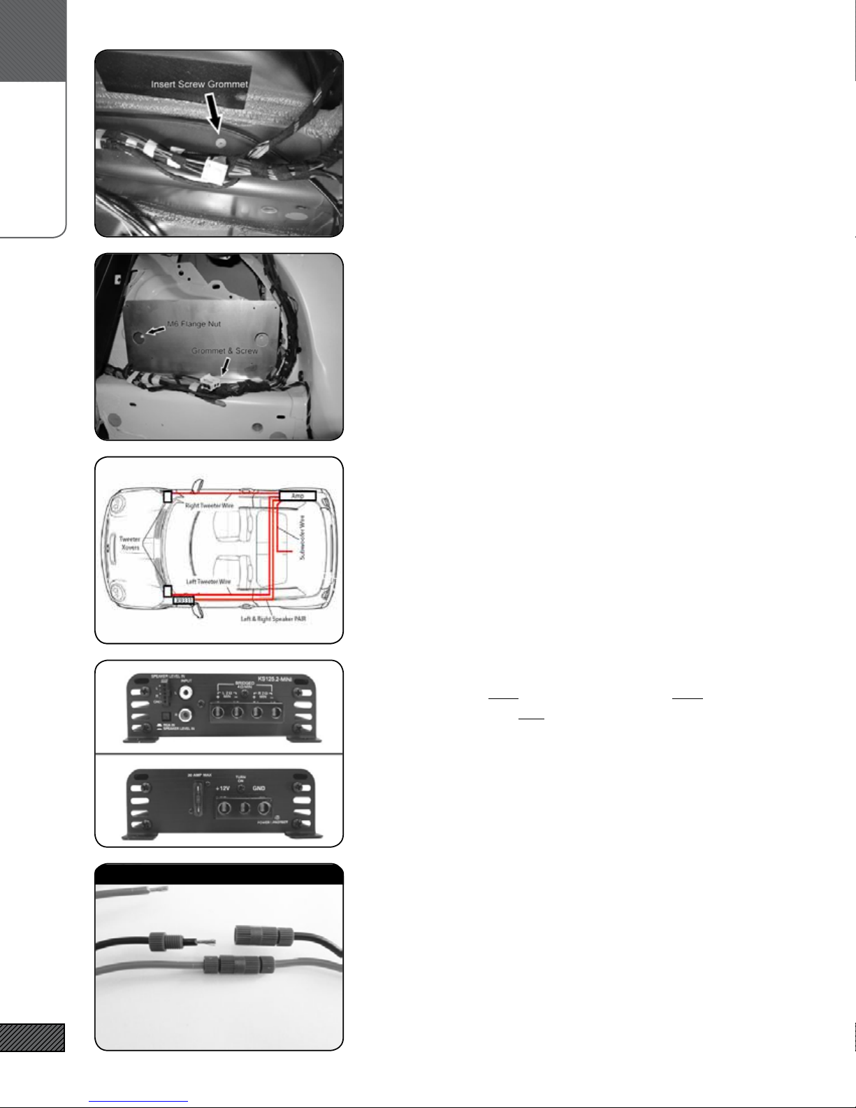
30. INSTALL THE AMPLIFIER BRACKET (PART 1)
Loosen the wire bundle running along the bottom of the right
rear wheel well area. Insert the Screw Grommet into the hole in
the horizontal section of sheet metal as shown. Place the bracket
with rear horizontal hole aligned with the screw grommet and
the forward hole over the threaded stud. You may need to bend
the bracket slightly to get it to t.
31. INSTALL THE AMPLIFIER BRACKET (PART 2)
Fasten the #8 X ½” Screw through the rear hole in the bracket and
into the Screw Grommet. If the Grommet turns, use a straight
pick or small screwdriver inserted into the split in the Grommet
to keep it from turning.
Attach the bracket to the threaded stud protruding through the
hole at the forward end (towards the front of the car) with the M6
nut. A deep socket is helpful for this step.
32. SPEAKER WIRING (OVERVIEW)
The front channels of the ARC amplier drive the front tweeter
and midrange/midwoofer in parallel. The rear channels drive
the subwoofer. The factory HU/Amp continues to drive the rear
ll speakers. In Standard 6 speaker vehicles, the signal wiring
harness feeds the door midrange and midwoofer via the X9331
T-harness. In HiFi/HK equipped vehicles, a separate connection is
made to the factory wiring downstream of the HiFi/HK amplier.
There are separate wires for the tweeters in all vehicles.
33. AMPLIFIER TO SPEAKER OUTPUT CONNECTIONS
Connect BOTH the Left Tweeter wire AND the Left Midrange/
Midwoofer wires to the Left channel of the ARC ampler. Repeat
for the right channel. YOU WILL HAVE TWO WIRES IN EACH OF
THE HOLES.
[SUB ONLY] Connect the Subwoofer wire to the rear channels in
the “bridged” conguration as shown on amp. YOU WILL HAVE
ONE WIRE IN EACH OF THE OUTER HOLES.
NOTE: 2ch amp shown. The 4ch has 2 rows of speaker outputs.
34. HOW TO CONNECT THREADLOCKS
[HIFI/HK ONLY] The Threadlocks will be used in the next steps
for HIFI/HK equipped vehicles. They work like this: Strip 3/8” of
insulation from the wire to be connected. Unscrew one end of
the Threadlock and insert the wire through the end, then tighten.
There should be no exposed wire and the wire should be secured
thightly in the connector. These form a mechanical connection
that is easily reversible and more reliable than a soldered connec-
tion.
[hifi/hk ONLY]

D.
SOUNDSTAGE
13
35. SPEAKER WIRE CONNECTIONS
[HIFI/HK ONLY]
The midrange/midwoofer wires on the HIFI/HK do not pass thru
the X9331 and must be tied in at the factory amplier in the left
side of the luggage compartment. Refer to the chart below. Cut,
strip, and connect the wire to the side coming from the car (NOT
the factory amp!).Check pin assignments (see next step) to con-
rm correct wires - some vehicles have duplicate color pairs!!
36. HOW TO CHECK HIFI/HK PIN NUMBERS
[HIFI/HK ONLY]
Unplug the factory ampler connector by releasing the locking
lever. Gently pry the black plastic housing out to release the lock-
ing tab.
Slide the inner connectors out of the housing. You will see the
pin numbers marked on the housing. Verify with the chart above
.
37. AMPLIFIER POWER & SIGNAL CONNECTIONS
Connect the Power, Ground, and Remote Turn-on Lead wires to
the amplier.
Connect the RCA Interconnects. Set the INPUT selector on the
amp to “RCA” (2ch amp) or “LOW” (4ch amp)
[SUB ONLY] Connect the RCA’s labeled “SUB” to the Rear Inputs of
the amplier.
38. ATTACH AMPLIFIER TO BRACKET
Mount the Amplier to the bracket using the (4) #6 x 3/8” screws.
Use the pre-drilled hole locations. Place the wire bundle (that was
loosened earlier) in the gap between the amp and the sheet metal.
hifi/hk speaker Output CONNeCtiONs
SIGNAL WIRE COLOR PIN CONNECT TO AMP
Front Left ++ Blue w/White Stripe 33 Front Left ++
Front Left -- Blue w/Brown Strip 34 Front Left --
Front Right ++ Blue w/Black Stripe 11 Front Right ++
Front Right -- Bue w/Brown Stripe 12 Front Right --
[hifi/hk ONLY]
[hifi/hk ONLY]

D.
SOUNDSTAGE
14
39. REMOVE DOOR HANDLE TRIM RING
Pull pin (1). Leave trim ring (2) in place, it will come off when you
remove the door panel.
40. REMOVE PUDDLE LIGHT
Pry out Puddle Light (1) from bottom of door. Disconnect and set
aside.
41. REMOVE DOOR PANEL
Remove door panel (1) by pulling rmly inward to release clips
(2). Begin at the bottom rear corner and work your way around.
Use a plastic panel removal tool to help you get started. The Door
Handle Trim Ring will come off with the panel. Set aside with
the pin removed earlier - it will snap on after you replace the door
panel. Be aware of the door lock indicator on the top/rear when
removing the door panel - lift the panel up and over to clear the
indicator!
42. REMOVE MIRROR CONTROL
Carefully pry the Mirror Control (2) up at the bottom rear. Once it
releases wiggle it up and out. Unplug connectors (1) and set aside.
43. MIDRANGE COVER
Pull rmly up and in on the Midrange Cover (1) while pressing
inward at the locations of the tabs (2). It is better to pull rmly
than to try to pry at the tab locations. Give it a rm pull, it will
pop free!

D.
SOUNDSTAGE
15
44. REMOVE DOOR SPEAKERS
Remove the woofer mounting screws (1) with a Torx T-25. Unplug
the speaker connector (2). Repeat for the door midrange.
Keep the Torx screws - they will be used to mount the new speak-
er adapters.
45. REMOVE ARMREST COVER & TRIM
Remove Armrest Cover (1) by levering up the edges of the trim in
the directions indicated by the arrows.
Remove the trim cover (2) by releasing the two Torx-25 screws at
either end.
46. MIDRANGE/MIDWOOFER (OVERVIEW)
The Midrange/Midwoofer crossover network (1) installs in the cav-
ity behind the door armrest cover. The wiring harness connects
to the factory midrange connector (blue). The wiring harness is
routed behind the armrest trim and through the hole at the back
of the midrange cover to the factory connector and the midrange
driver. The wire for the woofer continues behind the midrange,
down and through the rubber grommet and on to the back of the
midwoofer.
47. MIDRANGE/MIDWOOFER WIRE HARNESS
The wiring harness for the speaker and crossover connections to
the door speakers has been pre-fabricated. Connector (1) will plug
directly into the factory midrange connector. The 18” branch (3)
connects to the midrange driver. The 36” branch (4) connects to
the woofer. The stripped ends (2) connect to the crossover in the
armrest.
48. ROUTE & CONNECT WIRE HARNESS
Route all wires through the opening (1) at the rear of the mid-
range cavity. Connect the blue connector to the factory midrange
connector. Leave the midrange wire in the midrange cavity. Con-
tinue running the woofer wire behind the midrange cavity, then
out and down to the rubber grommet (2). Using a utility knife, cut
a small slit in the grommet and run the woofer wire through and
into the door cavity. Be certain all wires are clear of any moving
parts or obstructions!

D.
SOUNDSTAGAE
16
49. CROSSOVER CONNECTIONS
Connect the stripped wires ends to the crossover board. The
branch from the blue connector connects to the “IN”. The mid-
range branch connects to “M”, and the woofer branch connects to
“W”. Red is + and Black is - for all three.
[NOTE: Xover board shown with foam cover removed for clarity]
50. MOUNT MIDRANGE & MIDWOOFER
Mount the Woofer Adapter to the door with the factory Torx
screws removed earlier. Connect the woofer wiring, making sure
the connectors lock to the speaker tabs. Use wire ties to ensure
that the woofer wiring is clear of the window mechanism! Mount
the woofer with the #8 x 1/2” black oxide screws.
Repeat the process for the Midrange, using the #6 x 3/8” screws.
51. TWEETER INSTALLATION (OVERVIEW)
The Soundstage Tweeters install directly into the factory tweeter
mounts on the A-Pillar trim (the trim at either side of the wind-
shield). The tweeter crossover networks install in a small com-
partment on either side of the dashboard. The crossover input
connects to the tweeter wire from the amp and the 18” tweeter
pigtail connects to crossover to the tweeter.
[6SPK ONLY] The new A-pillar trim is included
52. REMOVE A-PILLAR TRIM
Carefully lever/pry out screw cap cover (1). Remove the T-20 Torx
screw underneath. Loosen the door seal (4) to gain access to the
edge of the trim piece (3). Pull inward to release clips (2). Discon-
nect the tweeter wire and remove the the trim piece.
[6SPK ONLY] You will not be reusing this trim piece
[HIFI/HK ONLY] You WILL be reusing this trim piece.
53. REMOVE EXISTING TWEETER
[HIFI/HK ONLY]
Release tabs (1) and remove tweeter (2). Unclip capacitor and wire
(3) and remove.
[hifi/hk ONLY]

D.
SOUNDSTAGE
17
54. REMOVE/REPLACE TWEETER BADGES
[2010+ HK ONLY]
Remove the “Harmon/Kardon” tweeter badge by prying up gently
with a at screwdriver. You need to insert the blade into the thin
gap between the badge and the backing plate, not between the
backing plate and the grill material. Replace with the adhesive
Integral Audio badge by removing the backing and afxing in the
recess in the tweeter grille.
55. INSTALL TWEETER
Press the new tweeter squarely and rmly into the housing until
it locks into place. The “I” logo should be vertical.
NOTE: On some cars the tweeter mount may be warped, making
a very tight t. If you can’t get all the tweeter latches to lock, use
a small dab of cyanoacrylate (superglue) at the tab location.
56. OPEN DASHBOARD SIDE COMPARTMENT
Using a panel removal tool, lever open the plastic cover on the
side of the dashboard. Run the tweeter wire coming from the
amp up the side of the door jam and into this compartment.
57. INSTALL & CONNECT TWEETER CROSSOVER
Connect the tweeter wire from the amp to the “IN” terminals on
the tweeter crossover. Connect the 18” Tweeter Pigtail to the “T”
outputs. Route the pigtail up to the base of the A-pillar for con-
nection to the tweeter. Place tweeter crossover (1) into compart-
ment.
58. REPLACE A-PILLAR
Connect the tweeter wire pigtail to the tweeter (4).Replace the
A-pillar trim (1). Take care to ensure that the tabs (3) and clips (2)
align with their corresponding holes on the vehicle, and that the
clear rubber sleeves are protecting the metal tweeter tabs. The
tabs (3) can be a little tricky - it helps to use a panel tool between
the trim and the windshield to force the tabs inward and into the
holes. Do not replace the screw and screw cover yet (wait until
after testing!)
[2010+ hifi/hk ONLY]

E.
SUBWOOFER
18
59. REPEAT FOR THE RIGHT SIDE
Repeat all of this section for the other side of the vehicle. Obvi-
ously, you can omit the steps relating to the mirror switch!
60. SUBWOOFER INSTALLATION
This entire section applies only to the subwoofer installation. If
you are not installing the subwoofer system please proceed to the
next section.
61. INSTALL NEUTRIK SPEAK-ON PLUG
Split and strip the other end of the 10ft length of Subwoofer
Speaker wire. Identify the cable-mount portion of the Neutrik
connector. Remove the blue portion and strain relief, and insert
the speaker wire through both. Loosen the terminal clamping
screws, insert each wire (observing the polarity markings on the
connector), and tighten the screw. Screw the blue portion onto
the housing.
62. ATTACH THE MOUNTING BRACKETS
Align the Mounting Brackets over the pre-drilled pilot holes and
attach using the (8) #10 screws.
63. THREADED INSERTS (OVERVIEW)
Self-Sealing Threaded Inserts are used to secure the enclosure
to the vehicle. It is important that you follow these installation
steps carefully and completely. An extra Insert is provided in
case you run into trouble.
SEE PREVIOUS IMAGES

E.
SUBWOOFER
19
64. MARK FOR THREADED INSERT PLACEMENT
Temporarily replace the Wheel Arch Trim Panels and Rear Sill, if
previously removed. Center the enclosure in the boot. Using a
center punch (or marker), mark the center of the mounting brack-
et hole in the sheet metal below. Keep the hole at least 3/8” away
from the edges of the raised area of the sheet metal. Cut a notch
in the carpet edge if necessary. Mark the center with a marker or
center punch.
65. INSTALL THREADED INSERTS (PART 1)
Using a 7/16” bit (NOT a ½” bit!), drill holes in the 2 positions
marked on the boot oor. Do not let the drill bit penetrate more
than ¼” through the sheet metal. You may nd it helpful to use a
cut-to-length wood block as a stop for the drill. It is important to
drill the holes EXACTLY where they were marked.
Remove any metal burrs - the hole must have clean edges.
66. INSTALL THREADED INSERTS (PART 2)
Using a utility knife, carefully trim the PVC jacket out of the
center of the Self-Sealing Threaded Inserts as shown. Insert the
1” Hex Bolt through the Installation Tool. Then thread the 1” Hex
Bolt into the Threaded Insert. Be sure the “nubs” on the Instal-
lation Tool face the top of the Threaded Insert. These “nubs” are
what grip the Insert and prevent it from turning during installa-
tion.
67. INSTALL THREADED INSERTS (PART 3)
Insert the Threaded Inserts into the holes drilled in the previ-
ous step. Keep the Insert vertical and keep the head of the Insert
ush against the sheet metal and carefully tighten the bolt by
hand with a wrench (do not use a powered tool of any kind) until
you begin to feel resistance and the insert is secure. Take your
time - do not over-tighten. Remove the 1” Hex bolt. If you have
trouble with an Insert, you can remove it by partially unthreading
the 1” Hex bolt and tapping it with a hammer.
68. WIRING & TERMINAL
Connect the subwoofer internal wiring harness to the back of the
Neutrik Speak-on connector (observing correct +/- polarity). Place
the Speak-on gasket over the connector, thread the wire through
the mounting hole, and mount the Speak-on connector using the
(2) #4 x 1/2” screws..

E.
SUBWOOFER
20
69. MOUNT THE SPEAKER
Connect the wiring harness to the subwoofer terminals. Mount
the speaker with the #10 x 1” Black Pan Head Screws, using the
pre-drilled pilot holes. Tighten the screws in a “star” pattern,
go slowly and take care not to strip them. Make sure the speaker
ange is ush against the enclosure – the gasket on the back of
the speaker ange MUST make an airtight seal.
70. MOUNT THE FLOOR SUPPORTS (PART 1)
The 3 front supports are assembled with one Rubber Stand-off,
one Cup Washer, and one #10 x 1.5” Pan Head Screw. The rear
supports are twice as tall and are assembled with two Stand-offs
(stacked), one Cup Washer, and one 2.5” Pan Head Screw.
NOTE: The Stand-offs may have warped in transit. To get them to
stack cleanly, wrap a few turns of electrical tape around them at
the seam. Remove after installation.
71. MOUNT THE FLOOR SUPPORTS (PART 2)
Mount the Stand-offs in the pre-drilled pilot holes as indicated.
IMPORTANT: Tighten the screws until the metal Washer is re-
cessed below the top of the Rubber Stand-off, providing a soft
surface for the False Floor. If this is not done, the oor will rattle
on the washer/screw-head.
72. INSTALL THE ENCLOSURE
Place the enclosure back into the boot. Connect the Speak-on
connector. Insert the Rosette Thumbscrews through the Mount-
ing Brackets and screw into the Threaded Inserts.
NOTE: We recommend coating the threads of the Rosette Thumb-
screws with grease to keep them operating smoothly and avoid
corrosion.
73. HOW TO REMOVE THE FALSE FLOOR
The False Floor Panel slides through the hatch opening and rests
on the oor supports. To remove, simply push down on the edge
near the rear seat backs, lift, and remove – clean, simple, easy!
This manual suits for next models
1
Table of contents
Other Integral Audio Subwoofer manuals

Integral Audio
Integral Audio 1100S User manual

Integral Audio
Integral Audio 81S User manual

Integral Audio
Integral Audio SoundStage + Subwoofer System User manual

Integral Audio
Integral Audio PHANTOM User manual

Integral Audio
Integral Audio 1101S User manual

Integral Audio
Integral Audio PHANTOM User manual

Integral Audio
Integral Audio 1101S User manual

Integral Audio
Integral Audio 1101S User manual