Integral Audio 1101S User manual

IMPORTANT
!
• ReadthisInstallationGuidecompletelybeforebeginningtheinstallation.
• Thisisaguide–yourvehiclemayvary.ALWAYScheckbehindpanels&
componentsbeforedrilling,cutting,orscrewingintoanypartofavehicle.
Contents
INSTALLATION GUIDE
MINI COOPER
MODEL 1101S SUBWOOFER SYSTEM
DIY
SKILL LEVEL
REQUIRED
35
INSTALLATION
DIFFICULTY
OUT OF
4
INSTALLATION
TIME
Hrs
R57 Convertible (2009+)
R56 JCW Hardtop (2007-2009)
R58 Coupe (All Years)
R59 Roadster (All Years)
OVERVIEW.................................................................................... 2
BEFOREYOUBEGIN!................................................................... 2
WHAT’SINTHEBOX.................................................................... 3
TOOLSYOUWILLNEED.............................................................. 5
INSTALLATION:
A.PrePtheVehicle.................................................................. 6
B.runthePower&Groundwires.......................................... 7
c.siGnAlwirinG....................................................................... 8
d.MountAMPlifier&connectwirinG...................................... 9
e.instAlltheenclosureMounts............................................ 10
f. PreP&instAlltheenclosure............................................ 11
G.testinG&recoMMendedinitiAlsettinGs............................. 12
TIPS&TUNING........................................................................... 13
TROUBLESHOOTING................................................................. 13

2|IntegralAudio|InstallationInstructions Continuedonnextpage...
• reAdtheseinstructionscoMPletelyfroMstArttofinishBe-
foreGoinGneArthecAr!!
• instAllAtionVAriesdePendinGonVehicleModelAndequiPMent.
MAkesureyouhAVeProPerlyidentifiedyourVehicleAndnote
whichinstAllAtionstePsAPPly.stePslABeledAsfollows:
- [r5Xonly]APPlyonlytothesPecificModellisted.MAke
sureyouknowwhAtdesiGnAtionyourVehicleis.
- ifnoVehicledesiGnAtionislisted,theinstAllAtionsteP
APPliestoAllVehicles
• disconnecttheneGAtiVeBAtteryterMinAl
• GAtherAllrequiredtools
• lAyout&identifyAllcoMPonents&hArdwAre.MAkesureyou
hAVeAllthecoMPonentsrequiredforyourinstAllAtion.
• note:donotPutthekeyfoBintheiGnitioniftheelectricAl
connectortoeitherfrontseAtdisconnected!!youwillsetoff
thesrs/AirBAGliGhtAndwillhAVetohAVeitresetBythedeAler!
• note:eAchkitMAyAPPlytoMorethAnoneVehicleModelAnd
MAyincludeeXtrAiteMs.disreGArdAnyiteMsnotMentionedin
theinstructionsforyourVehicle.
• note:donotdeViAtefroMtheseinstructionsortheincluded
hArdwAre.eVerycoMPonentofthissysteMhAsBeencArefully
selectedByourenGineers.fAiluretofollowtheseinstruc-
tionsorcorrectlyidentifyAndusethesuPPliedhArdwAreMAy
resultinPoorPerforMAnceAndPossiBlesAfetyhAzArds.ifin
douBt,contActusAndwewillBehAPPytohelPyou.
Overview Before You Begin!
thisGuidecoVersinstAllAtionoftheModel1101ssuBwoofersysteMin
2009&uPMinicooPerr57conVertiBles,r58couPes,r59roAdsters,
Andr56hArdtoPsthAtdonothAVethesMAllstorAGecoMPArtMentonthe
riGhtsideoftheBoot.
thesuBwooferenclosureinstAllsintheflooroftheluGGAGecoMPArt-
Ment(AkAthe“Boot”).thesuBAMPlifierinstAllsunderthePAssenGer’s
seAt.AreMoteleVelcontrolinstAllsAtthedAshforon-the-flysuB-
wooferAdjustMent.
Power&GroundwiresAreconnectedtotheBAtteryAndAchAssis
GroundPointAndrundownthePAssenGersideoftheVehicleAndtotheAM-
Plifier.theAudiosiGnAlAndAMPlifierturn-onsiGnAlcoMefroMtheX9331
&X15connectorsintheleftfootwell.thesiGnAlwirinGisrunfroMthe
leftfootwelltothedAsh-MountedreMoteleVelcontrolAndthentothe
suBAMPlifier.

3|IntegralAudio|InstallationInstructions Continuedonnextpage...3|IntegralAudio|InstallationInstructions Continuedonnextpage...
What’s In The Box
2
24
28
26
25
11
98
10
3534
37273676543
15
14
13
*selectcoMPonentsforidentificAtion-notAllcoMPonentsshownBelow
iMAGesnottoscAle
I. Model1101SSubwooferencloSure
II. SbAcouStIcS10”Subwoofer
III. ArcAudIoKS125.2MInIAMplIfIer
IV. fAlSefloorpAnel
V. SubwooferencloSureHArdwAreKIt
1. terMinAlcuPw/GoldBindinGPosts
2. #10X2.5”PAnheAdscrew(3)
3. #10X1.5”PAnheAdscrew(6)
4. ¼”X1”heXheAdBolt
5. #10X1”BlAckPAnheAdscrew(8)
6. #10X¾”PAnheAdscrew(8)
7. #6X¾”BlAckPAnheAdscrew(4)
8. threAdedinsert(3)
9. threAdedinsertinstAllAtiontool
10. cuPwAsher(6)
11. ruBBerstAnd-off(9)
12. suBwooferwirinGhArness
13. suBwooferMountinGBrAcket(2)
14. rosettethuMBscrew(2)
VI. AMplIfIerInStAllAtIon&wIrIngKIt
15. X9331wirinGhArness
16. PAclc1reMoteleVelcontrol
17. PreMiuMrcAinterconnects
18. cABleties(5)
19. AlcoholPrePwiPe(3)
20. 3MdouBle-sidedfoAMtAPe
21. 3MelectricAltAPe
22. BAnAnAPluGs–1PAir[red&BlAck]
23. wAterProofAGufuseholder
24. 30AMPAGufuse(2)
25. #6X½”heXwAsherscrew,stAinless(3)
26. 5/16”GoldrinGterMinAl–1PAir[red&BlAck]
27. 8AwGredultrAfleXPowerwire(15feet)
28. 8AwGBlAckultrAfleXGroundwire(7feet)
29. 18AwGwhitereMoteturn-onwire(15feet)
30. 16AwGred/BlAcksPeAkerwire(8+2feet)
31. under-seAtAMPlifierMountinGPlAte
32. under-seAtMulti-fuctionBoXcoVer

4|IntegralAudio|InstallationInstructions Continuedonnextpage...4|IntegralAudio|InstallationInstructions Continuedonnextpage...
Tools You Will Need
A. wIreStrIpper/crIMper
b. torxbItS:
• t50
c. electrIcdrIll
d. drIllbItS:
• 1/8”
• 7/16”
e. wrencHeSorSocKetS:
• 7/16”
• 8MM
• 10MM
• 19MM
f. 3MMAllenwrencH
g. electrIcIAn’SwIrefISH
H. ScISSorS
I. lIgHterorSMAlltorcH
J. utIlItyKnIfe
K. pencIlorfIne-tIpMArKer
l. plIerS
M. pAnelreMoVAltoolS
n. pIcK&HooKSet
o. centerpuncH
p. MAgnetIcpArtStrAy
P
C
G
H
L
A
I
M
E
N
K
O
D
J
B
F
iMAGesnottoscAle

5|IntegralAudio|InstallationInstructions Continuedonnextpage...
1. reMoVepASSengerSeAt
Slide the seat forward. Using a Torx T-40, remove the
two screws holding the rear of the seat (1). Slide the
seat backward and repeat for the two front screws.
A. PREPVEHICLE
7. reMoVeleftdoorSIlltrIM(pArt3)
[Seat shown removed for clarity]
Remove the door seal over the entire length of the
right door sill by lifting it up and off. Pull up/loosen
the rubber door seal gasket along the length of the
door. Pull Door Sill Panel (2) inward, releasing clips
(3). This requires a rm pull at each of the clip loca-
tions. Remove the small trim piece (1) by pulling it
toward the rear of the vehicle, releasing spring clip.
5. reMoVeleftdoorSIlltrIM(pArt1)
Using a Torx T-50 bit, remove the seat belt screw (1)
where it passes through the rear of the door sill trim.
3. reMoVepASSengerSeAt(pArt3)
If present, remove the plastic panel under the seat.
2. reMoVepASSengerSeAt(pArt2)
Tilt the seat back. Disconnect the airbag wiring under
the seat by pulling the black slide catch on the side
of the yellow plug. Disconnect the seat heater wiring
if equipped. DO NOT put the key FOB in the ignition
while this plug is disconnected. Remove the seat
from the vehicle.
6. reMoVeleftdoorSIlltrIM(pArt2)
Remove metal seat belt bushing (1) if not removed
in the previous step. Pull Rear Side Trim Panel (4)
in, releasing clip (3) and freeing tab of Door Sill (2)
located behind Side Panel (4).
4. reMoVedrIVerSeAt
[R57 with HIFI/HK ONLY]
Repeat the previous steps to remove the Driver seat.
SeePrevious
Images
8. reMoVetHerIgHtdoorSIlltrIM
Repeat the previous three steps for the Right Side of
the vehicle.
SeePrevious
Images

6|IntegralAudio|InstallationInstructions Continuedonnextpage...
9. releASefrontoftHereArSeAtbottoM
[R55 & R56 ONLY]
Pull up rmly on the front of the edge of the rear
seat bottom to release. This will allow you access to
under the carpet in later steps.
15. feedpowerwIreIntocAbIn
Cut the end off the spare wiring nipple at the wiring
bushing adjacent to the batter. Feed the 8AWG Red
Power Wire through the spare wiring nipple and into
the cabin. From inside the vehicle, locate the wire
coming in. Feed the wire around the fuse box and
along the Right Door Sill.
16. groundwIre
Locate the Common Ground point under the Right
Door Sill. Remove the nut with a 10mm socket. Strip
the end of the Ground wire, crimp the black 5/16”
Gold Ring Terminal to the end, and attach to the
Common Ground point.
NOTE: On some vehicles the common ground is
located a bit further forward. Enough ground wire is
included to reach either location.
14. InStAllfuSeHolder(pArt2)
Mount the Fuse Holder to the plastic bulkhead next
to the battery using 2 of the #6 x ½” Stainless Hex
Washer Head Self-tapping screws. Use a Center
Punch to form a starting hole or pre-drill the holes
with a 1/8” bit.
Remove the auxiliary nut on the battery post with a
19mm socket and attach the Ring Terminal of the 18”
length. Do not install the fuse into the holder yet.
13. InStAllfuSeHolder(pArt1)
Cut approx 18” from the Power Wire to run from the
fuse holder to the battery. Strip the end of the Power
Wire and both ends of the 18” length. Crimp the red
5/16” Gold Ring Terminal to one end of the 18” length.
Remove one end cap of the fuse holder and insert
the other end of the 18” length, then secure the gold
terminal end of the fuse holder onto the wire with a
3mm Allen wrench. Repeat the process to attach the
other section of wire.
12. reMoVetHru-wAllcoVer
OPTIONAL: The next few steps are easier if you
remove the battery.
Locate the thru-wall bushing behind the battery. Us-
ing a at screwdriver, release the indicated retain-
ing tabs then remove the plastic thru-wall cover to
expose the thru-wall opening.
B. POWER&GROUNDWIRING
10. power&groundwIrIng(oVerVIew)
The 12V+ wire runs directly from the battery to the
new amplier that installs under the passenger seat.
An inline fuse is installed at the battery.
The Ground wire runs from the amplier to one of the
factory-installed common ground points along the
door sill
11. reMoVerIgHtcowlpAnel
Open the Bonnet (aka the hood!). Remove the black
plastic Cowl covering the battery by releasing nuts (2)
and (3) with a 10mm socket. Loosen & remove cowl.
NOTE: When replacing the cowl, be sure the seal (1)
is seated properly and that the secondary tab of the
cowl (4) is inserted into the plastic channel (5) that
attaches to the bottom of the windshield.

7|IntegralAudio|InstallationInstructions Continuedonnextpage...
17. SIgnAlwIrIng(oVerVIew)
The factory audio signal is pulled from the X9331
connector in the driver-side footwell, described below.
The included custom T-harness plugs into each side
of the factory connector. RCA interconnects are run
to the to the remote-level control for the subwoofer (if
equipped) and to the amplier. The power-on signal
for the amplier is obtained from pin 1 of the X15
connector.
22. reMoVefootwellpAnel
Remove the panel next to gas pedal by releasing
the Torx T-25 screws and pulling the panel out and
towards the rear of the vehicle.
21. MountreMoteleVelcontrol
Mount the Remote Level Control below the toggle
switches. Wipe the surface with the Alcohol Prep Pad
before applying.
Do a dry-run to check the placement and be sure
you know exactly where you’d like the control. You
will nd that you can place it more toward the front of
the recess for easier access, or toward the rear for a
more hidden look.
20. reMoteleVelcontrol
[SUB ONLY]
Attach the 3M VHB double-sided adhesive (this is
the green 3in length) to the top of the Remote Level
Control. Trim extra length from the VHB, if neces-
sary. Wipe the surface with one of the Alcohol Prep
Pad before applying.
19. connectx9331t-HArneSS
Unplug the X9331 connector and connect the T-
Harness. The RCA Jacks are the OUTPUT from the
factory stereo - in later steps they will be connected
to the INPUT on the remote level control [sub only]
and the amplier. Red = Right Channel, White = Left
Channel. Both reds and both whites carry the same
signal and are interchangable. The stripped wire
ends are SPEAKER INPUT and will be connected to
the amplier OUTPUT. The left channel is labeled.
18. AcceSSx9331&x15connectorS
Locate these connectors in the left footwell. The
X9331 is behind and attached to the larger X15.
Remove both by twisting counter-clockwise ¼ turn
and pulling outwards. Separate the X9331 from the
X15 by releasing the locking tabs on the connector
joining them.
23. connectreMoteleVelcontrol
Feed the Remote Level Control leads under the bot-
tom edge of the center stack and around to the are
under the panel you just removed.
Connect the 3FT RCAs to the “IN” leads on the Re-
mote Level Control, and one of the 17FT RCAs to the
“OUT” leads. Wrap the exposed metal of the RCAs
with electrical tape!
24. routercAInterconnectS
[SUB ONLY]
Pull rmly on the top of the plastic panel under the
steering wheel to release the top edge of the panel.
Feed the RCAs along and under the knee bolster
and secure with cable ties. Be sure the wires are
clear of any moving parts or pinch points.
C.SIGNALWIRING

8|IntegralAudio|InstallationInstructions Continuedonnextpage...
25. x9331SIgnAlconnectIonS
Connect the 3FT RCA from the “IN” on the Remote
Level Control to one red/white pair of RCA jacks on
the X9331 harness. Wrap the exposed metal of the
RCAs with electrical tape!
All exposed metal of RCA and/or wire ends MUST be
taped off and isolated from each other!!
31. AttAcHAMplIfIerMountIngplAte
Attach the amplier to the mounting plate using the
#6 x 3/8” screws. Cut strips of the 3M Double-Sided
Foam Mounting tape and afx one side to the back
of the amp mounting plate and any original equip-
ment from the underseat compartment. Arrange all
components so that they t. Clean all components
and the sheet metal with an Alcohol Prep Pad prior to
attaching the Foam Mounting Tape.
32. AMplIfIerpower&SIgnAlconnectIonS
Strip and connect the Power, Ground, and Remote
Turn-on Lead wires to the amplier.
Connect the RCA Interconnects. Set the Signal input
selector on the amp to “RCA”. Refer to the Amp
manual if needed. Do not mount or cover the amp
yet - you will want it uncovered for settings adjust-
ments.
30. reMoVetHeplAStIctub
[FOR VEHICLES WITH EXISTING COVER]
Remove the plastic tub liner from the compartment.
Detach any equipment mounted to it.
DO NOT remove or remount the DSC module (see
image)
29. trIMcArpetforcoMpArtMentcoVer
[FOR VEHICLES WITH CARPET UNDER SEAT]
Lay the Amplier Compartment Cover on the area
underseat. Note where the carpet needs to be cut
and mark with tape. Cut the carpet and foam backing
with a utility knife. Cut CAREFULLY - there are wires
running along the front edge of the compartment.
The carpet should be cut SMALLER than the cover or
there will be exposed area. Use the driver’s side as a
guide. Notch the carpet in the mounting screw areas.
28. AMplIfIerMountIng(oVerVIew)
The amplier mounts in the compartment under the
passenger seat. If your vehicle does not have a com-
partment with cover under the seat, one has been
included in your kit. You will cut the carpet, remove
the foam block inside, and then mount the amp.
27. runSIgnAlwIrIngtoAMp
Beginning in the left (driver’s) side footwell, run the
RCAs and remote turn-on along the door sill, and
under the carpet in the rear seat footwell area.power/
ground wires. Be sure the wiring is clear of all pinch
points, including the Seat Belt screw.
AVOID PLACING SIGNAL WIRING DIRECTLY
ADJACENT TO OR TOUCHING OTHER WIRING
BUNDLES!
26. reMoteturn-onwIre
Identify the solid black wire coming out of pin 1 of the
X15 connector (see step 21). Strip 3/8” of insulation
from one end of the 18AWG White Turn-on Lead wire.
Unscrew both ends of the Posi-tap (the Posi-tap has
a hole in only one end, the Posi-lock used later has a
hole in each end. Slip the “U”-shaped bottom around
the signal wire to be tapped. Carefully thread the
body of the Posi-tap onto this and tighten rmly. Be
sure not to cross-thread the Posi-tap.
D.AMPLIFIERINSTALLATION&SUBWOOFERWIRING

9|IntegralAudio|InstallationInstructions Continuedonnextpage...
39. tHreAdedInSertS(oVerVIew)
Self-Sealing Threaded Inserts are used to secure
the enclosure to the vehicle. It is important that you
follow these installation steps carefully and com-
pletely. An extra Insert is provided in case you run
into trouble.
40. InStAlltHreAdedInSertS(pArt1)
Using a 7/16” bit (NOT a ½” bit!), drill holes in the 2
positions marked on the boot oor. Do not let the drill
bit penetrate more than ¼” through the sheet metal.
You may nd it helpful to use a cut-to-length wood
block as a stop for the drill. It is important to drill the
holes EXACTLY where they were marked.
Remove any metal burrs - the hole must have clean
edges.
38. AttAcHtHeMountIngbrAcKetS
Remove the enclosure. Align the brackets with the
lines marked in the previous step. Place the bottom
of the bracket approx 1/4” above the bottom edge
of the enclosure. Attach the bracket with the #10 x
¾” Pan Head Screws. Replace the enclosure and
conrm hole locations are correctly market. Remove
the enclosure.
37. MArKforbrAcKetAndtHreAdedInSert
Center the enclosure in the boot. Place a Mounting
Bracket on each side with the single-hole centered
over the raised area of the boot oor. Keep the hole
at least 3/8” away from the edges of the raised area
of the sheet metal. Cut a notch in the carpet edge if
necessary. Mark the center with a marker or center
punch. Mark the location of the vertical sides of the
bracket against the enclosure with a pencil.
36. SubwooferbAnAnAplugS
Split and strip the end of the Subwoofer Speaker
wire. Attach the Banana Plugs to the other end by
loosening the 3mm Allen screw, inserting the wire,
and tightening the screw.
34. runSubwooferwIre
[R58 & R59 ONLY]
Loosen the edge of the panel by removing the three
friction clips (1).
35. runSubwooferwIre(pArt2)
[R58 & R59 ONLY]
Lift up the rear quarter panel interior trim exposing
the area underneath. Using the electrician’s wire sh,
sh the subwoofer wire through the area indicated.
Run the wire under the trim covering the cross-beam
and exit it at the center.
33. runSubwooferwIre
[R57 & R56 JCW ONLY]
Run the speaker wire for the subwoofer to the boot.
Begin at the amp, run the wire along the rear side
panel (tucking it underneath the panel), and then
under the trim covering the cross-beam at the front
of the boot area. Exit the wire at the center of the
cross-beam.
E. INSTALLTHESUBWOOFER

10|IntegralAudio|InstallationInstructions Continuedonnextpage...
41. InStAlltHreAdedInSertS(pArt2)
Using a utility knife, carefully trim the PVC jacket out
of the center of the Self-Sealing Threaded Inserts as
shown. Insert the 1” Hex Bolt through the Installation
Tool. Then thread the 1” Hex Bolt into the Threaded
Insert. Be sure the “nubs” on the Installation Tool
face the top of the Threaded Insert. These “nubs” are
what grip the Insert and prevent it from turning during
installation.
47. InStAlltHeencloSure
Place the enclosure back into the boot. Connect
the Banana Plugs to the Terminal Cup. Insert the
Rosette Thumbscrews through the Mounting Brackets
and screw into the Threaded Inserts. If you made a
mistake drilling the holes and the Thumbscrews do
not line up, drill larger holes in the mounting brackets.
NOTE: We recommend coating the threads of the
Rosette Thumbscrews with grease to keep them
operating smoothly and avoid corrosion.
48. HowtoreMoVetHefAlSefloor
[R57 & R56 JCW ONLY]
The False Floor Panel slides through the hatch
opening and rests on the oor supports. To remove,
simply push down on the edge near the rear seat
backs, lift, and remove – clean, simple, easy!
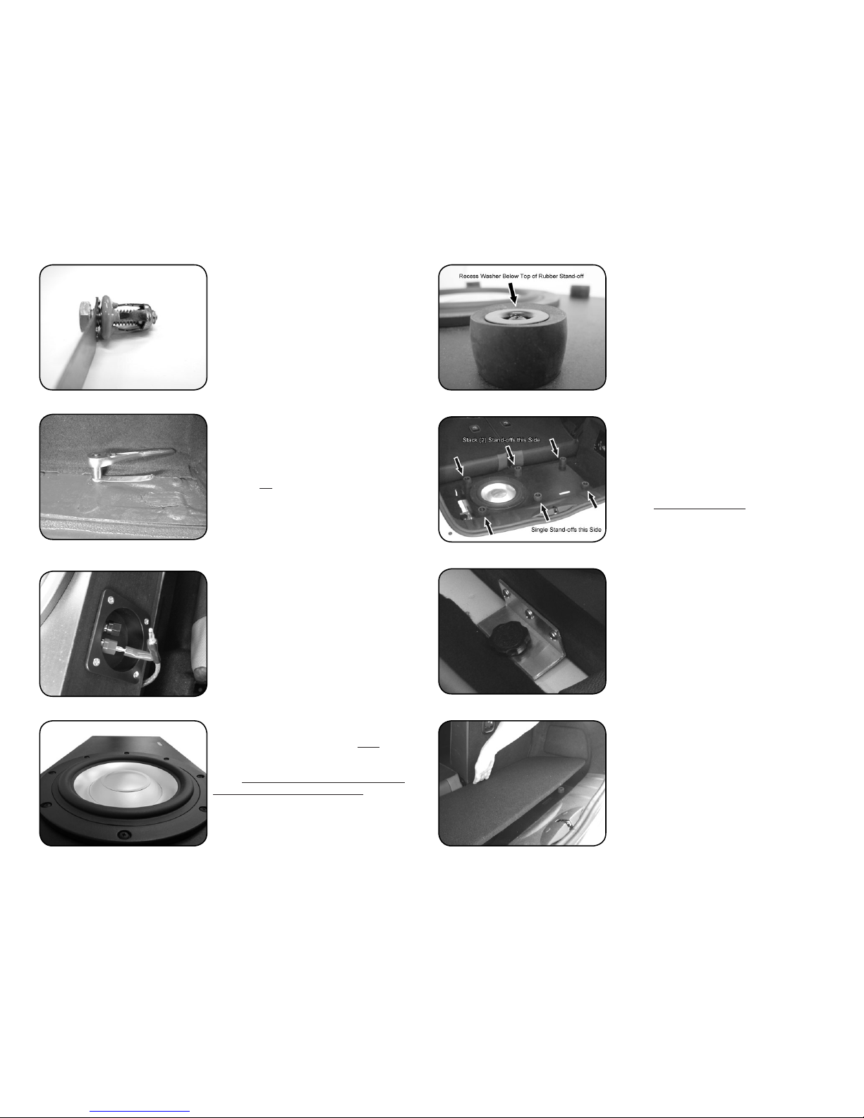
46. MounttHefloorSupportS(pArt2)
Mount the Stand-offs centered approx 2” in from
the edges of the enclosure. Mark and drill 1/8” pilot
holes. Attach the supports with the Screws and Cup
Washers.
IMPORTANT: Tighten the screws until the metal
Washer is recessed below the top of the Rubber
Stand-off, providing a soft surface for the False Floor.
If this is not done, the oor will rattle on the washer/
screw-head.
45. MounttHefloorSupportS(pArt1)
The 3 front supports are assembled with one Rubber
Stand-off, one Cup Washer, and one #10 x 1.5” Pan
Head Screw. The rear supports are twice as tall and
are assembled with two Stand-offs (stacked), one
Cup Washer, and one 2.5” Pan Head Screw.
NOTE: The Stand-offs may have warped in transit.
To get them to stack cleanly, wrap a few turns of
electrical tape around them at the seam. Remove
after installation.
44. MounttHeSpeAKer
Mount the speaker with the #10 x 1” Black Pan Head
Screws. The speaker is a snug t - tap it in with a
rubber mallet until the gasket ange contacts the
bafe. Tighten the screws in a “star” pattern, go
slowly and take care not to strip them. Make sure the
speaker ange is ush against the enclosure – the
gasket on the back of the speaker ange MUST make
an airtight seal.
43. wIrIng&terMInAlcup
Connect the subwoofer to the terminal cup using the
subwoofer connection harness. The .25” terminals
connect to the subwoofer, the .205” terminals connect
to the terminal cup.
Mount the Terminal Cup using the (4) #6 x ¾” Black
Pan Head Screws.
42. InStAlltHreAdedInSertS(pArt3)
Insert the Threaded Inserts into the holes drilled
in the previous step. Keep the Insert vertical and
keep the head of the Insert ush against the sheet
metal and carefully tighten the bolt by hand with a
wrench (do not use a powered tool of any kind) until
you begin to feel resistance and the insert is secure.
Take your time - do not over-tighten. Remove the 1”
Hex bolt. If you have trouble with an Insert, you can
remove it by partially unthreading the 1” Hex bolt and
tapping it with a hammer.

11|IntegralAudio|InstallationInstructions Continuedonnextpage...
49. HowtoreMoVetHeencloSure
To remove the enclosure, simply disconnect the
speaker wire, unscrew the Rosette Thumbscrews,
and remove.
WARNING: Try not to allow the Banana Plug connec-
tors to short (touch each other) while the system is
energized. The amp has short circuit protection and
will temporarily shut down if shorted.
54. AMplIfIerSettIngS(HIfI-equIppedVeHIcleS)
Gain: 75% (see ARC manual)
Output: LOW (low-pass crossover)
Crossover: 60 Hz
Bass Boost: 0 [THIS MUST BE ZERO!!]
Input: RCA In (button should be OUT)
Factory Radio Bass Level: -2
53. recoMMendedInItIAlSettIngS
The following steps list initial recommended settings.
Use these settings as a starting point and adjust from
there.
IMPORTANT: Depending on the source input/
material the head unit is capable of delivering volt-
ages that can drive the amp to clipping and damage
the speakers and/or subwoofer - excercise caution
and listen for signs of distortion or distress at high
volumes, especially with overly synthsized or bass-
intensive music.
F. TESTING&RECOMMENDEDINITIALSETTINGS
55. AMplIfIerSettIngS(H/K-equIppedVeHIcleS)
Gain: 90% (see ARC manual)
Output: LOW (low-pass crossover)
Crossover: 60 Hz
Bass Boost: 0 [THIS MUST BE ZERO!!]
Input: RCA In (button should be OUT)
Factory Radio Bass Level: -2
51. reconnecttHebAttery&InStAllfuSe
Reconnect the Battery Negative Terminal and Install
one of the 30 amp AGU fuses in the fuse block. A
spare fuse is included.
56. AMplIfIerSettIngS(Std6SpKrStereo)
Gain: 60% (see ARC manual)
Output: LOW (low-pass crossover)
Crossover: 80 Hz
Bass Boost: 0 [THIS MUST BE ZERO!!]
Input: RCA In (button should be OUT)
Factory Radio Bass Level: -3
52. teStforcorrectoperAtIon
Turn on the system and check for correct operation.
Once you have conrmed that everything is operating
correctly, proceed with settings and tuning described
below.
test!
50. reconnectfrontSeAtAIrbAgwIrIng!!
IMPORTANT! IMPORTANT!
Place the front seats back in the vehicle and recon-
nect the yellow plug housing before placing the key
FOB in the ignition or turning on the system. Failure
to do this will result in setting off the Airbag light which
will have to be reset by the dealer.
Leave the passenger seat all the way forward to allow
access to the amplier for settings adjustments in the
next steps.
wArninG!
wArninG!

12|IntegralAudio|InstallationInstructions Continuedonnextpage...
57. AuxInputVoluMe
58. The volume setting for the AUX input on the head-
unit can be accessed by pressing and holding the
right side of the 4th button from the right. The factory
default is 2. We recommend a starting setting of 4.
Please refer to the MINI Manual for setting the Aux
level on NAV and MINI Connect equipped vehicles.
59. InStAllpreStolcAgeSforAMpcoVer
Once you have nished the amp adjustments, you
can install the amplier cover. The mounting screws
for the amp cover thread into the Prestol Cages. In-
sert a Prestol Cage into each of the four square holes
at the corners of the under seat area. Use a hammer
to tap the Prestol Cages ush.
60. InStAllAMplIfIercoVer
Install the amplier cover with the either the removed
factory screws or the included #10 x 1” black oxide
screws.
61. replAceAllpAnelS&trIM
All parts, panels, and trim install in the opposite man-
ner and order that they were removed.
refertoAll
PreViousiMAGes!

13|IntegralAudio|InstallationInstructions Continuedonnextpage...
• TUNING & PERFORMANCE: The factory audio system is “tuned” to provide
exaggerated bass at around 60Hz, giving the temporary illusion of better bass
performance. Unfortunately the factory speakers aren’t capable of producing
this exaggerated level of bass without creating distortion that affects the other
frequencies the speaker is asked to produce. The Integral Audio subwoofer sys-
tem allows the correction of this factory “tuning”. Because the subwoofer system
has an independent volume control, the “Bass” EQ setting on the headunit can
be lowered. This reduces the exaggerated bass level being sent to the factory
speakers and eliminates the greatest source of distortion in the system, improving
the transient response of the factory speakers. The recommended initial settings
listed earlier will give nearly at frequency response in the sub-bass region.
• SIGNAL SOURCE QUALITY: A poor quality signal will always sound poor no
matter how good an audio system is. If you are using MP3s or home-burned CDs
it is critical that you understand the limitations and impacts of digital compression
methods. MP3s at less than 256kbps will have noticeable loss of quality. Satel-
lite radio is also compressed and will have similar quality issues. Non-commer-
cially obtained music (especially downloaded via P2P le-sharing) recordings are
often re-mixed by third parties and will have been compressed in an unknown and
uncontrolled manner. If you want good quality sound, use only commercial CDs
or MP3s compressed at 256kbps or 320kbps.
• FACTORY RADIO SETTINGS: Please note that the settings (Bass, Treble, Fade,
Balance, AUX input level, etc.) are stored on the Key FOB & are specic to the
Source (Radio, CD, AUX). You will need to edit and save the settings for each
source and each FOB to have consistent sound.
Allspecicationsaresubjecttochangewithoutnotice.IntegralAudio®andtheIntegralAudiologo,areregisteredtrademarksof
IntegralAudio.Formoredetailedinformationpleasevisitusonlineatwww.integralaudio.com.
www.integralaudio.com
Having Trouble? The best thing to do is contact us at support@integra-
laudio.com or via the phone number listed on the receipt that was emailed
to you. We’ll get you xed up!
Tips & Tuning Troubleshooting
Other manuals for 1101S
2
Table of contents
Other Integral Audio Subwoofer manuals

Integral Audio
Integral Audio MCSS630SW-RAM User manual

Integral Audio
Integral Audio 1101S User manual

Integral Audio
Integral Audio 81S User manual

Integral Audio
Integral Audio SoundStage + Subwoofer System User manual

Integral Audio
Integral Audio PHANTOM User manual

Integral Audio
Integral Audio 1100S User manual

Integral Audio
Integral Audio 1101S User manual

Integral Audio
Integral Audio PHANTOM User manual