Integral LED LIGHTSPAN SLIM II User manual

INSTALLATION INSTRUCTION
for Intergral LIGHTSPAN SLIM II IP40 LED Battens
3 Years Warranty
LED Batten Model Function Product Dimensions(mm)
(AxBxC)
Net Weight
(Kg)
ILBTF101 2FT 10W/15W/20W 3000K4000K/6000K Standard 590x80x36 0.48
ILBTF102 4FT 20W/30W/40W 3000K4000K/6000K Standard 1190x80x36 0.88
ILBTF103 5FT 30W/45W/60W 3000K4000K/6000K Standard 1490x80x36 1.6
ILBTF104 6FT 36W/54W/72W 3000K4000K/6000K Standard 1790x80x36 1.35
ILBTF105 2FT 10W/15W/20W 3000K4000K/6000K SENSOR 590x80x36 0.48
ILBTF106 4FT 20W/30W/40W 3000K4000K/6000K SENSOR 1190x80x36 0.88
ILBTF107 5FT 30W/45W/60W 3000K4000K/6000K SENSOR 1490x80x36 1.6
ILBTF108 6FT 36W/54W/72W 3000K4000K/6000K SENSOR 1790x80x36 1.35
ILBTF109 2FT 20W 3000K4000K/6000K EMERGENCY 590x80x36 0.58
ILBTF110 4FT 40W 3000K4000K/6000K EMERGENCY 1190x80x36 0.99
ILBTF111 5FT 60W 3000K4000K/6000K EMERGENCY 1490x80x36 1.7
ILBTF112 4FT 40W 3000K4000K/6000K EMERGENCY / SENSOR 1190x80x36 0.99
ILBTF113 5FT 60W 3000K4000K/6000K EMERGENCY / SENSOR 1490x80x36 1.7
*Output level under emergency conditions
Thank you or purchasing an INTERGRAL LED product. When installed correctly this unit will provide years of service service-
with no lamp changes required. For support or warranty information please see integral-led.com.Always turn off circuit power
at the distribution unit before installation and maintenance. Please ensure that the power cannot be connected inadvertently.
Important Details - Please read prior to installation
Ensure the AC/Mains power is NOT connected and cannot be unexpectedly during installation.
General guidelines for installation:
1. This product must be installed by a competent electrician in accordance with the instructions provided and incompliance
with recognised electrical and safety regulations relevant to the country it is being installed.
2. This product is suitable for installation on surfaces with normal flammability e.g. wood, masonry. Before making the
fixing hole(s), check that there are no obstructions hidden beneath the mouting surface, such as pipes for cables. It is
not suitable for use on highly flammable surfaces or in flammable atmosphere.
3. For ceiling, wall mounted or suspended installations please follow ``Installation insctructions`` below. For surface mount.
this product must be securely fixed to the mounting surface using the brackets, screws and wall plugs supplied (Fig. 1)
The screws and wall plugs are suitable for ``masonry`` only.
4. For the correct polarity please see ``Wiring Connection``.
5. Tis product is not suitable for dimming.
Fixing Kit
(Fig. 1)
B
C
A
Expansion
bolts 4pcs
Screw
4pcs
Screw
2pcs
wire clips
1pcs
Clip
2pcs
IMPORTANT! This product is a class I device and must be connected to an earth termination.
Installation Instructions
1. Open the batten diffuser cover retaining clips. Note that there are two clips that remain attached to be housing so that
the diffuser cover doesn`t fall away during installation. If the clips have been secured with security bolts you will need a
suitable hex key to unscrew and remove them before you can unclip the diffuser cover.
2. Release the LED and gear tray by turning the two plastic locking caps by hand to the release position. The tray may then
be lifed. The connection for the mains is on the underside of the tray. Note that there are two nylon rataining straps with
clips to secure the tray to the base housing. These will need to be attached for secure installation.
3. Secure the base unit to the mounting surface using the supplied fixing kit or using suspension wires which are supplied
separately. Ceiling mounting height is from 3 to 6 metres for sensor version.
5. Connect the mains supply cable to the push type terminal blocks as indicated in the ``Wiring Connection`` below.
6. IMPORTANT FOR SAFETY when reassembing the base and diffuser units.
a. Ensure the nylon straps are clipped to the tray.
b. Ensure the tray is then secured to the base by turning the retaining caps with no trapped wires.
c. Ensure the diffuser is properly seated on the base and close the metallic retaining clips. Secure these clips with the
security srews if required.
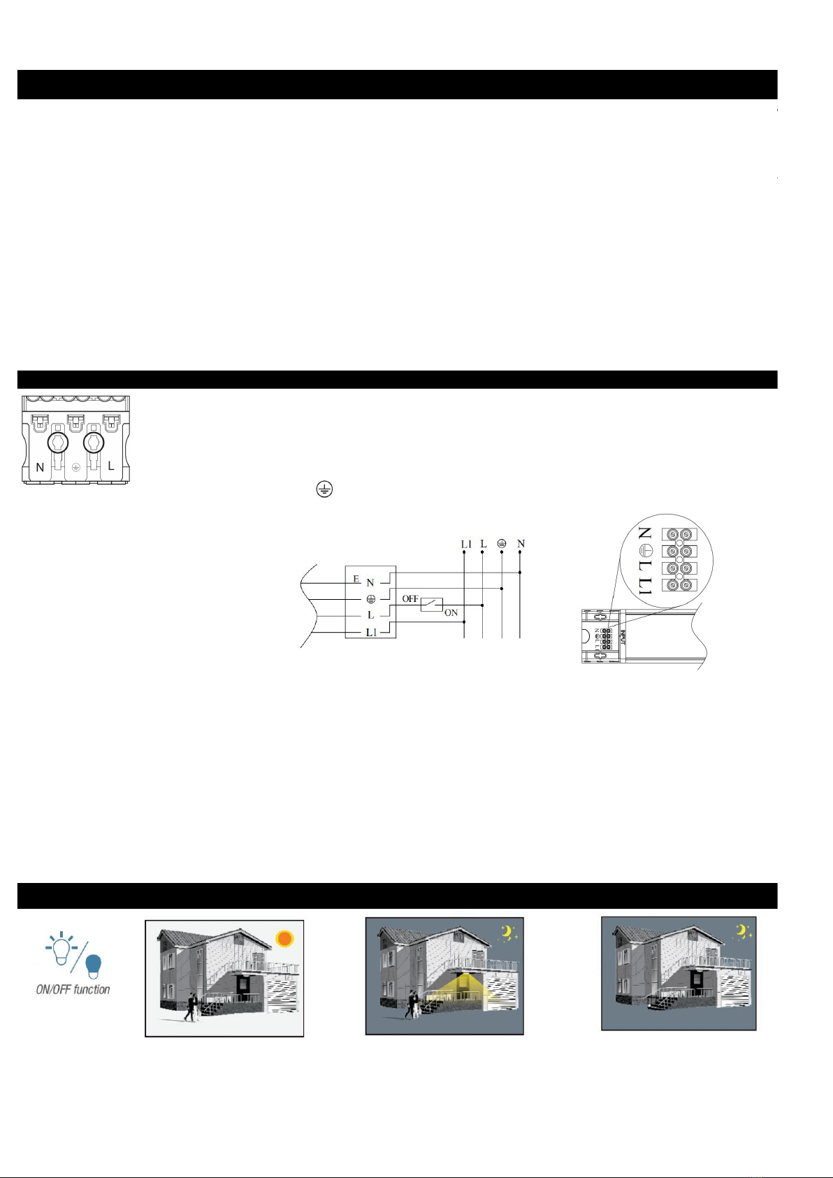
Wiring Connection
Wiring connection for all * Connect the incoming earth cable to the earth terminal
Non-Emergency units & ILBTF109 on connector block
LIVE - (Brown) to Terminal L * Connect the incoming neutral cable to the neutal terminal
NEUTRAL - (Blue) to Terminal marked N marked N on the connector block.
EARTH - (Green/Yellow) for Class 1 fittings to * Connect the incoming live cable to terminal marked L on
Terminal marked the connector block.
Wiring connection for emergency units
Connect the incoming earth cable to the earth terminal on the connector block
* Connect the incoming neutral cable to the neutral terminal marked N on the connector block
*PERMANENT LIVE - Black to Terminal Marked L1. This will endure that the battery charges.
Note: Any contiuned switching of the permanent live will reduce the battery`s considerably
*SWITCH LIVE - Brown to Terminal Marked L1
*There should be a loose flying lead connected to the battery.
*This needs to be attached to the empty socket found on the emergency control unit
Following power up on an emergency equipped unit,the green LED indicator should illuminate to indicate proper battery charging. If
power to an emergency equipped unit is disrupted or isolated, the indicating green LED will switch off,triggering the emgerncy LED`s
to illuminate for a minimum of 3 hours. Please Allow 24 hours charge for optimum duration.
Motion Sensor operation for motion sensing units
1. With sufficient ambient 2. With insufficient ambient 3. After elapse of hold time,the
light, the light will not be light, the sensor switches Sensor switches off the light
switched on. on the light when motion When no motion is detected.
is detected.

The microwave sensor version provides an ON/OFF function.It has maximum installed height of 3metres and maximum detection
area radius of 3metres.It is set up manually using the 8 configuration switches that are sited on the top of the LED and gear tray.
Detection area, hold time, Daylight Sensor and Operating Mode can be precisely set as follows:(Default setting: 100%, 5s, +∞,0s)
Detection area
In this area,movement will be detected and able to trigger the sensor. 100% detection area is also known as the strong sensitvity.
Hold-time
The period of light keeping 100% brightness after moving objects leavethe detection area
Daylight Sensor
Definition of the ambient brightness; only when the ambient brightness is lower than the preset specific lux amount, the sensor
will work; when it`s preset as ``+∞``,the sensor works everything it detects motion regardless the ambient brightness.
Operating Mode
If the sensor does not detect any movement, the light will remain at 10% brightness until the selected time expires, however
if any movement is detected during this period, the light will return to 100% brightness again and restart the timer.
Warranty
This unit carries 3 years warranty from the date of purchase,providing that it has been installed correctly and not modified in anyway.
Should a fault occur please contact the original place of purchase. Warranty for emergency batteres is 2 years.
Important Notes
* Operating and luminaire must be within rated temperature avoiding extreme humidity
* Operation must be within rated input voltage.
* Keep away form strong electromagetic radiation sources and protect from lightning strike.
* Should the unit malfunction, return to distributor or reseller. No user serviceable parts inside. Do not disassemble or attempt to
repair the luminaire outside of the installation guidelines.
* Do not install or use the luminaire if the housing/diffuser is found to be broken.
* Do not apply direct pressure to the diffuser.
* The Luminaire must be installed by a qualified electrician.
* The Luminaire should be positioned away from heat,vibration and liquid. Avoid contatct with any corrosive chemicals.
* The Luminaire should be mounted in free air it is recommended not to exceed 30°C ambient.
* Never cover the luminaire with beat insulation materials.
* The luminaire should positioned at least 1 metre away from radios, failure to do so may affect radio reception.
* FOR EMERGENCY MODELS - After the emergency lamp has been fully charged for a period of time,the battery the unit should be
replaced when the rated emergency discharge time is not reached.
* For indoor or outdoor use.
A. Make a right position for screw hole B. Fix the thread locker to the ceiling

C. Open the end with input mask according picture 1 & picture 2,then open corresponding preset line hole according to the
input cord loaction, pictures 3, and fix the cord clip.
D. Follow the reverse operation of picture 1 and picture 2 E. Adjust the position of the fixture
of step C, assemble the end cover and fix lamp on ceiling.
Warranty/Techinical and contact
information are all available at
www.integral-led.com
Intergral LED is a division of Intergral Memory plc,
Unit 6 Iron Bridge Closed, Iron Bridge Business Park,
London, NW10 0UF, UK
Intergral EU BV, 2801 DG, NL
WASTE ELECTRICAL PRODUCTS SHOULD NOT BE DISPOSED OF WITH
HOUSEHOLD WASTE.PLEASE RECYCLE WHERE FACILITIES EXIST.CHECK
WITH YOUR LOCAL AUTHORRITY FOR RECYCLING ADVICE.
This manual suits for next models
13
Table of contents
Other Integral LED Outdoor Light manuals


Popular Outdoor Light manuals by other brands


Above All
Above All STANDARD LED BOLLARD instruction manual

Paradise Datacom
Paradise Datacom GL22315 installation instructions

MOOD
MOOD CHIC instruction manual

EINHELL
EINHELL RT-CL 12 Li Original operating instructions

Levoit
Levoit Kana manual

Urban Electric
Urban Electric MARKHAM Assembly and mounting instructions