Integral Technologies Dvx 1000 User manual

Information in this document is subject to change without notice.
© Copyright 2005, Integral Technologies. All rights reserved.
MasterControl and Integral Technologies are trademarks of Integral Technologies. Other trade-
marks and trade names may be used in this document to refer to either the entities claiming the
marks or names or their products. Integral Technologies disclaims any proprietary interest in
trademarks and trade names other than its own.
Integral Technologies makes no warranty of any kind with regard to this material, including, but not
limited to, the implied warranties of merchantability and fitness for a particular purpose. Integral
Technologies shall not be liable for errors contained herein or for incidental or consequential
damages in connection with the furnishing, performance, or use of this manual.
Integral Technologies
9855 Crosspoint Blvd., Suite 126
Indianapolis, Indiana 46256 U.S.A.
User ManualUser Manual
User ManualUser Manual
User Manual
MasMas
MasMas
Mastt
tt
terContrerContr
erContrerContr
erControl vol v
ol vol v
ol verer
erer
ersion 4.3sion 4.3
sion 4.3sion 4.3
sion 4.3
June 2005June 2005
June 2005June 2005
June 2005
#3000-40077 Rev. 2#LN10021 0605


(continued)
TABLE OF CONTENTS
Introduction......................................................................................... 1
About the DVX 1000 Series...................................................................................... 2
What This Manual Covers ........................................................................................ 3
Precautions............................................................................................................... 4
Installation........................................................................................... 5
Installing DVX 1000 .................................................................................................. 6
Running the MasterControl Application .................................................................... 8
Accessing the MasterControl Database ................................................................... 9
Changing the SQL Server Password...................................................................... 10
Getting Familiar with MasterControl ............................................... 11
Overview of the MasterControl Screen .................................................................. 12
The Function Buttons ............................................................................................. 13
The Status Bar........................................................................................................ 14
MasterControl Configuration........................................................... 15
About the Setup Page ............................................................................................ 16
Adjusting the Video Display.................................................................................... 17
Configuring Hardware............................................................................................. 18
Important Note About Day/Night (Autoswitching) Cameras ................................... 20
Naming Cameras.................................................................................................... 21
Configuring Disk Usage.......................................................................................... 22
Defining MasterControl Users ................................................................................ 23
Configuring Motion Detection ................................................................................. 29
Understanding Motion Detection ............................................................................ 30
Assigning Cameras to Alarms ................................................................................ 34
Video Outputs and Touring..................................................................................... 37
Configuring Multi-Camera Output........................................................................... 39
Configuring Onscreen Display on Video Outputs................................................... 40
Archiving ................................................................................................................. 42
Configuring PTZ Cameras...................................................................................... 48
RemoteView Server Settings.................................................................................. 50

MasterControl Operation ................................................................. 51
Viewing Live Video on the Monitor Page................................................................ 52
Selecting Recording Modes.................................................................................... 58
Setting a Recording Schedule ................................................................................ 59
Searching for Recorded Video ............................................................................... 70
Viewing Recorded Video ........................................................................................ 75
Exporting Captured Images and Video .................................................................. 77
Using Easy Evidence.............................................................................................. 78
Bookmarking Video ................................................................................................ 80
Viewing Disk Usage................................................................................................ 81
Viewing the Activity Log.......................................................................................... 82
RemoteView ...................................................................................... 83
Introduction to RemoteView ................................................................................... 84
Connecting the Client and Server........................................................................... 84
Installing the RemoteView Software....................................................................... 85
Configuring a Dial-up Connection........................................................................... 86
Running the RemoteView Software........................................................................ 89
Important Information About Passwords ................................................................ 90
Overview of the RemoteView Screen..................................................................... 91
The Servers Page................................................................................................... 92
The Monitor Page ................................................................................................... 94
The Search Page.................................................................................................. 100
The Setup Page.................................................................................................... 105
How RemoteView Admin Changes are Applied ................................................... 105
The Alarms Page .................................................................................................. 108
The Schedule Page .............................................................................................. 109
RemoteView Server Settings................................................................................ 110
Appendix A: Plug-ins and Utilities ................................................ 111
Introduction to DVX 1000 Plug-ins ....................................................................... 112
DVXMonitor Plug-in .............................................................................................. 113
MotionAlarm Plug-in ............................................................................................. 116
DVXNotify Plug-in ................................................................................................. 119
Introduction to DVX 1000 Utilities......................................................................... 125
The Setup Utility ................................................................................................... 126
Appendix B: Synchronizing DVX 1000 Clocks............................. 127
Appendix C: Technical Support and Certifications ..................... 129

IntrIntr
IntrIntr
Introductionoduction
oductionoduction
oduction
Thank you for purchasing a DVX 1000 digital event recorder, a high-tech
monitoring and recording solution to cover all your security needs.
This chapter introduces you to your DVX 1000 system and the structure of
this manual. Included in this chapter are the following:
•A description of the main parts of your DVX 1000 system
•An outline of the chapters of this manual
Again, thank you for choosing a DVX 1000 digital event recorder for your
high-tech security needs.

2
ABOUT THE DVX 1000 SERIES
The DVX 1000 digital event recorder is a high-tech monitoring and recording solu-
tion that covers all your security needs. The following products are the heart of
the DVX 1000 package:
•The DVX 1000 box captures and compresses video for digital display
from up to 32 cameras for safe storage and easy access.
•MasterControlTM is the user-friendly software that allows you to easily
monitor and record video from multiple cameras. The simple configura-
tion instructions in this manual can help you set up MasterControl for
unattended recording for extended periods.
•RemoteViewTM is an application that allows you to download and view
live and recorded video from DVX 1000 over a network or dial-up con-
nection. You can also connect to and even configure multiple DVX 1000
systems remotely.
•The DVXMonitor, MotionAlarm, and DVXNotify plug-ins are standalone
applications that expand the reach of DVX 1000 by recovering from a
system failure or communicating messages externally from the system.
•Integal Media Player allows you to play back XPV and EXE files exported
from the DVX 1000 system on a separate PC.

3
WHAT THIS MANUAL COVERS
This manual takes you through the following topics, complete with illustrations,
step-by-step instructions, and detailed descriptions:
•Installation—includes instructions for installing the DVX 1000 system
and running MasterControl for the first time.
•Getting Familiar with MasterControl—describes the basic setup of the
MasterControl screen. It also offers brief descriptions of each of the
MasterControl functions.
•MasterControl Configuration—helps you set up MasterControl for ev-
eryday use. For example, it includes information on setting up user per-
missions, naming cameras, and configuring hardware to your desired
performance level.
•MasterControl Operation—explains the primary functions of
MasterControl. From viewing and capturing video to learning the impor-
tant scheduling feature, this chapter shows you how to actually operate
MasterControl for your daily security needs.
•RemoteView—describes the RemoteView software, including details
about downloading live and recorded video from a remote client PC.
•Appendix A: Plug-ins and Utilities—describes the standalone applica-
tions available on a DVX 1000 system.
•Appendix B: Synchronizing DVX 1000 Clocks—describes a procedure
that allows you to synchronize the Windows time of multiple DVX 1000
systems to a master source on a network.
•Appendix C: Technical Support and Warranty Information
If you require further assistance with your DVX 1000 system than this manual
offers, please refer to the technical support information available in Appendix C.

4
LITHIUM BATTERY—DANGER
The battery should be replaced only by a service technician. The
battery is a non-operator-replaceable cell. There is danger of explo-
sion if the battery is incorrectly replaced. Replace only with the same
or equivalent type recommended by the manufacturer. Dispose of used
batteries according to the manufacturer’s instructions.
CautionCaution
CautionCaution
Caution
RISK OF ELECTRIC SHOCK—DO NOT OPEN
To reduce risk of electric shock, do not remove the cover or back of
the DVX 1000 system. There are no user-serviceable parts inside. Re-
fer servicing to qualified personnel only.
CautionCaution
CautionCaution
Caution
PRECAUTIONS

InsIns
InsIns
Instt
tt
tallationallation
allationallation
allation
The installation of your DVX 1000 system consists of connecting the box to
its peripheral equipment (monitor, mouse, and so on). This chapter contains
specific instructions for the following:
•Installing DVX 1000
•Running the MasterControl application for the first time
•Accessing the MasterControl database and changing the SQL
password
Please pay special attention to the cautions and tips throughout the chapter.

6
INSTALLING DVX 1000
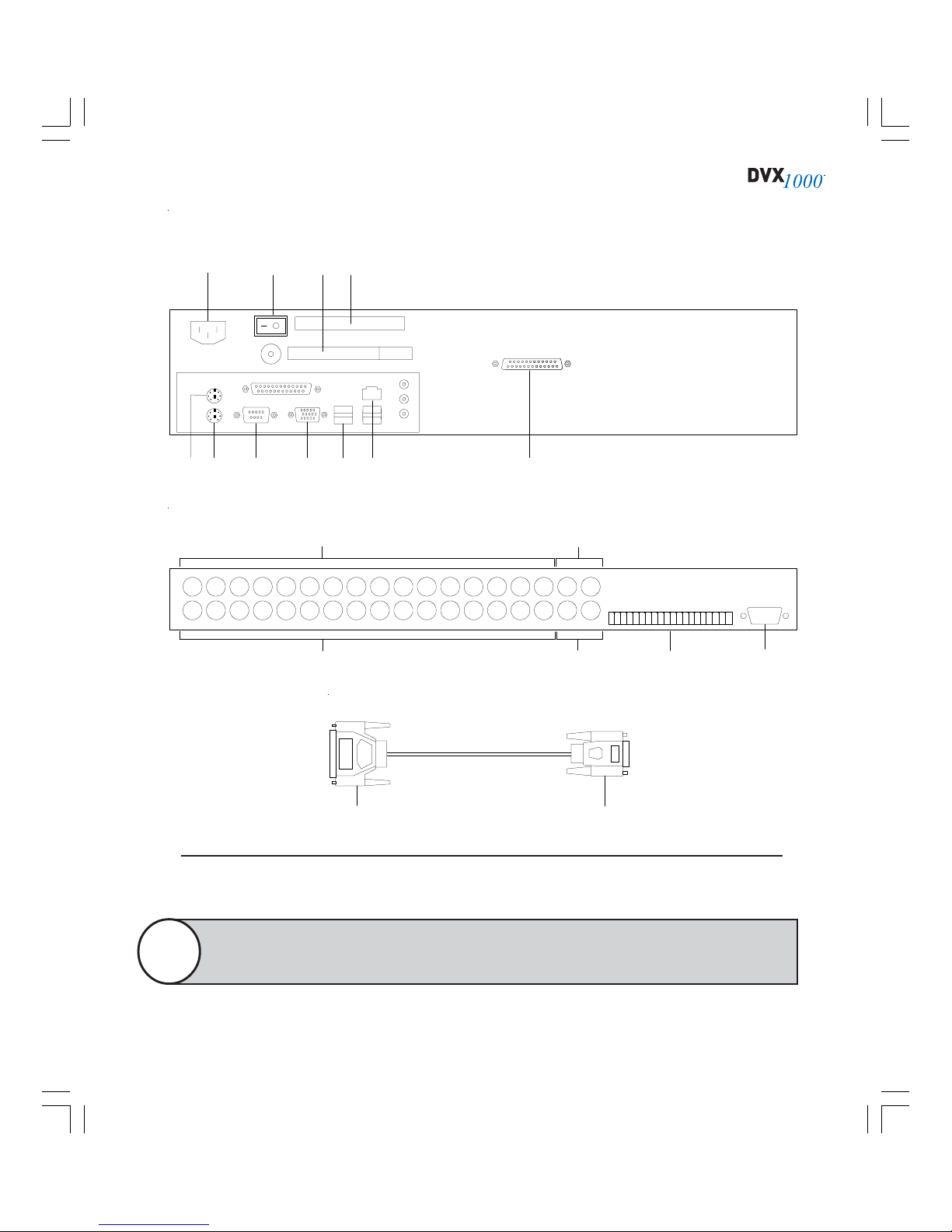
Use Figure 1 to complete the following installation instructions.
1. Plug the power cord into the power connector (A).
2. Plug the mouse into the mouse connector (B).
3. Plug the keyboard into the keyboard connector (C).
4. Plug the monitor into the monitor connector (D) and electrical outlet.
5. To provide a network or dial-up connection, connect a network cable to
the network connector (E) or a phone line to the modem (G).
6. (Optional) Connect your PTZ cameras to the RS-422 port (F) as described
in the PTZ installation manual.
7. (Optional) Wire the alarms to the green trigger block (H). From top to
bottom are inputs 1–16, two outputs, and two grounds. On the
MasterControl Alarms tab, the inputs are named Board Alarm 1, Board
Alarm 2, and so on. Connect only to voltages below 42V DC; external
devices connected to the DVX 1000 system should be in a SELV, non-
energy hazardous circuit.
8. Connect your cameras to the rows of BNC connectors (J).
9. (Optional) Connect the video output (K) to an TV or VCR.
10. For international use, set the input voltage switch (L) to 230V.
11. Plug the power cord into an electrical outlet.
12. To provide power to the DVX 1000 box, use the power switch on the rear
panel (M).
13. To turn on the DVX 1000 system, use the power switches on the front
panel of the box and on the monitor.
Only a 16- and 4-input system are shown on the facing page. A 9-input
system appears identical to a 16-input system, except that it contains
fewer camera input connectors.
Note

7
Figure 1
The rear panel of a DVX 1000 16-input system and a 4-input system. A 9-input system appears
identical to a 16-input system, except that it contains fewer camera input connectors (J).
MA BC E GDH
J
F
K
L
REAR PANEL OF DVX 1000 16-INPUT SYSTEM
INPUT 1 INPUT 2 INPUT 3 INPUT 4 INPUT 5 INPUT 6
INPUT 7 INPUT 8 INPUT 9 INPUT 10 INPUT 11 INPUT 12
INPUT 13 INPUT 14 INPUT 15 INPUT 16 OUTPUT
INPUT 1
INPUT 2
INPUT 3
INPUT 4
OUTPUT
MA BC E GDH
J
FK
L
REAR PANEL OF DVX 1000 4-INPUT SYSTEM

8
INSTALLING DVX 1000 XM
Use Figure 2 to complete the following installation instructions.
1. Plug the mouse into the mouse connector (A).
2. Plug the keyboard into the keyboard connector (B).
3. Plug the monitor into the monitor connector (C) and electrical outlet.
4. To provide a network or dial-up connection, connect a network cable to
the network connector (D).
5. Connect the 25-pin end of the XMUX2 cable (Q) to the DB-25 connector
on the back of DVX 1000 (E).
6. Connect your PTZ cameras to the RS-422 or RS-232 section of the PTZ
connector block (F). Alternatively, connect your PTZ camera to the serial
port (G) using an external converter.
7. Connect your cameras to the video input connectors on XMUX2-32 (L).
8. Connect Aux1–Aux4 (M) to television monitors, VCRs, or other analog
devices, if desired. Aux1 is a multi-camera output.
9. Connect the 26-pin connector of the XMUX2 Cable (R) to I/O Port on
XMUX2-32 (P).
10. (Optional) Wire the alarms to the trigger block on DVX 1000 (H) and on
XMUX2-32 (N). Connect only to voltages below 42V DC; external de-
vices connected to the DVX 1000 system should be in a SELV, non-en-
ergy hazardous circuit.
11. Plug the power cord into an electrical outlet.
12. Plug the power cord into the power connector (J).
13. To turn on the DVXe system, use the power switch on the rear panel (K).
(XMUX2 is powered by the DVXe system; there is no power switch or
power cord for XMUX2.)
14. Connect external USB modem to USB port (S).
9
A
REAR PANEL OF DVX 1000 XM SYSTEM
B
J
G C D
K
E
F H
S
L
REAR PANEL OF XMUX2-32
In
19753 1113151719212325272931
In
2 4 6 8 101214161820222426283032
L
M
N P
Aux2
Aux3
Alarm Inputs N
CC
N
O
G
N
D
Outputs
Aux4
Aux1
1 2 3 4 5 6 7 8 9 10 11 12 13 14 15 16
M
I/O Port
XMUX2 CABLE
INTEGRAL
Q R
Figure 2
The rear panel of a DVXe XM system and XMUX2-32 unit, along with the XMUX2 cable.
The BNC located under the power supply switch is unused on DVXe XM systems. The
multi-camera analog output is located in the Aux1 position on XMUX2-32.
Note
10
Tip
Be sure to change your DVX 1000 user ID and password immediately.
See the “Defining MasterControl Users” section of the
“MasterControl Configuration” chapter for information on how to do
this. The default administrator password is “letmein” for both Win-
dows and MasterControl.
RUNNING THE MASTERCONTROL APPLICATION
When you turn on the DVX 1000 system for the first time, MasterControl auto-
matically runs (you can also manually run the application from Start, Programs,
and MasterControl). When you see the Enter Password window, enter “adminis-
trator” for User and “letmein” for Password. MasterControl then scans for con-
nected cameras and opens up to the Monitor page. Now you are ready to config-
ure MasterControl for daily use.
Your DVX 1000 system has some of the same capabilities as a regular
personal computer. However, it is recommended that you do not use
your DVX 1000 system for anything other than operating the
MasterControl software. Wandering to other parts of the system could
damage DVX 1000’s intended functionality—so do this only at your
own risk. See the “Security Features” section of the “MasterControl
Configuration” chapter for more information.
CautionCaution
CautionCaution
Caution

11
ACCESSING THE MASTERCONTROL DATABASE
Only Windows users with Administrator permissions can operate MasterControl
initially; all other users see an error when they try to start the application. How-
ever, Windows users without Administrator permissions can be added manually
to the list of valid MasterControl users. To grant a non-Administrator Windows
user access to the MasterControl database, complete the following steps while
logged on to Windows with Administrator permissions:
1. From the C:\Program Files\Integral\MasterControl directory, run
ManageMCDB.EXE.
2. Click Next twice to view the Administrator tab (see Figure 3).
3. Under Authorized Accounts, double-click the Windows users that should
have permission to run MasterControl. Users listed with green checks
are authorized to run MasterContol, whereas users listed with a red “X”
are not authorized. Close Manage MCDB when finished.
If you demote the default Windows account to a non-administrator status in Win-
dows, be sure to authorize it using Manage MCDB.
Figure 3
Manage MCDB
allows you to
access the
MasterControl
database.

12
CHANGING THE SQL SERVER PASSWORD
The default password for the “sa” account, which is used to access SQL Server, is
“letmein.” If you need to change the “sa” account password for any reason, com-
plete the following steps while logged on to Windows with Administrator permis-
sions:
1. From the C:\Program Files\Integral\MasterControl directory, run
ManageMCDB.EXE.
2. Click Next twice to view the Administrator tab (refer to Figure 3).
3. Enter the new password and confirm it. Close Manage MCDB when fin-
ished.

Getting FGetting F
Getting FGetting F
Getting Familiar withamiliar with
amiliar withamiliar with
amiliar with
MasMas
MasMas
Mastt
tt
terContrerContr
erContrerContr
erControlol
olol
ol
The MasterControl screen provides an easy way to navigate the program’s
many features. Included in this chapter is basic information about the fol-
lowing aspects of the user interface:
•The function buttons
•The operation area
•The status bar
Also in this chapter are brief descriptions of the areas of MasterControl that
the function buttons link to. Detailed information about these areas can be
found in the “MasterControl Configuration” and “MasterControl Operation”
chapters of this manual.

14
OVERVIEW OF THE MASTERCONTROL SCREEN
The MasterControl screen is divided into three sections (see Figure 4):
•At the top of the MasterControl screen is a row of function buttons that
allow you to switch to each function so that you can easily set up or
change configurations and schedules, perform video searches, or moni-
tor camera inputs.
•The middle section of the MasterControl screen is reserved for the op-
eration of the function selected from the top row of buttons. This section
can include view screens, camera buttons, list boxes, and more, depend-
ing on the function selected.
•At the bottom of the MasterControl screen is a status bar that displays
information about the current date and time, the current status of each
camera, disk usage, and whether MasterControl is currently recording.
Figure 4
The MasterControl
screen consists of
three primary
sections.

15
THE FUNCTION BUTTONS
The six buttons found at the top of the MasterControl screen are your links to the
following pages:
The Monitor page is the primary way to monitor connected
cameras. You can view live video from user-selectable
groups of cameras.
The Schedule page allows you to control how and when
video is recorded from each camera input. Cameras can eas-
ily be set individually or in groups.
The Search page allows you to search for and view recorded
video. Just enter a time period and whether you want to
search for all video or for events only.
The Setup page is the master page for configuring disk us-
age procedures, hardware, system users, motion masks,
archiving, PTZ, and more.
The Help button allows you to search for help or choose
from a menu of help topics.
The Exit button closes the MasterControl program.

16
THE STATUS BAR
The narrow status bar at the bottom of the MasterControl screen (see Figure 5)
contains the following information:
•The current date and time.
Figure 5
The status bar
contains useful
information about
the time of day,
recording mode,
and disk usage.
•The recording status of up to 32 camera inputs. The inputs are repre-
sented by boxes, with input 1 on the left and the highest-numbered input
on the right. If a motion or alarm event is detected on a camera input
while scheduled for motion or alarm recording, the camera input boxes
become a certain color that corresponds with the active recording mode,
calling attention to the event. (See the “Selecting Recording Modes”
section of the “MasterControl Operation” chapter for an explanation of
recording modes and their associated colors.)
•The amount of disk space that is full (see the “Viewing Disk Usage” sec-
tion of the “MasterControl Operation” chapter for more information).
•The status of MasterControl operation—either Live (not recording) or
REC (recording).
•An icon tray that allows easy access to the MCNotify log, RemoteView
Server, utilities, and any installed plug-ins (see Appendix A). Only users
with Administrator rights can access RemoteView Server, whereas users
with Administrator and Supervisor permissions can access MCNotify log.
The MCNotify log icon changes to a camera icon with a red background
when PTZ errors occur. This log contains a wide variety of information in
addition to PTZ error messages.
See Appendix B, “Synchronizing DVX 1000 Clocks,” for important
information about maintaining the current date and time on your DVX
1000 system.
Note
Table of contents


