Integrated control Temp Minder Color User manual
Temp Minder Color™
Installation Manual
TM
Changes Or Modifications Not Expressly Approved By The Party Responsible For Compliance
Could Void The User’s Authority To Operate The Equipment
INSTALLATION INSTRUCTIONS
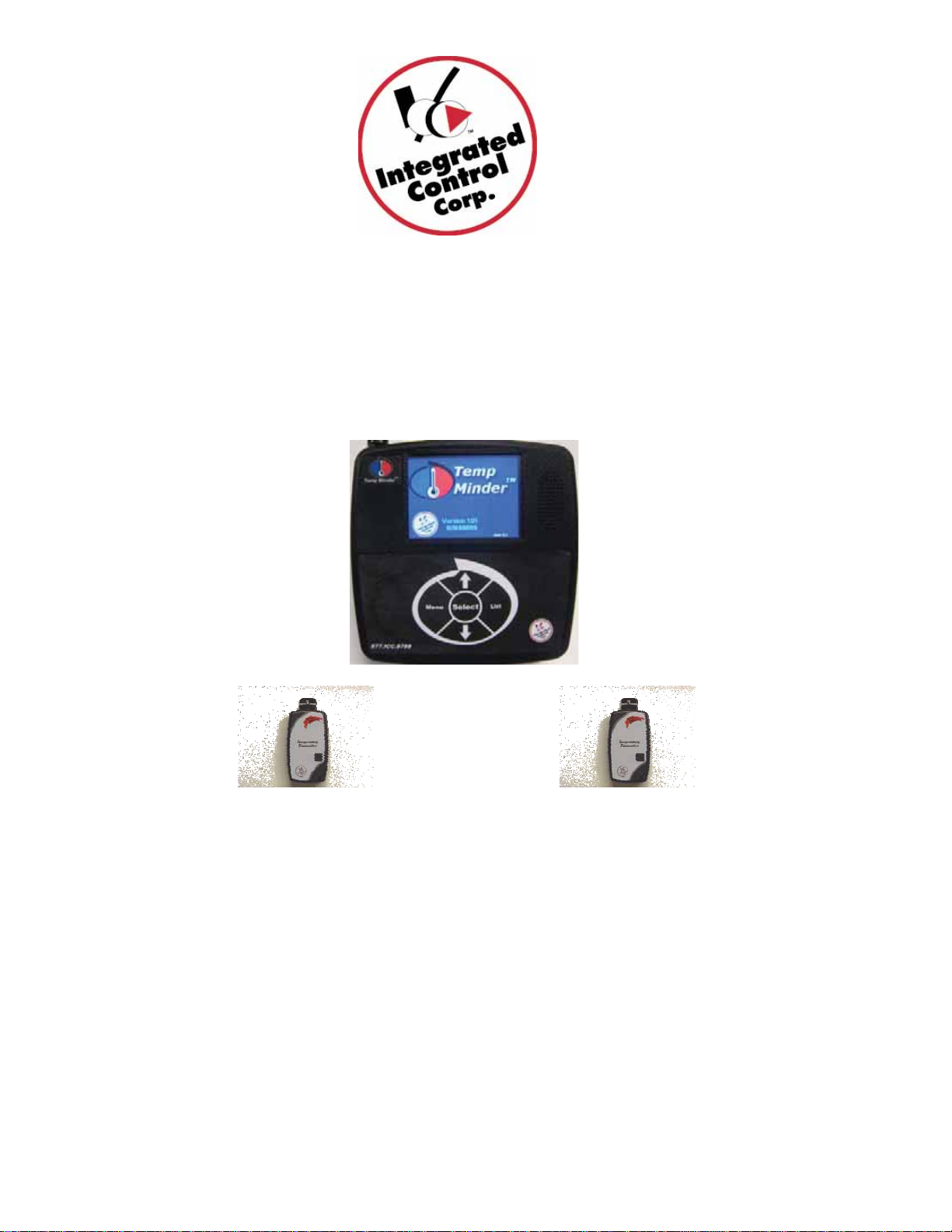
1 – What’s in the box?
Temp Minder™Installation Manual – 896950_I Rev A
Page 2
Temp Minder™
Display Control Box
The standard Temp Minder™ box consists of the following parts:
Temperature
Transmitter
Up to 24
Installation Kit
1 – 25’ Cat5 Cable
1 – 8’ Cat5 Cable
1 – AC-DC Power Supply
1 – Power Over Ethernet Adapter (POE)
Mounting Hardware
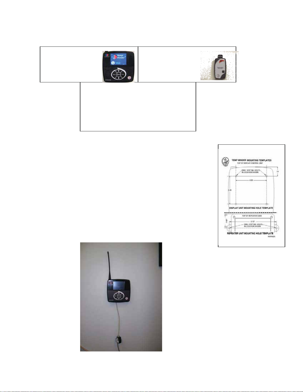
2 – Mounting the Temp Minder ColorTM Display Control box
TM
TM
The Temp Minder™display box should be mounted in a location that is
accessible by the staff and can also be heard if there is a temperature
alert. Included in the installation kit is a mounting template that can be
used for aid in drilling mounting holes.
1. Position the display control box and the drill template into the
desired location and tape the template into place.
2. Drill the two mounting holes as indicated on the drill template.
3. If required push the drywall anchors into the holes.
4. Tighten the supplied screws into the wall anchor leaving ½ inch
space between the wall and the screw head.
5. Mount the display unit and if necessary adjust the screws in or
out until the box is firmly mounted to the wall.
3 – Connecting the cables

1. Connect the cables using the wiring diagram below. After connecting the cables
use the provided cable clamps to secure the cables.
25’ Cat5 Cable
To Internet
Connection
Power
Supply
8’ Cat5 Cable
Power Over Ethernet
(POE)
Adapter
Back of Dis
p
la
y
unit
Note: If the order came with a repeater, DO NOT use the power supply labeled
“FOR USE WITH ICC REPEATER ONLY” with the POE Adapter
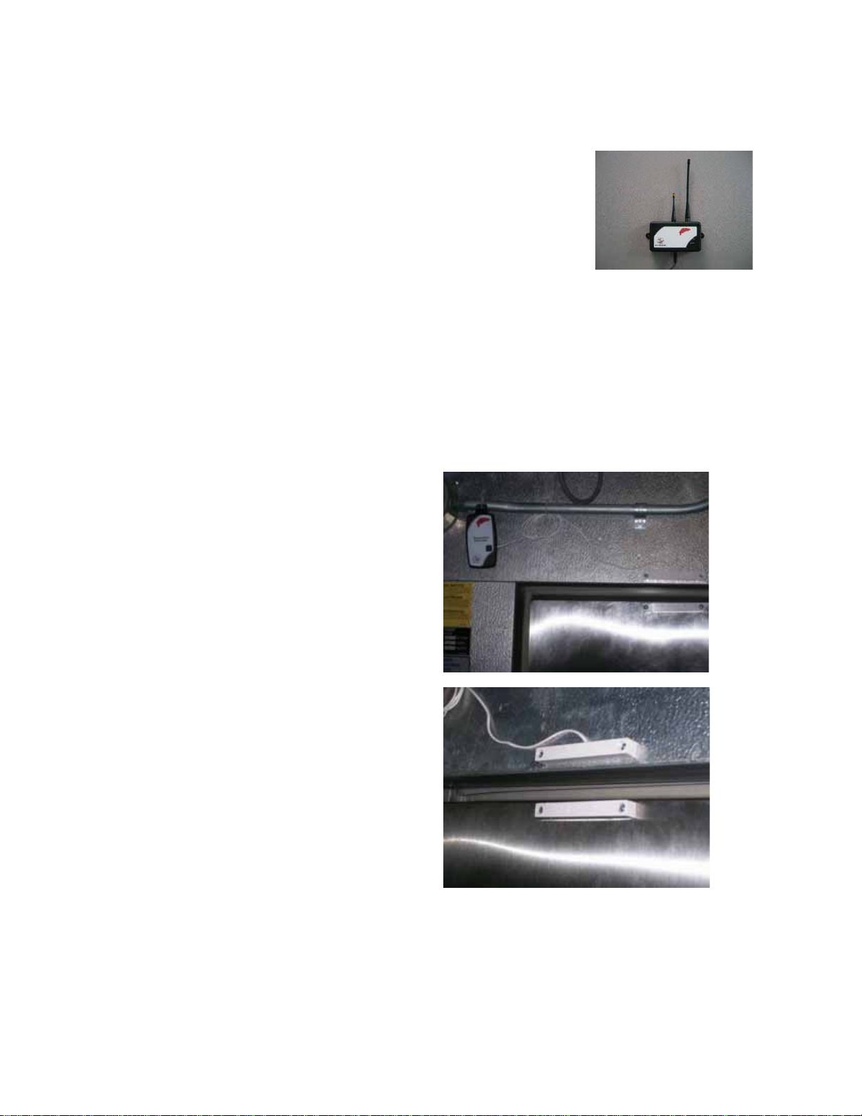
4 – Placing Temperature Transmitters
Repeaters may be required and can be purchased separately
Turn on Transmitter
1. Locate the Temp Minder™Set Up form that was shipped with the box.
2. Locate the device to be monitored that is the farthest distance from the Temp
Minder™Display Control Box.
3. Pull the tab located on the side of the Transmitter
4. Look at the display screen. On the list screen, find the transmitter that was
activated when the tab was pulled and verify that there is a temperature reading
for that transmitter.
Mounting Temperature Transmitter
Temp Minder™Installation Manual – 896950_I Rev A
Page 3

1. Mount the transmitter in the device to be monitored using the ICC provided zip
tie, velcro or screw. The optimal mounting is to zip tie the transmitter to the
existing shelving (as shown in the photo on the right) towards the side so the
transmitter cannot be obstructed by product.
Testing for signal strength
1. After mounting the probe, return to the display unit
2. Press the menu key and then press option 2 “Probe
Settings” on the display touch screen.
3. Press “Signal” on the touch screen
4. On the display to the right of the probe name and to the
left of the temperature, observe the time in seconds
counting up.
5. If the number resets to 1 every 10 to 30 seconds no
repeater is needed for that transmitter.
6. If the number consistently counts above 50, proceed to the installing repeater
section
Installing Repeater (sold separately)
1. Mount a repeater between the display control box and the transmitter, 5 to 10
feet from the transmitter.
2. Plug the power supply labeled “FOR USE WITH ICC REPEATER ONLY” into
the repeater and a power outlet.
3. After installing the repeater view the signal period and verify the
number is resetting to 1 every 10 to 30 seconds.
4. If the number consistently counts above 60, use another
repeater with different DIP switch settings (see below)
5. Mount another repeater with different DIP switch settings
between the first repeater and display control box 25 to 35 feet
away from the first repeater.
6. Repeat steps 2 - 3 mounting additional repeaters until the signal period is
constantly below 60.
Installing Long Range Repeater (Sold Separately)
When using multiple repeaters, change
the DIP switch settings as shown on
the right.
Repeater #3
Repeater #4
Repeater #2
O
N
DIP switch
Repeater #1
For the repeater furthest from the
TempMinder control (Repeater #1),
use the settings: 3 & 4 down/on.
The next repeater (#2) should have 3
down/on, 4 up/off
Continue in this sequence, no two
adjacent repeaters should have the
same settings.
Temp Minder™Installation Manual – 896950_I Rev A
Page 4
A long range repeater can be used for temperature transmitters that are more than 100’
away from the display control box. Rather than mounting several repeaters to transmit
the signal back to the display control, one set of long range repeaters may be mounted
(one within 20 feet of the temperature transmitter(s) and one within 20 feet of the
display control). If using a second long range repeater in the installation, there is no
need to mount a second long range repeater near the display
control.
1. Mount one long range repeater within 20 feet of the display
control unit. Mount the second long range repeater within 20
feet of the temperature transmitter(s).
2. Plug the power supply labeled “FOR USE WITH ICC
REPEATER ONLY” into the repeaters.
3. After installing the repeaters view the signal period and verify the number is
resetting to 1 every 10 to 30 seconds.
Repeat this page for additional Long Range Repeaters.
Installing Door Open Sensor (Sold Separately)
A door open sensor is used to monitor temperature as well as when the door is open in
the freezer/cooler.
1. Mount the transmitter in the device to be
monitored using the ICC provided zip
tie, velcro or screw. The optimal
mounting is to zip tie the transmitter to
the existing shelving (as shown in the
photo on the right) towards the side so
the transmitter cannot be obstructed by
product.
2. Mount the door open sensor that is
attached to the temperature transmitter
near the door. (Use the ICC provided
screws to mount.)
3. Mount the sensor that is stand alone
onto the door no more than 2.5” away
from the sensor that is attached to the
transmitter. (Use the ICC provided
screws to mount.)
Temp Minder™Installation Manual – 896950_I Rev A
Page 5

Temp Minder™ System
Warranty and Customer Support
Limited Factory Warranty
Integrated Control Corp. (ICC) warrants the products listed below that it manufactures and distributes (the “Products”) to be free from defects in
materials and workmanship, under normal use and service, for periods as stated starting on installation or first data transmission.
ICC warrants the following Product components to be free from defects in materials and
workmanship commencing with installation for the period(s) of time and on the conditions
listed below:
Factory Warranty
Temp Minder™ Control
Temp Minder™ Repeater
Temperature Transmitter
POE Adapter
Temperature Transmitter
w/ Door Open Sensor
Temperature Transmitter
w/ Humidity Sensor
Remote Probe
980950
980905
980902
980952
980902-20
980902-30
980902-10
18 Months
18 Months
18 Months - Excludes Batt
18 Months
18 Months - Excludes Batt
18 Months – Excludes Batt
18 Months – Excludes Batt
THE FOREGOING WARRANTIES ARE EXCLUSIVE AND IN LIEU OF ANY OTHER WARRANTY, EXPRESSED OR IMPLIED,
INCLUDING BUT NOT LIMITED TO ANY IMPLIED WARRANTY OF MERCHANTIBLILITY OR FITNESS FOR A PARTICULAR
PURPOSE OR PATENT OR OTHER INTELLECTUAL PROPERTY RIGHT INFRINGEMENT.
Without limiting the generality of the foregoing, SUCH WARRANTIES DO NOT COVER: Product misuse, tampering or
misapplication, improper installation or application of improper voltage, water damage, cleaning solution damage, overheating from
environment, battery life, condensation, data not programmed or acts of God.
Use of any Peripherals NOT supplied by ICC VOIDS the Warranty of the Electronic Units
Limitation of Remedies and Damages: ICC’s liability and Buyer’s exclusive remedy hereunder will be limited solely, at ICC’s option,
to repair or replacement of part under warranty, with respect to any claim made within the applicable warranty period referred to
above. Without limiting the foregoing, all Products shall be returned by Buyer, at its sole expense, to ICC for replacement or repair.
ICC reserves the right to accept or reject any such claim, in whole or in part. ICC will not accept the return of any Product without
prior written approval from ICC.
ICC WILL NOT BE LIABLE, UNDER ANY CIRCUMSTANCES, FOR CONSEQUENTIAL OR INCIDENTAL DAMAGES,
INCLUDING, BUT NOT LIMITED TO LABOR COSTS OR LOST PROFITS or PRODUCTS RESULTING FROM THE USE OR
INABILITY TO USE THE PRODUCTS OR FROM THE PRODUCTS BEING INCORPORATED IN OR BECOMING A COMPONENT
OF ANY OTHER PRODUCT OR GOODS OR FOR ILLNESS, INJURY OR LOSS OF LIFE.
Temp Minder™Installation Manual – 896950_I Rev A
Page 6
Other manuals for Temp Minder Color
1
Table of contents
Other Integrated control Measuring Instrument manuals


Popular Measuring Instrument manuals by other brands


TESTO
TESTO 416 instruction manual

Spectrum Technologies
Spectrum Technologies SPAD 502DL Plus Data Logger Manual

Molecular Devices
Molecular Devices SPECTRAmax PLUS 384 user guide

Leica
Leica Lino L2P5 manual

VOLTCRAFT
VOLTCRAFT AM-60X46 operating instructions

Keysight Technologies
Keysight Technologies B1500A user guide


