Intek Rheotherm 100CS User manual

WARRANTY
Intek, Inc. warrants each Rheotherm product to be free from defects
in material and workmanship under normal use and service, Intek's
obligation under this warranty being limited to making good any part
or parts thereof which shall, within one (1) year after delivery of such
product to the original purchaser, be returned to Intek with
transportation charges prepaid and which Intek's examination shall
disclose to its satisfaction to have been thus defective; this warranty
being expressly in lieu of all other warranties, express or implied and
all other obligation or liabilities on Intek's part. The purchaser will
assume all responsibility and expense for removal, decontamination
and reinstallation of equipment.
Rheotherm instruments are manufactured under United States patent numbers 4,255,968; 4,942,763, 4,949,578; 5,485,754; and 5,752,411;
Intek, Rheotherm, RheoVac, Rheovec, Rheomax and RheoSmart are registered trademarks of Intek, Inc.
Intek, Inc.
751 Intek Way
Westerville, Ohio 43082-9057
TEL: (614) 895-0301 • FAX: (614) 895-0319
website: www.intekflow.com
e-mail: [email protected]

©Intek, Inc. 2004
Manual No. A100CS9808CE Rev. A
I:\OFFICE\Web Site\distiller pdf\100CSCE.wpd
TABLE OF CONTENTS
SECTION 1 !GENERALINFORMATION ........................................ -1-
1.1 INTRODUCTION .................................................... -1-
1.2 DESCRIPTIONOFOPERATION ....................................... -2-
1.3 PRECAUTIONS ..................................................... -2-
SECTION 2 !INSTALLATION&STARTUP ...................................... -4-
2.1 TRANSDUCER...................................................... -4-
2.2 ELECTRICAL CONNECTIONS ........................................ -5-
2.3 STARTUP.......................................................... -6-
2.4 ADJUSTINGTHETRIPPOINT ........................................ -6-
2.5 USEASALEVELSWITCH ........................................... -6-
SECTION 3 !OPERATION..................................................... -7-
3.1 BEFORE YOU START ................................................ -7-
3.2 SWITCH SETTINGS ................................................. -7-
3.3 GENERALINFORMATION ........................................... -7-
3.4 USEASALEVELSWITCH ........................................... -7-
SECTION 4 !MAINTENANCE ................................................. -8-
4.1 GENERAL MAINTENANCE ........................................... -8-
4.2 SPAREPARTS ...................................................... -8-
4.3 TROUBLE SHOOTING ............................................... -9-
TABLE I. TROUBLE SHOOTING GUIDE ............................... -9-
SECTION 5 !CUSTOMERSERVICE .......................................... -10-
5.1 QUESTIONONEXISTINGHARDWARE ............................... -10-
5.2 TROUBLE SHOOTING .............................................. -10-
5.3 FACTORY AND FIELD SERVICE ..................................... -10-
5.4 DECONTAMINATIONOFEQUIPMENT ............................... -10-
5.5 QUESTIONSONNEWEQUIPMENT .................................. -10-
SECTION 6 !CUSTOMINFORMATION ....................................... -11-
6.1 UNITIDENTIFICATION ............................................. -11-
6.2 CONFIGURATION.................................................. -11-
6.3 SPECIALINSTRUCTIONS ........................................... -11-
Figure 1. Model 100CS Interconnect Diagram ...................................... -12-
Figure 2. Model 100CS PWB Layout Diagram ...................................... -12-

- 1 -
I:\OFFICE\Web Site\distiller pdf\100CSCE.wpd
SECTION 1 !GENERAL INFORMATION
1.1 INTRODUCTION
Rheotherm flow switches offer reliable flow switch protection in liquids, gases and slurries. They can
be used for flow/no flow detection, or specific low and/or high level alarms over a given 10 to 1 flow.
They are manufactured exclusively by Intek, Inc. and employ a patented thermal technique used by
industry since 1978. The unique transducer designs have protected sensors, are easy to install and
require little or no maintenance.
Each model 100CS flow switch consists of an explosion-proof electronics enclosure mounted on the
sensor head. The explosion-proof enclosure houses the round P/C board on which the relay and
electrical interface connector are mounted. Intek also has other switch models where the sensor and
electronics are separate units, for high temperature fluids or other conditions. In addition, a two relay
flow switch is available for indicating high and low flow conditions.
Key features of Rheotherm flow switches are:
• Non-intrusive flow monitoring — For pipe sizes from .030 to ¾ inch, flow sensing is done
from outside the flow tube.
• No moving parts — There are no rotating, translating, undulating or oscillating parts to wear,
stick, break or fatigue.
• Chemical compatibility — The wetted surface(s) can be any of a number of corrosion resistant
metals or alloys. There are no internal joints or seals in a TU type transducer. Where
necessary, the probe type transducers have no joints formed by dissimilar metals.
• Fluid pressure options to several thousand psi.
• Withstands over ranging — No damage or change in operation will occur due to excessive
flow rates many times higher than originally specified.
• Immunity to shock and vibration.
• Range of application includes flow monitoring in capillary tubes to large diameter pipes or
ducts.
The model 100CS is the simplest Rheotherm flow instrument, meant for low temperature applications.
Intek, Inc. also has flow switches (Model 100FS) for high temperature liquids and gases (up to 850°F)
and other extraordinary process conditions.
1.2 DESCRIPTION OF OPERATION

- 2 -
I:\OFFICE\Web Site\distiller pdf\100CSCE.wpd
The Rheotherm Model 100CS flow switch uses a thermal sensing technique. Two temperature sensors
are used — one is in thermal equilibrium with the fluid and provides a fluid temperature reference, while
the second temperature sensor is located near a heater so that its temperature is slightly above that of
the fluid. In a TU transducer, the temperature sensors and heater are attached to the outside of the flow
tube, whereas the probe type transducers have sensors and heater located in the probes which are
inserted into the stream. The amount of heat removed from the heated sensor by the stream is related
to fluid velocity. Hence, the measured temperature differential between the reference sensor and heated
sensor is a function of flow rate. Only Intek, Inc. is licensed to use this patented and trademarked
method for precision flow measurement.
Non-intrusive transducer Example of Example of
(TU) probe with probe with
NPT fitting flange fitting
1.3 PRECAUTIONS
1. Use proper input power — Check the label on the unit for the input power requirements.
2. Use reasonable care in handling the flow switch. Do not try to disassemble the transducer;
there are no removable parts.
TU — Excessive twisting or bending can damage the sensor. The flow tubes are thin-walled
tubing. Handle by the sensor body or electronics box to prevent tube damage.
Probes (NPT/2I, NPT/I, BF/2I, BF/I, etc.) — Take care not to bend the probes or damage the
tips. Do not try to remove or turn the electronics box.
3. Check the flow switch maximum temperature rating — Do not operate a transducer at or
subject it to a temperature above its specified limit.
4. Keep moisture out of the electronic enclosure. Once cable connections are made in the
electronic box, make sure the lid is tightly closed. Seal conduit lines if they can become wet
inside.
5. Keep transducer wetted surfaces clean and free of permanent layer build-up.
6. Do not exceed pressure limits specified on tag of the probe, tube or fittings.
98022-1

- 3 -
I:\OFFICE\Web Site\distiller pdf\100CSCE.wpd
7. Maintain a thermally stable environment (short-term) for the transducer and adjacent line.
(See SECTION 2 — INSTALLATION.)
These instructions cover installation, operation and maintenance of Rheotherm flow switches in standard
configurations. Any special information pertaining to your unit is covered under CUSTOM
INFORMATION (SECTION 6). Time should be taken to carefully read these instructions prior to
installation of the equipment. Should questions arise or problems occur, call Intek for immediate
assistance.

- 4 -
I:\OFFICE\Web Site\distiller pdf\100CSCE.wpd
SECTION 2 !INSTALLATION & STARTUP
The installation and startup of the Model 100CS flow switch must be performed by qualified service
personnel.
2.1 TRANSDUCER
!! IMPORTANT: All transducers have a directional arrow on the tag
and/or etched into a metal part. Before installing a sensor, please note
proper flow direction. This is critical to sensor operation.
The transducer style supplied with your meter is listed in the model code number in SECTION 6.
Proper installation of the sensor is necessary for achieving accuracy and repeatability. Installation
suggestions for each type of standard transducer are given here. For custom transducer installations,
refer to CUSTOM INFORMATION — SECTION 6.
Be sure wetted surfaces are clean before installing. If cleaning is needed, use non-residue solvent and
wipe dry. Keep moisture out of the electronics box. Make sure the lid is tightly sealed and, if supplied,
the gasket is in place. Seal conduit lines at the electronics box if conduit lines can become wet.
1. TU Transducers —
!! CAUTION: TU transducers are made with thin-walled tubing — use
care when installing.
!! CAUTION: The electronics box should never be rotated for any
reason.
Straight run for a flow switch is not a requirement, particularly for flow/no flow indications,
but for best repeatability some straight run is useful, such as 10 to 20 pipe diameters on the
inlet and 6 to 10 diameters on the outlet. If installed vertically, the flow should be going up
through the sensor. Connection in the line is via compression fittings, hose with clamp,
threaded fittings or flanges, whichever is appropriate. Care must be taken not to transmit a
twisting force through the transducer's midsection. The TU transducer, whether flanged or
not, must not be used to pull other piping together or to make up angular mismatch of fittings.
Fluid temperatures other than ambient require special attention. Thermal gradients from one
end of the transducer to the other, as well as along the radius of the connection pipe, are
undesirable. Therefore, effective insulation should be installed around the inlet and outlet
straight line runs. Gradients which may exist in the line further up stream can be removed if
an insulated elbow is installed in the line prior to entering the straight line portion of the
plumbing.
The ideal installation will provide the sensor with well established smooth flow, uniform
system temperature and consistent fluid media.

- 5 -
I:\OFFICE\Web Site\distiller pdf\100CSCE.wpd
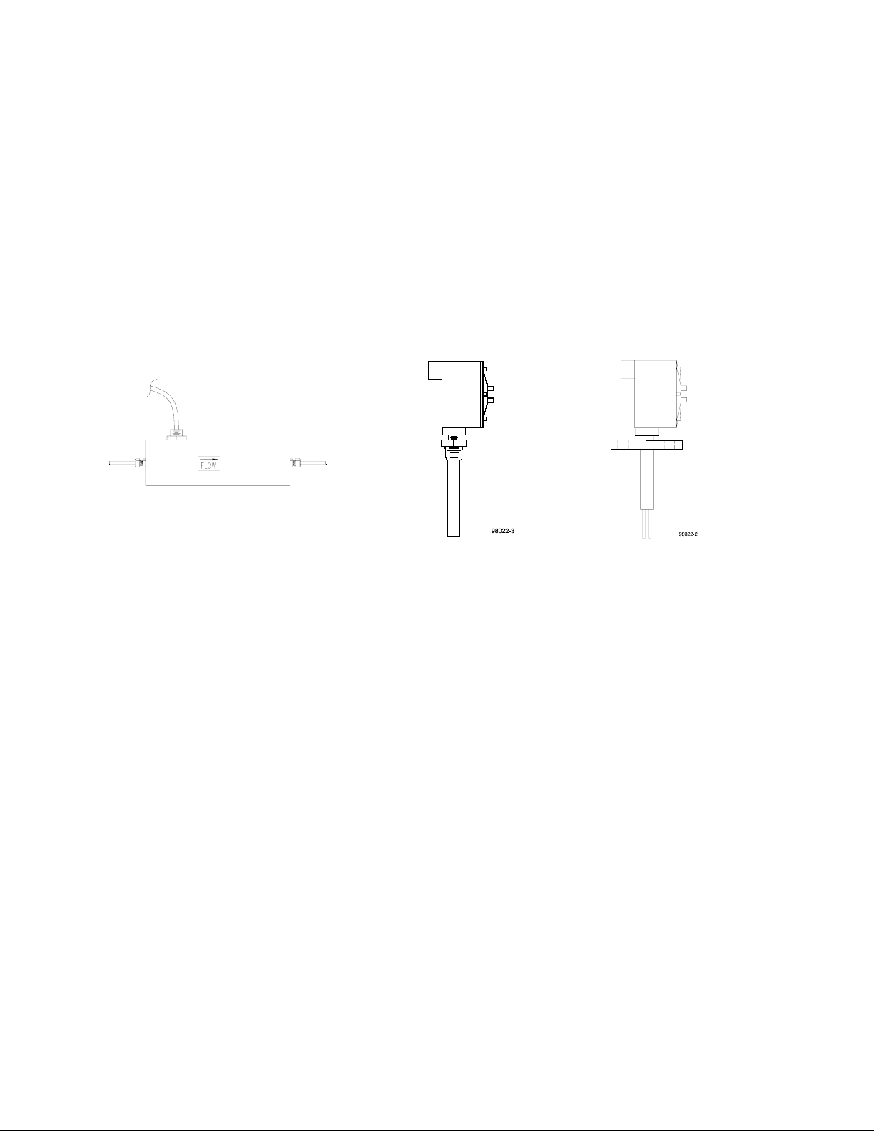
2. Insertion Probes —
Straight run is not critical, but if trying to hold a precise set point, some straight run is useful,
such as 10 to 20 pipe diameters on the inlet and at least 6 diameters on the outlet.
The various probe transducers are mounted through a threaded collar (NPT/2I) or flanged tee
(BF/2I). Other fittings and sensor designs are also available and are discussed on the Custom
Information page. Generally the probes are sized so the tips extend ½ to 1 inch beyond the pipe
center line when properly installed. However, for larger pipes, the probes may extend to within
1/8of a diameter from the inside pipe wall.
Proper alignment of the sensor with flow is important; the flow direction is indicated on the
transducer tag and/or etched into the transducer. All dual probe transducers are installed so that
the two probes are side-by-side across the fluid stream. Never rotate the electronics box. If this
occurs the flow switch could be damaged and/or installed misaligned with the flow direction.
For high temperature applications, the sensor and surrounding line should be well insulated. Leave
a portion of the transducer neck un-insulated to allow heat dissipation before reaching the junction
box.
2.2 ELECTRICAL CONNECTIONS (See Figure 1)
!! CAUTION: Prior to opening the electrical enclosure, service personnel
shall be properly grounded with an anti-static device to prevent damage to
components within the electrical enclosure.
The input power requirement is listed on the tag on the electronics enclosure; make sure the input power
source is compatible. The power requirement is 24 Vdc. The DC power supply must be well filtered and
grounded and comply with all applicable E.U. standards (i.e. EN61000-4 EMC).
The input power and relay connections are made as shown in Figure 1. Note the connector is removable for
easier insertion of the wires. Once all connections are made, firmly push the connector back onto its base.
Be sure the wires are stress relieved sufficiently to prevent an inadvertent disconnect.
!! IMPORTANT: In order to preserve the electromagnetic immunity levels
necessary for CE compliance the following must be strictly observed:
1. Power must be supplied via no smaller than 24 AWG (0.25 mm2) twisted, shielded copper wire.
2. Relay contacts must be connected to their load via a twisted, shielded cable of appropriate wire
gauge for the load. A minimum of 20 AWG copper wire (0.7 mm2) is recommended.
3. Both shields (power and relay wires) shall be terminated on the ground terminal of the flow switch
while leaving the opposite ends un-terminated.
4. Maximum rated load for the relay contacts is 5 amps resistive at no more than 30 Vdc.
5. Wiring shall be enclosed in a properly grounded, armored metallic sheath.
6. Additionally, for TU style instruments, earth ground the flow tube, using the tube ground
connection. Grounding is important for EMC immunity.

- 6 -
I:\OFFICE\Web Site\distiller pdf\100CSCE.wpd
Failure to follow these installation recommendations may compromise the electromagnetic immunity
characteristics of the flow switch, especially when installed in close proximity to high powered radio
transmitters or frequently switched heavy electrical loads, and may cause false indications from the flow
switch. The application of greater than 75 volts (AC or DC) to the relay contacts may create a personnel
safety risk.
The housing for a 100CS flow switch is a round explosion-proof enclosure. When ready for use, the housing
lid should be tightly screwed on. A gasket is included when rain tightness is required. Here again, the lid
should be on tight to make a good seal against the gasket.
2.3 START UP
Typically, Rheotherm flow switches come from the factory set up for a 10 to 1 flow rate range, and with the
trip level set approximately as requested by the customer. The trip level can be adjusted using the instructions
in SECTION 2.4.
When power is first turned on, the flow switch may indicate a high flow rate, even if there is no flow
occurring. Correct indication of flow level will result after an initial period, which can extend to about forty
(40) seconds and depends on where the trip adjust is set.
2.4 ADJUSTING THE TRIP POINT
Adjust the flow switch trip point as follows (see Figure 2, for trip potentiometer location):
All adjustments must be made by qualified personnel wearing an approved static discharge strap.
1. Establish a flow rate at the desired trip level. (This should be done with flow in the line, not at zero
flow. Select a flow rate below your normal usage. One example would be to use 50% of your
lowest normal flow rate as the set point.)
2. If the LED is green, adjust "Trip" potentiometer slowly clockwise just until the relay de-energizes
(LED turns red). This is the alarm condition.
3. If the LED is red, adjust "Trip" potentiometer slowly counterclockwise just until the relay
energizes (LED turns green).
4. If the relay cannot be made to drop out over the full range of the "Trip" potentiometer, see TABLE
I.
2.5 USE AS A LEVEL SWITCH (Insertion Probes Only)
The probe switch design can be used to provide one point level switch indication. When the probe tips are
submerged in liquid, the relay is energized and the LED is green. When the liquid level drops below the
probes and they are surrounded by air or vapor, the relay de-energizes and the LED turns red. If the sensor
is installed in a horizontal orientation (parallel to the ground), the two probe tips should be in the same
horizontal plane so that liquid coming from below touches them at the same time.

- 7 -
I:\OFFICE\Web Site\distiller pdf\100CSCE.wpd
SECTION 3 !OPERATION
3.1 BEFORE YOU START
The flow switch trip point adjustment requires qualified service personnel to access inside the enclosure (see
Sections 2.2). Make sure the trip point has been properly adjusted prior to start of operation.
3.2 SWITCH SETTINGS
Typically Rheotherm flow switches come from the factory set up for a 10 to 1 flow rate range, and with the
trip level set approximately as requested by the customer.
When power is first turned on, the flow switch may indicate a high flow rate, even if there is no flow
occurring. Correct indication of flow level will result after an initial period, which can extend to about forty
(40) seconds and depends on where the trip adjust is set.
For standard flow switches, the relay operates as stated below. For nonstandard units, the operation is
described in SPECIAL INSTRUCTIONS (SECTION 6).
Low Flow Switch — The relay is energized (N.O. contact is closed) and the LED is green when the
flow rate is above the trip level. Therefore, the alarm condition (relay de-energizes) occurs when the
flow rate drops below the trip level or there is a loss of power to the sensor (N.O. contact is open) and
LED color becomes red.
High Flow Switch — The relay operation is exactly as described above. When used as a high flow
switch, the alarm condition is considered to be when the relay is energized (N.O. contact is closed).
3.3 GENERAL INFORMATION
The Rheotherm instrument is compensatedfor a wide range of both ambient and flowing media temperatures.
However, abrupt changes in the temperature of the flowing material can cause the instrument to read the flow
rate improperly, which could lead to an inappropriate tripping of the relay or a delay in reading loss of flow.
A proper reading is obtained only when the transducer is in thermal equilibrium with the material. Typically,
a 20°F abrupt change in temperature may require 40 seconds to stabilize.
In general, the heater used in the transducer does not develop enough power to cause damage to the system
in the absence of flow. This includes those used in liquids even if the line becomes empty and filled with air.
Special cases will be discussed in the section entitled SPECIAL INSTRUCTIONS (SECTION 6).
3.4 USE AS A LEVEL SWITCH (Insertion Probes only)
The probe switch design can be used to provide one point level switch indication. When the probe tips
are submerged in liquid, the relay is energized and the LED is green. When the liquid level drops below
the probes and they are surrounded by air or vapor, the relay de-energizes and the LED turns red.

- 8 -
I:\OFFICE\Web Site\distiller pdf\100CSCE.wpd
SECTION 4 !MAINTENANCE
The maintenance of the Model 100CS flow switch must be performed by qualified service personnel.
4.1 GENERAL MAINTENANCE
!! CAUTION: Prior to opening the electrical enclosure, service personnel shall be
properly grounded with an anti-static device to prevent damage to components
within the electrical enclosure.
Certain precautions should be taken to insure proper performance of all models of flow instruments.
Since the measurement technique involves a signal resulting from heat transfer to the flowing medium,
care should be exercised to prevent build-up of varying layers on the walls of the transducer. Layers
such as bacterial growth, dried paints, gas bubbles and non-solubles can result in measurement below
actual flow rates. Periodic checks and cleaning should be performed to insure a clean pipe or probe
surface.
It should be part of normal maintenance procedure to check the system for proper functioning.
Experience and other observable conditions should be utilized to determine the frequency of inspection.
To test the flow switch action, the flow rate should be reduced below (for low flow switch) or raised
above (for high flow switch) the switching level. Then check and insure relay action and continuity of
the shut down or warning circuits which it operates.
The joints of all intrusive probe tips should be inspected for wear and corrosion.
4.2 SPARE PARTS
The Model 100CS has no user serviceable parts, except for one replaceable fuse (Wickmann plug-in
fuse, part no. 3720250041). If spare parts are required, a complete unit should be ordered and stocked.

- 9 -
I:\OFFICE\Web Site\distiller pdf\100CSCE.wpd
4.3 TROUBLE SHOOTING
!! CAUTION: The electronics are not protected against condensed
liquid water inside the enclosure. If conduit is used, be sure conduit is dry
or sealed at the instrument to prevent conduit condensation from entering
the enclosure.
TABLE I. TROUBLE SHOOTING GUIDE
OBSERVATION PROBABLE CAUSE REMEDY
Flow trip level continually
drifting downward with constant
flow.
1. Coating forming on
wetted surface of
transducer.
1. Clean transducer
periodically.
2. Adjust trip potentiometer
clockwise until layer
build-up stabilizes.
After switch has been operating
properly: relay trips with flow
above trip level and cannot be
adjusted using SECTION 2.4
instructions. Relay does not trip
when flow falls below trip level
and cannot be adjusted using
SECTION 2.4 instructions.
1. Bad electronic
component.
1. Contact factory.
Relay cannot be made to trip by
adjusting "Trip" potentiometer.
1. Initial flow rate estimate
was too low or too high.
2. Flow media change.
1. Check flow conditions.
2. Contact factory.
LED is not lit and relay stays in
alarm condition (N.C. contact is
made).
1. No power to electronics.
2. Blown fuse.
1. Check incoming power.
2. Replace fuse with ¼
Amp fast acting fuse
(fuse is in PWB socket).
3. Contact factory.

- 10 -
I:\OFFICE\Web Site\distiller pdf\100CSCE.wpd
SECTION 5 !CUSTOMER SERVICE
Intek's corporate philosophy is to solve our customer's difficult flow measurement/monitoring problems.
This means that each instrument is custom configured and calibrated for the application. When you
purchase a Rheotherm instrument you also receive Intek's outstanding customer service. For sales or
product service, call your local representative or Intek directly at (614) 895-0301 8AM to 5PM EST/EDT
weekdays or fax us anytime at (614) 895-0319. Our customer service staff will provide assistance
promptly. Our website at www.intekflow.com is available for additional information; for submitting
5.1 QUESTION ON EXISTING HARDWARE
To allow us to help you more quickly, please have the serial number of the equipment available before
you call. If your company is not the original purchaser the identity of the original recipient will also be
helpful.
5.2 TROUBLE SHOOTING
If you have reviewed SECTION 4.3 TROUBLE SHOOTING and have questions, please call our
experienced engineers for assistance. In many cases we can solve a problem over the phone. Please
provide as complete a description as possible of the problems encountered.
5.3 FACTORY AND FIELD SERVICE
Model 100CS flow switches cannot be serviced in the field. If a problem cannot be solved through a
telephone conversation with one of our engineers, the unit should be returned to the factory for
inspection.
To request factory service, a Return Material Authorization (RMA) and purchase order is required. Our
customer service staff will assist you with the required information to return instruments for service.
5.4 DECONTAMINATION OF EQUIPMENT
For the safety of your personnel and ours, any hardware that has been in contact with potentially
hazardous liquids or gases must be properly decontaminated before shipment to Intek.
5.5 QUESTIONS ON NEW EQUIPMENT
For a new Rheotherm application or any liquid or gas flow measurement need, visit us at our website,
www.intekflow.com or contact your local Rheotherm representative or the Intek technical sales
department at the above phone/fax numbers. Our staff will be pleased to answer all questions and
provide quotations.

- 11 -
I:\OFFICE\Web Site\distiller pdf\100CSCE.wpd
SECTION 6 !CUSTOM INFORMATION
6.1 UNIT IDENTIFICATION
Model no.:
Serial no.:
Customer identification:
6.2 CONFIGURATION
The configuration of this unit, as originally shipped from the factory:
Input Power: 24 Vdc
Line Connection:
6.3 SPECIAL INSTRUCTIONS
Reference Reference
GNone GInstallation
GTrip level adjustment required GOther
for start up

- 12 -
I:\OFFICE\Web Site\distiller pdf\100CSCE.wpd
Removable interface
connector
Enclosure lid
24-14 Ga
Flow switch electronics
Check enclosure label
for proper input power.
For VDC input, connect
positive to 'H' or '+' terminal
and negative to 'N' or '-'.
Figure 1. Model 100CS Interconnect Diagram
Figure 2. Model 100CS PWB Layout Diagram
Other manuals for Rheotherm 100CS
1
Table of contents
Other Intek Measuring Instrument manuals