0,191
0,194
0,197
0,200
0,203
0,206
0,209
0,212
0 25 50 75 100 125 150 175 200
EA-74
INSTALLATION AND MAINTENANCE
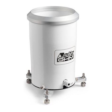
Upon request the rain gauge can be supplied ready calibrated at 0.2mm of rain
per commutation of the bucke (upon request, 0.1 or 0.5 mm calibration can be
provided ): the calibration value is shown on the instrument’s label.
The instrument must be installed in an open area, away from buildings, trees,
etc…, ensuring the space over it is free from all objects which could obstruct
rain measurements, and in an easily accessible position for the filter to be
cleaned periodically.
Avoid installation in areas exposed to gusts of wind, turbulence (for example the
top of a hill) as these may distort the measurements.
The rain gauge can be installed on the ground or raised 0.5 m, 1m or 2m above
the ground.
Three adjustable support feet have been provided for ground installation so that
the instrument can be levelled correctly, and the holes aligned so that it can be
fixed to the floor.
For raised installations a collar has been provided which fastens around the
base of the instrument on which the support staff must be inserted. The staff
may end with either a flange so that it can be fixed to the floor, or a tip to be
driven into the ground. The various fastening systems can be seen in fig. 2.
For the tipping device to function correctly and so for the measurement to be
correct, it is important that the instrument is placed perfectly level. The base of
the rain gauge is fitted with a bubble level.
For installation, unscrew the three screws at the sides of the cylinder that
supports the water collector cone.
Note: a heating resistor is fitted around the cone vertex in the HD2013R version.
To disconnect the power leads, the terminal block’s protection cover must be
removed and the connector plugged into the heater’s leads coming from the
cone needs disconnecting (see fig. 3).
Electrical connection
For the version without heating use a 2-wire cable with 0.5 mm2minimum wires
section, for the version with heating use a 4-wire cable with 2.5 mm2minimum
wires section. Use a shielded cable over long distances. Slide the cable through
the cable gland and fasten it with the cable fastener located near the entry hole
at the base of the rain gauge. Unscrew the terminal block protection cover and
perform the connections as shown in figure 3. The rain gauge output, indica-
ted at point 1 in the figure, must be connected to the input of the HD2013-
DB rain gauge data logger (please see the details in the manual of the data
logger) or to a pulse counter or to a data logger.
The heated version requires power (12 Vdc or 24 Vdc depending on the version
supplied) for the resistors: perform the connection as indicated at fig. 1.
If the connections are set correctly, the LED placed near the terminals will be
lit up.
+Vdc
GND
LED
Connector with
cone heater
Fig. 3 – Electrical connections (version with heating option)
Maintenance
Verify filter cleanliness periodically; check that there is no debris, leaves or
anything else that might obstruct the passage of water.
Check that the tipping bucket contains no dirt, sand, … deposits, or any other
obstruction.
If necessary, the surface can be cleaned with mild non aggressive detergent.
Technical characteristics
HD2013R HD2013
Power 12Vdc or 24Vdc ±10% / 165W
(to be specified in the order) ---
Type of output contact NC contact (opens during commutation)
Resolution 0.1 - 0.2 or 0.5 mm/commutation
(on request at the time of placing the order)
Precision
See normalized curve in fig.4. The curve is normalized at
0.2mm /commutation@50mm/h. If HD2013-DB data logger
is employed, the measure can be automatically normalized
according to this curve.
Operating temperature
range -20°C ... +60°C +4°C … +60°C
Heater intervention
temperature +4°C ---
Protection degree IP64
Collector area 400 cm2
Minimum sections
of the wires of the
connection cable
0,5mm² for the version without heating (HD2013)
2,5mm² for the version with heating (HD20123R)
Rain gauge with bird dissuader.Rain gauge installed on the ground.
Resolution (mm/commutation)
Rain intensity
Fig. 4 Resolution according to the rain intensity
