Intek RheoVac User manual

TABLE OF CONTENTS
SECTION 1 — GENERAL INFORMATION ....................................... - 1 -
1.1 INTRODUCTION ................................................. - 1 -
1.2 PRINCIPLE OF OPERATION ....................................... - 2 -
1.3 TECHNICAL SPECIFICATIONS ..................................... - 2 -
1.4 PRECAUTIONS .................................................. - 2 -
SECTION 2 — INSTALLATION ................................................ - 4 -
2.1 INTRODUCTION ................................................. - 4 -
2.2 RheoVac MONITOR INSTALLATION/SITE SELECTION ................ - 4 -
2.2.1 Transducer Site Selection ..................................... - 4 -
2.2.2 Electronics Unit Site Selection ................................. - 4 -
2.3 MOUNTING HARDWARE INSTALLATION .......................... - 6 -
2.4 TRANSDUCER INSTALLATION .................................... - 6 -
2.5 ELECTRICAL CONNECTIONS ..................................... - 8 -
2.6 RheoVac MONITOR GROUNDING ................................. - 13 -
SECTION 3 — OPERATION .................................................. - 15 -
3.1 GENERAL INFORMATION ....................................... - 15 -
3.2 SYSTEM START-UP ............................................. - 15 -
3.3 OUTPUT SIGNALS .............................................. - 15 -
3.4 IBM-PC SOFTWARE ............................................. - 16 -
3.4.1 SOFTWARE INSTALLATION ............................... - 17 -
3.4.2 SOFTWARE OPERATION .................................. - 17 -
3.4.3 DATA PROCESSING ....................................... - 18 -
3.5 CUSTOM SOFTWARE ........................................... - 19 -
SECTION 4 — MAINTENANCE ............................................... - 21 -
4.1 GENERAL MAINTENANCE ....................................... - 21 -
4.2 CALIBRATION .................................................. - 21 -
4.3 SPARE PARTS .................................................. - 21 -
4.4 TROUBLE SHOOTING ........................................... - 21 -
SECTION 5 — CUSTOMER SERVICE ......................................... - 25 -
5.1 QUESTION ON EXISTING HARDWARE ............................ - 25 -
5.2 TROUBLE SHOOTING ........................................... - 25 -
5.3 FACTORY AND FIELD SERVICE .................................. - 25 -
5.4 QUESTIONS ON NEW EQUIPMENT ................................ - 25 -
SECTION 6 — CUSTOM INFORMATION ...................................... - 26 -
6.1 UNIT IDENTIFICATION .......................................... - 26 -
6.2 CONFIGURATION ............................................... - 26 -
6.3 SPECIAL INSTRUCTIONS ........................................ - 26 -
©Intek, Inc. 1999
Manual no. RVAC Rev. D
I:\OFFICE\WPMANUAL\RHEOVAC\RHEOVAC.RVD

WARRANTY
Intek, Inc. warrants each RheoVac product to be free from defects in
material and workmanship under normal use and service, Intek's
obligation under this warranty being limited to making good any part or
parts thereof which shall, within one (1) year after delivery of such
product to the original purchaser, be returned to Intek with transportation
charges prepaid and which Intek's examination shall disclose to its
satisfaction to have been thus defective; this warranty being expressly in
lieu of all other warranties, express or implied and all other obligation or
liabilities on Intek's part. The purchaser will assume all responsibility
and expense for removal, decontamination and reinstallation of
equipment.
Rheotherm instruments are manufactured under United States patent numbers
4,255,968, 4,942,763, 4,949,578, 5,485,754 and 5,752,411. Intek, Rheotherm,
Rheovec, Rheomax, RheoVac and RheoSmart are registered trademarks of Intek,
Inc.
Intek, Inc.
751 Intek Way
Westerville, Ohio 43082-9057
Phone (614) 895-0301 – Fax (614) 895-0319
web site – www.intekflow.com
e-mail – techsupport@intekflow.com

- 1 -
Figure 1 RheoVac Air In-Leak Monitor
SECTION 1 — GENERAL INFORMATION
1.1 INTRODUCTION
For the first time, all necessary properties of the fluid in the condenser exhauster line are directly
measured to provide an accurate determination of air in-leakage. These properties are measured to
provide the power industry with the most advantageous and complete product for condenser system
diagnostics:
— the RheoVac®Air In-Leak Monitor System*
*USPNs 5,485,754; 5,752,411
The RheoVac air in-leak monitor system consists of multiple sensors configured in a single probe head
and an electronic signal conditioner and digital signal processor (DSP) unit. The sensing probe is
installed in the vacuum line between the condenser and the exhauster. The RheoVac monitor is superior
to all other methods in that it makes no assumptions about the dynamic condenser and vacuum line
environment. The sensor head employs the patented Rheotherm®technologyto provide an accurate flow
measurement. Additionally, temperature, pressure and water vapor relative saturation measurements are
made using a high accuracy platinum resistance temperature detector (RTD), a strain gauge pressure
sensor and a specially configured and calibrated water vapor saturation sensor.

- 2 -
1.2 PRINCIPLE OF OPERATION
The principal features of the RheoVac monitor are shown in Figure 1. At the heart of the RheoVac
monitor is the Rheotherm flow transducer which uses the same patented thermal sensing technique
employed in all precision flow instruments manufactured by Intek. Two temperature sensor probes are
used — one sensor is in thermal equilibrium with the flow medium and provides a temperature and flow
signal reference, while the second sensor is located near a constant power probe heater so that its
temperature is always above that of the fluid. The temperature of the heated sensor will vary with the
stream velocity of the fluid. Hence, the measured temperature differential between the reference sensor
and heated sensor is a function of flow rate, which is approximately proportional to the logarithm of
mass flow rate (USPN 4,255,968).
The Rheotherm flow sensor is calibrated to measure the total mass flow of the water vapor/air mixture.
From the other three measurements, the RheoVac electronics converts the total mass flow signal from
the transducer into two components, air mass flow rate and water vapor mass flow rate. This unique
measurement method is disclosed in two separate patents (USPN 5,485,754 & 5,752,411).
The RheoVac monitor is fully calibrated in the factory under dynamic fluid conditions identical to those
within the power plant vacuum line. No field adjustments are required.
1.3 TECHNICAL SPECIFICATIONS
Primary Calibration Accuracy:
±1% of reading
Repeatability:
±0.5% of reading
Operating Temperature:
Electronics: !20 to 120°F
Transducer: 40 to 160°F
Never subject transducer to
temperatures above 210°F
Operating Pressure:
0 to 10 inches Hg absolute
Process Connection:
Hot tap assembly
(1½” thread-o-let must be welded to
pipe for hot tap installation)
Wetted Surface:
300 Series SS and engineering plastic
Local Display:
air in-leakage (SCFM)
Input Power:
115 Vac, 50/60 Hz (±15V)
230 Vac, 50/60 Hz (±15V)
Signal Output:
4/20 mA (for 10 parameters)
RS 232/422
Storage Temperature:
!20 to 120°F
Storage Pressure:
15 psig (maximum)
1.4 PRECAUTIONS
•Read the entire manual before installing and operating the RheoVac monitor.
•Carefully select the best location for installation of the transducer probe. Adequate straight
run and freedom from standing water in the line are vital to achieving optimal performance
from the RheoVac monitor (See Figure 2).
•Use reasonable care in handlingthe transducer — the sensing components aredelicate. Take
care not to bend the probes, damage the tips, or otherwise obstruct the sensing ports.

- 3 -
Figure 2 RheoVac Probe Insertion Recommendation
•Use proper input power — check the power select switch position on the electronics. Select
either 115 Vac or 230 Vac before applying power.
• Check the transducer maximum temperature and pressure ratings — never operate a
transducer at or subject it to temperatures or pressures beyond its specified limits.
..WARNING - Never allow live high temperature steam to flow either direction in
the exhauster line where the probe is located.
• Keep moisture out of the enclosures — once all service connections are made, make sure the
enclosurelids are tightly closed and all gaskets are in place. Seal conduit lines at the
instrument.
SECTION 2 — INSTALLATION

- 4 -
2.1 INTRODUCTION
These instructions cover installation of the RheoVac monitor in its standard configuration. Additional
information pertaining to your unit is covered in SECTION 6 — CUSTOM INFORMATION.
Carefully read these instructions prior to installing the equipment.
2.2 RheoVac MONITOR INSTALLATION/SITE SELECTION
2.2.1 Transducer Site Selection
#Select the installation site. The location should provide the transducer sensing area with
well-established smooth flow, uniform system temperatureand pressure, and consistent non-
liquid phase flow medium. Pipe sections ahead of probe, in which water can accumulate,
must be avoided. Refer to Figure 2 and select the most preferred location that fits your
vacuum line configuration. Do not install the probe beyond any “trap” sections as shown in
Figure 2, Configurations B and D. Special installation instructions unique to your unit,
where applicable, will be noted in SECTION 6.3 SPECIAL INSTRUCTIONS. Refer to
this section now to review any special instructions.
#Check installation clearance. The transducer probe is almost 3 feet long and the hot tap
assemblyis about 13” long, so allow 4 feet of clearance for probe installation. Be sure there
are no obstructions around the vacuum line that will interfere with transducer insertion.
Figure 3 shows the proper insertion angle. THIS ORIENTATION IS IMPORTANT FOR
PROPER OPERATION.
#OBSERVE the selected site. It should be convenient for removal and replacing probe at any
time for service without building scaffolding or waiting for plant shutdown.
#Check operating conditions. The temperature and pressure limits of the unit should be
checked to ensure compatibility with your application.
2.2.2 Electronics Unit Site Selection
#Select the installation site. The electronics unit should be located in a dry area. The
electronics are not protected against condensed liquid water inside the enclosure.
#Check for input voltage access. The electronics unit should be located in an areawith access
to a 115 Vac or 230 Vac single phase, 50-60 Hz input power source.
#Checkcable distances. The distances from the transducer to the electronics unit and from
the electronics unit to the control room, or to the receiving equipment serial communications
port or to the analog input device, should not exceed the distances shown in Figure 4.
#Check electronics enclosure mounting area requirements. The RheoVac electronics
enclosure is NEMA 4, measuring 12"×10"×5". A detailed drawing of the mounting interface
is shown in Figure 5 (pg. 7).
#Check for accessibility to setup and use a portable computer (PC) at the site for trouble-
shooting. There should be a place to set up the PC and to open the electronics enclosure.

- 5 -
Transducer Installation Detail

- 6 -
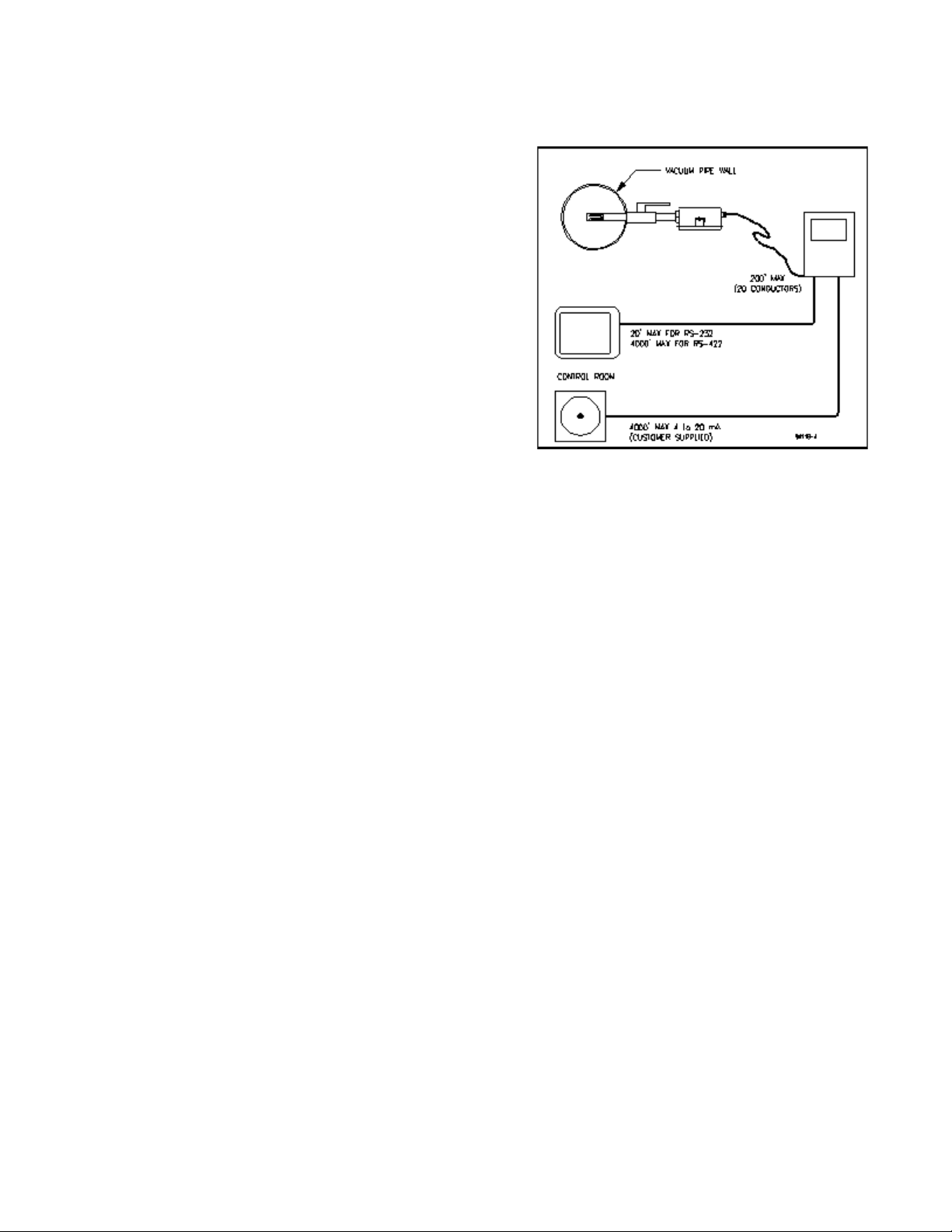
Figure 4 Maximum Cable Lengths
2.3 MOUNTING HA RDWARE INSTALLATION
ÎCheck hardware. Verify that the probe slides
through the hot tap assembly.
ÏCheck installation configuration. Make sure
the probe is parallel to the floor. (see Figure3).
ÐCheck installation clearance. Verifythere is a
probe insertion clearance of 4 feet from the
pipe wall.
ÑInstall the mounting hardware. Drill a 1½”
through hole and weld the thread-o-let onto
the condenser vacuum pipe (See Figure 3).
Thread the hot-tap assembly into the thread-
o-let. Use thread tape or pipe dope to seal the
connection.
ÒIt should be convenient to apply a force of
about 23 lb to remove or replace the probe
under plant operating conditions.
2.4 TRANSDUCER INSTALLATION
ÎCheck proper installation direction. The transducer has a directional arrow on the tag and/or
etched into a metal part. Before installing the unit, note proper flow direction. This is
important to instrument operation.
ÏCheck serial number. If more than one RheoVac unit has been purchased, make sure the
completeserial number of the transducer matches the complete serial numberof the separate
electronics unit. The transducer and electronics are a matched set. Mismatched components
will result in erroneous readings.
ÐVerify stop clamp location (see Figure 6). A stop clamp is attached to the probe as an
indication of its insertion depth. It is important this stay in place so the sensors are in the
correct location and ensure the probes do not contact the opposite pipe wall. The clamp’s
location was determined based on your pipe diameter, as shown in SECTION 6.2, and is
marked with a groove on the probe’s shaft. Refer to this mark if the stop clamp is
inadvertently moved.
ÑInspect the transducer probe tips. Be sure wetted surfaces are clean before installing.If
cleaning is needed, use a damp cloth wetted with alcohol and wipe dry using a soft, lint-free
cloth. Do not immerse probe in liquid alcohol or any other liquids.
ÒInstall the transducer.The instrument should be mounted through the pipewallusing thehot-
tap assembly. The transducer installs so that the two probes are side-by-side across the gas
stream. The transducer has a flow directional arrow on the transducer tag and/or marked into
the fitting. When installing under vacuum, do not allow the clamp to "slam" against the seal
nut upon opening the valve. Grasp the transducer shaft firmlybefore opening the ball valve.
Allow the transducer to slide through the valve by controlling the amount of grip on its shaft.
Special installation instructions, if any, will be noted in SECTION 6.

- 7 -
Figure 5 RheoVac Electronics Enclosure

- 8 -
Figure 6.
Transducer
Stop Clamp
Figure 7 Input Power Select Switch
2.5 ELECTRICAL CONNECTIONS
..WARNING: Read the entire contents of this section
before powering up the unit. Improper hookup may result in
damage to this instrument or the interfacing equipment.
ÎVerify/configure the input power. The input power
requirement is listed on the tag on the electronics enclosure.
Be sure the input power source to be used is properlyselected
in the unit. Input power can be either 115 Vac or 230 Vac
single phase, 50-60 Hz. The power configuration may be
changed in the field. Using Figure 7, locate the power select
switch on the lower printed wiring board and slide the power
select switch to either the 115V or the 230V position. Do not
apply power to the instrument until all other connections
and optional selections have been made.
.CAUTION: The Table 1 output signals, both !and +, are
isolated from the transducer and power ground. However,
the outputs are not isolated from each other; i.e. the 4-20 mA,
RS232/422, and status outputs are all common to each other.
All of the 4-20 mA receiver channels must have
independently isolated inputs.
ÏCheck the serial communication setup. If a distance of greater than twenty feet is needed for
the serial communications, RS-422 should be used instead of RS-232 (See Figure 4). Inspect
the header pin shunt (Figure 8) at JP14 (upper board) for the proper communication type.
Consult Intek if the jumper is not configured correctly.

- 9 -
Figure 8. Output Connections and Set-up
TABLE I. Ten 4-20 mA Wire Terminal Assignment
OUTPUT VARIABLE
DESCRIPTION
CONFIGURATION PIN ASSIGNMENT
Active 4-20 mA Passive 4-20 mA
!+!+
ACTUAL VOLUME FLOW [ACFM] ABBA
TOTAL MASS FLOW [lbs/hr] C D D C
WATER VAPOR MASS FLOW [lbs/hr] E F F E
RheoVac PRESSURE ["Hg] G H H G
WATER VAPOR SPECIFIC VOLUME [cu. ft/lb] I J J I
WATER to AIR MASS RATIO K L L K
RELATIVE SATURATION [%] M N N M
PARTIAL PRESSURE, WATER ["Hg] O P P O
AIR IN-LEAK [SCFM] QRRQ
RheoVac TEMPERATURE [°F] S T T S
NOT USED U U U U
ÐRheoVac units have ten 4-20 mA outputs. These outputs can be configured collectively for either
passive or active transmitter. The units are shipped from the factory with the output jumpers in
the active position; i.e. the transmitter provides the current source. Figure 8 shows the locations
of the 4-20 mA select jumper, JP13 of the lower board — active position is shown.
.CAUTION:changing the passive/active jumper changes the field wiring polarity and affects
all ten 4-20 mA channels. See Table I for wire terminal identifications.

- 10 -
Monitor Wiring Detail (with 10 channel 4-20 mA output)

- 11 -
Figure 10 - 4-20mA Output Circuit
ÑFigure 9 provides the RheoVac wiring
detail for the 10 channel 4-20 mA outputs.
Table I provides the appropriate
connection identification. As stated, the
output signals are not isolated from each
other and therefore the 4-20 mA receiver
channels must be independently isolated.
Atypical current output circuit is shown in
Figure 10. The current control circuitry
works by controlling the (!) side return
current through Q1 which returns current
through the isolated, but circuit-common,
ground (L1). When the 4-20mA output is
configured as active, the (+) terminal is
connected to a common 35 to 40Vdc
supply (Vunreg). The circuit “A” is
jumpered to the (+) output terminal and
“B” is jumpered to the (!) terminal. For
passive mode, the “A” is not connected,
the “B” is jumpered to the (+) terminal,
and the (!) terminal is connected to
isolated circuit ground (L1).
The remaining outputs - RS232/422 and status, are all (!) terminated to isolated circuit
ground. A single chassis or earth ground wire should be connected to the minus of any one
and onlyone of the receiving devices. This prevents high or noisy common-mode “floating”
potentials between the isolated transmitter and grounded transducer circuits. Do not connect
aground wire to each output. Again, the 4-20mA, RS232/422 and status outputs are all
common to each other and should be connected to isolated input cards.
ÒThe status output located on field wiring terminal, JP7, is adigital 0-15Vdc output. This output
willgo low in the event of afaultor power loss. Theremaining JP7 outputsarenot normallyused
with the RheoVac monitor and shouldbe left unconnected. If anon-standard option has been
ordered there will be additional notes in the SECTION 6.3 SPECIAL INSTRUCTIONS.
ÓMount the transmitter enclosure. Install conduit such that all seals are watertight and rigidly
secure. A separate external power switch is recommended to shut the equipment off during
outages. When the vacuum system is on-line, do not turn off power to the RheoVac monitor
unless you are preparing to take the probe out of the pipe.
ÔChoose a path for the transducer to transmitter cable conduit. Route the transducer interface
cable through the conduit (See Figure 9). The cable is labeled at both ends. DO NOT CUT
OR SPLICE THE CABLE, AS THIS WILL DESTROY THE LABELING AND MAY
AFFECTTHE INSTRUMENT CALIBRATION. Pull the cable through the conduit starting
at either end; coil up the remaining length outside the transmitter or transducer enclosure, or
in a cable junction box.

- 12 -
ÕPull wires through the conduit. Wire for power connection must be at least 24 gauge. After
pulling the wire, pot the conduit or wires near the enclosure if there is any possibility of
water from condensation or spray entering the enclosure through the conduit.
.CAUTION:The electronics are not protected against condensed liquid water inside the
enclosure. Be sure conduit interfaces are dry or sealed at the instrument to prevent
condensation that may be present in conduit lines from entering the enclosure.
ÖMake wiring connections. Power should be off at this time. Refer to Figure 9 for RheoVac
monitor wiring detail. Make power and transducer connections first on the lower circuit
board. Next connect the 4-20 mA signal wires at JP3 and the two status output wires at JP7.
There are no other terminals used on the upper board connector JP7.
..WARNING: Verify the wiring. The equipment can be permanently damaged if not wired as
instructed in this manual.
Wire Color Label Wire Color Label Wire Color Label
Drain Wire (Black) ARed HBlack/Brown Stripe O
Brown BYellow IGreen Stripe P
Orange CPurple JBlack Stripe Q
Blue DGray KRed Stripe R
White EBrown Stripe LYellow Stripe S
Green FOrange Stripe MPurple Stripe T
Black GBlue Stripe NGray Stripe U
×Install serial communication interface (see Figure 11, Pg. 14). Connections are made to the
serialcommunication receptacle with a cable with six-position RJ-11 plugs (phone type
jacks) supplied as an accessory. When using the RS-232 output, plug the RJ-11 connector
of the supplied cable into the RheoVac unit’s RS-232 receptacle. Plug the other end of the
RJ-11 cable into the provided RJ-11 to DB-9 adapter. The DB-9 adapter should then be
plugged into any standard IBM-PC compatible RS-232 port. Table II and Figure 11 provide
information on the connections.
Usually an RS-422 signal is converted to RS-232 before it is connected to a PC. The
converters do not have a standardized pin assignment, so use of the RS-422 output is less
straight-forward. The DB-9 pin out shown in Table II applies to an interface module,
QCOM-2, made by QSI Corporation. Other modules may have different wiring. Contact the
factory if you need assistance in using the RS-422 output.
Please note, the transmitter supports only one communications type at a time.
Close the lid of the enclosure. Make sure it is tight enough to make a good seal against the
gasket and ensure all other enclosure openings are completely watertight.

- 13 -
TABLE II. RJ-1 1 t o DB-9 Module Adapter
RS-232 CONFIGURATION RS-422 CONFIGURATION
RJ-11 Pin Out DB-9 Pin Out RJ-11 Pin Out DB-9 Pin Out
1Tx (transmit) 1N/C 1Tx+ (transmit+) 1Rx!(receive!)
2N/C 2Tx (transmit) 2Tx!(transmit!)2Rx+ (receive+)
3Rx (receive) 3Rx (receive) 3Rx+ (receive+) 3Tx+ (transmit+)
4N/C 4N/C 4Rx!(receive!)4N/C
5Power (+5V) 5Ground 5Power (+5V) 5Ground
6Ground 6Pulled high 6Ground 6Tx!(transmit!)
7N/C 7TBD
8Pulled high 8TBD
9N/C 9TBD
2.6 RheoVac SYSTEM GROUNDING
The RheoVac electrical system includes the RheoVac monitor and your data collecting inputs. In
general, it is good practice to use a single point grounding scheme to terminate the system output circuit
to a stablereference potential. Impropergrounding maycause significant datanoise, or in extremecases,
damage your equipment. To simplify this task, determine which outputs you will be using and refer to
the following section for specific grounding instructions.
• RS232/422 Serial Output Only - Many PCs have non-isolated serial ports. You must
determine if your serial port is isolated. With your PC (or DCS, etc.) powered and plugged
into a groundedoutlet measure both the Vdc and Vac between the local circuit’s earth ground
and pin 5 of the PC’s RS232 DB-9 connector. If the voltage is not zero the circuit needs to
be grounded. Connect a locally earth-grounded wire to the RheoVac instrument’s “OUT1”
(!) terminal of JP7 located next to the RS232/422 jack (see Figure 9). If the voltage reads
zero, no additional grounding should be attached. Additionally, we have seen noise
problems with certain laptop computers when they are connected to their external power
supplies. Some of them are not fully isolated and have signal noise levels as high as 12Vac
on the serial port GND pin. In this case, the circuit should also be grounded by connecting
a wire to the RheoVac’s “OUT1” (!) terminal.
•4-20mA Output Only - If only a single output channel is used, it may be connected directly
to a non-isolated input channel without any additional grounding. Any additional output
connections require isolated inputs. If all inputs are isolated, regardless of how many are
used, a single channel should be grounded locally near the input card(s). In this case, connect
a locally earth-grounded wire to one of the 4-20mA (!) terminals.
•Multiple Outputs - Review the special wiring configurations above. Connecting all of the
used outputs to isolated input devices results in one common isolated circuit. This common
circuit needs to be grounded at a single point. Choose one of the ground points listed above.

- 14 -
Serial Communications Interface

- 15 -
SECTION 3 — OPERATION
3.1 GENERAL INFORMATION
The RheoVac monitor is compensated and linearized for a wide range of flowing media temperatures,
pressures, and water vapor contents. However, abrupt changes in these parameters can cause the
instrument to temporarily read theflow rate improperly, which could lead to transient spikes in the flow
indication. In particular, if liquid (water) hits the probe tips, there will be high flow indications until all
the water vaporizes. This is a rare occurrence which should not happen if the transducer is properly
installed, according to instructions in SECTION 2 — INSTALLATION.
3.2 SYSTEM START-UP
The RheoVac monitor has been designed for fast warm up following turn-on of power. When power is
first turned on, no differential temperature will exist between the heated and reference probe sensors.
The transmitter is programmed to apply heat to the sensor for a set period of time or until a factory set
value is reached. Then the heater will return to normal. During this initialization period, the display will
have the message '*INTEK, INC.*' on the top line and '*(614)895-0301*', the phone number of Intek,
on the bottom. This message will then change to '*RheoVac*' and the unit's serial number. The bottom
display line will then change to 'initializing'. During this period the status output will be low (alarm
condition) and the analog outputs should be ignored. Further, no data is being transmitted over the serial
ports. The flow value will be monitored internally for stability, which will occur before the display is
set to the normal reading state. After the start-up sequence, program execution is sent to the main
instruction loop. It takes several seconds to execute the initialization sequence.
Upon a "cold" initial start-up of the RheoVac monitor, the transducer may take several minutes to give
accurate air in-leak flow measurements. During this time the probe is transitioning to thermal
equilibrium conditions under vacuum.
3.3 OUTPUT SIGNALS
Standard on all RheoVac instruments are one 2 x 20 alpha numeric LED backlit display, ten 4-20 mA
analog outputs,one 0-15V digital status port, and one serial communication port. Each process variable
is a linear, fully temperature and pressure compensated value onany of these readable outputs. All 4-20
mA output signals are scaled such that 4 mA represents 0% of the rated full scale value and 20 mA
represents 100% of the rated full scale value. The standard full scale values and definitions of all
process variables are listed in Table III.
Note: When the pressure rises above the calibrated range of 10" Hg absolute, all of the flowoutputs will
indicate zero. In some instruments the display will read "General Fault Mode 6" at higher pressures,
such as one atmosphere. This is not a problem and the unit will read correctlyunder vacuum conditions.
Therefore, no flow rates will be reported when the generator is off-line or during hogging until the
pressure falls below 10" Hg absolute. All other variables will continue to be output normally.

- 16 -
Table III. Process Variable Definitions and 4-20 mA Range
PROCESS VARIABLE
4-20 mA
FULL
SCALE
VALUE
PROCESS VARIABLE DEFINITION
ACTUAL VOLUME FLOW
[ACFM] 5000
The actual volumetric flow rate of gases leaving the condenser. It is a
measure of exhauster capacity. Decreased capacity means pump
degradation.
TOTAL MASS FLOW
[lbs/hr] 10000 The total mass flow rate of the flowing gas. Note: this value is not a
measure of air in-leak. It is a measure of steam jet ejector capacity.
WATER VAPOR MASS FLOW
[lbs/hr] 8000 The water vapor component of the flowing gas being removed from the
condenser.
RheoVac PRESSURE
[" Hg] 30 Absolute pressure at the RheoVac probe head. Should be equal to or less
than turbine back pressure.
WATER VAPOR SPECIFIC
VOLUME [cu. ft/lb] 10000 The inverse density of the water vapor present in the line.
WATER to AIR MASS RATIO 20 Ratio of water vapor flow rate to dry air flow rate. Defines “vacuum
quality.”
RELATIVE SATURATION
[%] 100 The percent concentration of water vapor in the extraction line relative to
saturation.
PARTIAL PRESSURE, WATER
["Hg] 10 The partial pressure of water vapor in the vacuum line.
AIR IN-LEAK
[SCFM] 100 Actual measure of air volume flow rate passing the RheoVac sensor head,
normalized to standard conditions (70°F, 29.9" HgA).
RheoVac TEMPERATURE
[°F] 210 Temperature of the flow media at the RheoVac probe head.
3.4 IBM-PC SOFTWARE
IBM-PC Windows 95 compatible software has been provided. This software performs four primary
functions. It allows the user to:
• access data stored inside the RheoVac monitor over the last 24 hours
• chart all ten process variables from the RheoVac serial output (transmitted by means of
RS-232 or RS-422)
• archive the data into a general spreadsheet format
• change the line size stored inside the instrument for mass and volume flow calculations.
The best way to archive RheoVac data is with a dedicated PC or DCS serial channel. However, RheoVac
software allows data from the last 24 hours to be downloaded to a PC file. This data is stored internally
inthe RheoVac instrument. The data format is TAB delimited and is easily imported to spread sheet
programs. Column headers are included in the file and are defined in Table IV. There are two additional
columns which are not shown in the table. These two columns pertain to factory calibration and
diagnostics. They are for factory use only. For continuous archiving, a computer capable of running
Windows 95 software is required. The 24-hour instrument internal record is mainly a backup for
troubleshooting or for daily data collection when continuous control room recording is not available.
3.4.1 SOFTWARE INSTALLATION

- 17 -
System Requirements (minimum recommended):
Windows 95, 98, or NT, 32M RAM
Pentium 100MHz, SVGA 800 x 600
One (1) RS-232 serial port w/DB-9 connector
Install the software by inserting disk 1 into an IBM-PC compatible disk drive, select that drive, and click
on the “Setup” icon. A folder, C:\RHEOVAC, will be created and seven files will be copied to this
folder. The two executable files are: “uninst.exe” and “RVMain95.exe”. The others are drivers and
configuration files and must remain in the RheoVac folder. An Excel macro file is also included for
Excel users. It quickly formats downloaded or archived data into fields with the appropriate precision
and width.
Execute the “uninst.exe” program only if you want to remove the entire application from your hard drive.
If you wantto move the application to a new drive or path, move only the folder contents to the new
location.
To execute the “RVMain95.exe” application the instrument must be installed with all communication
connections in place. Double click on the RVMain95 icon in the RHEOVAC folder. After several
seconds a menu will appear. The first time the application is launched, you are likely to be prompted
to check the system’s clock setting. A real-time clock has been included on-board theRheoVac monitor.
Therefore, the instrument has to be synchronized to your computer’s clock. This is done automatically
each time the software application is launched. Each download will contain a time stamp given by the
RheoVac monitor. Make sure your host computer’s clock is accurate before passing the clock setting
to the instrument. A communication error message may also occur initially. When this error occurs
initially, it usually means the softwareconfiguration file needsto learn which serial communication port
is connected to the instrument. Select the correct port when prompted, then hit the “RETRY” button.
If the error does not then go away, refer to the troubleshooting section of this manual.
3.4.2 SOFTWARE OPERATION
Execute the “RVMain95.exe” bydouble clicking on the RVMain95 icon in the RHEOVAC folder. Use
this menu to choose from 24hr Data Download, Air In-Leak Monitor, or Change Line Size.
To select the choices from the Main Menu, left click on the button to the left of the desired option. For
help feature, right click on any button or control and pick “Description...” from the pick list.

- 18 -
RheoVac 24hr Data Download - Selecting this choice initiates a download from the data stored
in the RheoVac instrument. This operation takes a few minutes to complete. After the data has
been transferred, you will be prompted to select a filename to store the data. The default filename
is the instrument’s serial number with an “.eep” file extension.
RheoVac Air In-Leak Monitor - Use this choice to plot selected data on single or dual charts.
This application can also be used to acquire data continuously into your computer system. The
screen shown on page 20 appears when this choice is selected. Select the rate that the RheoVac
data will be written to disk. This number represents the time between data points saved to disk.
The stored process values will be the average value of all incoming data since the last archive.
After setting the archive rate, hit the “ARCHIVE TO FILE” button. This begins data collection to
your hard drive. Any previously saved data in the selected file will be retained as new data is
appended to the end of the older data. Each file record contains a time stamp and all ten process
variables regardless of the chart configuration or group select status. The file is built in an ASCII
spreadsheettab-delimited format and can be easilyimported to spreadsheet programs such asExcel.
Archiving continues to build data into the active archive file. You should maintain the file size by
temporarily stopping the archive and renaming the data file based on yourdata management needs.
Intek recommends either daily or weekly data maintenance schedules.
We encourage you to send to the factory an initial week or so of data (zipped format is preferred)
via e-mail at [email protected]om. This provides a baseline for the particular condenser
and will help us support you should future system problems arise. Our experienced support
engineers can access the “before” and “after” effects of an upset and work with you to identify and
understand the problem.
For further assistance on any feature, select help by right clicking on any button or control in the
application window and select “Description...” from the list.
Change Line Size - Use this option to update the instrument's stored line size variable for proper
volume and mass flow calculations. You should only need this option if the probe is installed in
a pipe size that is different from the value set in the instrument at the factory. Enter the new line
value, then click on “Send.”
3.4.3 DATA PROCESSING
TABLE IV. Column Headings f or Dat a Dow nloads and A rchived Data
Time
Stamp
(Time of
day)
Actual
Volume
Flow
(ACFM)
Total
Mass Flow
(lbs/hr)
Water
Vapor
Flow
(lbs/hr)
RheoVac
Pressure
("Hg abs)
Water
Vapor Sp.
Vol.
(Cu. ft/lb)
Water to
Air Mass
Ratio
(lb/lb)
Relative
Saturation
(%)
H2O
Partial
Pressure
("Hg abs)
Air Flow
In-Leak
(SCFM)
Probe
Temp. (°F)
012345678910
Data may be retrieved from disk into any ASCII viewer or spreadsheet program. To do this, data
archiving may need to be terminated unless you open the file as read-only. Data is stored with an
appropriate number of significant digits. However, spreadsheet programs such as Excel may need you
to do additional formatting to display each field to the precision you need (e.g., Excel displays the time
Other manuals for RheoVac
1
Table of contents
Other Intek Measuring Instrument manuals
Popular Measuring Instrument manuals by other brands

Keithley
Keithley 6514 instruction manual

Extech Instruments
Extech Instruments UV510 user manual

Axio MET
Axio MET AX-C850 Operator's instruction manual

Texmate
Texmate Tiger 320 Series manual

Felix Instruments
Felix Instruments F-900 Operation manual

PCB Piezotronics
PCB Piezotronics 356B18 Installation and operating manual