Intek Rheotherm 400 User manual

WARRANTY
Intek, Inc. warrants each Rheotherm product to be free from defects
in material and workmanship under normal use and service, Intek's
obligation under this warranty being limited to making good any part
or parts thereof which shall, within one (1) year after delivery of such
product to the original purchaser, be returned to Intek with
transportation charges prepaid and which Intek's examination shall
disclose to its satisfaction to have been thus defective; this warranty
being expressly in lieu of all other warranties, express or implied and
all other obligation or liabilities on Intek's part. The purchaser will
assume all responsibility and expense for removal, decontamination
and reinstallation of equipment.
Rheotherm flow meters are manufactured under United States patent numbers 4,255,968, 4,942,763 and
4,949,578. Intek, Rheotherm, Rheovec, RheoVac, RheoSmart and Rheomax are registered trademarks of
Intek, Inc.
Intek, Inc.
751 Intek Way
Westerville, Ohio 43082-9057
TEL: (614) 895-0301 • FAX: (614) 895-0319
E-mail: techsupport@intekflow.com

TABLE OF CONTENTS
SECTION 1 !GENERALINFORMATION ........................................ - 1 -
1.1 INTRODUCTION .................................................... - 1 -
1.2 DESCRIPTIONOFOPERATION ....................................... - 2 -
1.3 PRECAUTIONS ..................................................... - 2 -
SECTION 2 !INSTALLATION ................................................. - 4 -
2.1 TRANSDUCER ...................................................... - 4 -
2.2 ELECTRONICS ..................................................... - 6 -
2.3 ELECTRICALCONNECTIONS ........................................ - 6 -
SECTION 3 !OPERATION..................................................... - 8 -
3.1 STARTUP.......................................................... - 8 -
3.2 FIELDADJUSTMENTINSTRUCTIONS ................................. - 8 -
TABLEI. Alarm1OutputConfiguration....................................... - 9 -
TABLEII. Alarm2OutputConfiguration ..................................... - 10 -
3.3 GENERALINFORMATION .......................................... - 10 -
3.4 OUTPUTCURVE ................................................... - 11 -
SECTION 4 !MAINTENANCE ................................................ - 12 -
4.1 GENERALMAINTENANCE.......................................... - 12 -
4.2 FIELDCALIBRATION .............................................. - 12 -
4.3 SPAREPARTS ..................................................... - 13 -
4.4 TROUBLESHOOTING .............................................. - 13 -
TABLEIII. TROUBLESHOOTINGGUIDE ................................. - 13 -
SECTION 5 !CUSTOMERSERVICE .......................................... - 14 -
5.1 QUESTIONONEXISTINGHARDWARE ............................... - 14 -
5.2 TROUBLESHOOTING .............................................. - 14 -
5.3 FACTORYANDFIELDSERVICE ..................................... - 14 -
5.4 DECONTAMINATIONOFEQUIPMENT ............................... - 14 -
5.5 QUESTIONSONNEWEQUIPMENT .................................. - 14 -
SECTION 6 !CUSTOMINFORMATION ....................................... - 15 -
6.1 UNITIDENTIFICATION ............................................. - 15 -
6.2 CONFIGURATION.................................................. - 15 -
6.3 SPECIALINSTRUCTIONS ........................................... - 15 -
DRAWING 94080-5. Model 400 Flow Switch Field Wiring Interface . . . . . . . . . . . . . . - 16 -
©Intek, Inc. 2010
Manual no. 4000198 Rev.B
Model 400 Rev B.wpd

- 1 -
SECTION 1 !GENERAL INFORMATION
1.1 INTRODUCTION
Rheotherm flow monitors and flow switches offer reliable flow detection in liquids, gases and slurries.
®
They are manufactured exclusively by Intek, Inc. and employ a patented thermal technique used by
industry since 1978. The unique transducer designs have protected sensors, are easy to install and
require little or no maintenance.
Each Rheotherm flow meter consists of two elements — a transducer and an electronics unit. The
transducers come in two basic designs, intrusive and nonintrusive (SECTION 2.1). Design selection
is based on application constraints or customer preference. The Model 400 electronics, for signal
processing, are housed in an explosion-proof enclosure which is integrally mounted on the transducer.
The Model 400 flow switch/monitor is designed to be used for flow rate monitoring and trending, flow
/ no flow detection, or specific low and/or high level alarm(s) over a nominal 10 to 1 flow range. These
units can also be used to detect the presence or absence of liquid in a line. The Model 400 can be
ordered equipped with one SPDT relay and one 4-20mA nonlinear flow monitor output, or equipped
with two adjustable SPDT relay switches and no flow monitor output.
Key features of the Model 400 Rheotherm flow switches / flow monitors are:
• No moving parts — There are no rotating, translating, undulating or oscillating parts to wear,
stick, break or fatigue.
• Ruggedness/chemical compatibility — The wetted surface(s) can be any of a number of
corrosion resistant metals or alloys. There are no internal joints or seals in a TU or TUL type
transducer. The standard material of construction for the transducers is 316 stainless steel.
• Immunity to shock and vibration.
• Adjustable set point(s) with red/green bicolor LED.
• 4-20mA flow output for flow monitoring, trending or data logging.
• User selectable time response enhancement feature.
• Fluid pressure options to 5,000 psi.
The Model 400 flow switch/monitor is designed for moderate temperature applications. Intek, Inc. also
manufactures flow switches and precision linear flow meters to meet more demanding process
environments. Rheotherm instruments have proven performance in a wide variety of demanding liquid
and gas flow applications, including:
Low liquid flows from a few GPM down to 20 cc/day.
True mass flow in large diameter air/gas ducts.
Low liquid velocities in large lines (down to 0.5 ft/min).
Vacuum system air in-leak monitoring in power plants and other vacuum drying processes.

- 2 -
1.2 DESCRIPTION OF OPERATION
Rheotherm flow instruments are available with various nonintrusive and intrusive transducer designs,
but they all use the same thermal sensing technique. Two temperature sensors are used — one is in
thermal equilibrium with the fluid and provides a fluid temperature reference, while the second
temperature sensor is located near a heater so that its temperature is slightly above that of the fluid. In
a TU or TUL transducer, the temperature sensors and heater are attached to the outside of the flow tube,
whereas the dual and single probe transducers have the sensors and heater located in the probe(s) that
are inserted into the stream. The amount of heat removed from the heated sensor by the stream is related
to fluid velocity. Hence, the measured temperature differential between the reference sensor and heated
sensor is a function of flow rate. Intek, Inc. is licensed to use this patented and trademarked flow
measurement technique. The Model 400 electronics converts this temperature difference and a portion
of the fluid temperature signal into a temperature compensated and scaled flow output signal. The
signal, for most cases, is proportional to the logarithm of flow rate. Intek also utilizes a proprietary
electronic time constant enhancement technique. When enabled, this feature decreases the time required
to detect the loss of flow by as much as a factor of ten (10).
Example of Example of Example of
dual probe single probe nonintrusive transducer
NPT/2I NPT/I (TU-style)
1.3 PRECAUTIONS
1. Use proper input power — Check the label on the electronics for the input power
requirements.
2. Use reasonable care in handling the transducer. Do not try to disassemble the transducers;
there are no removable parts.
Probes (NPT/2I, NPT/I, BF/2I, BF/I, etc.) — take care not to bend the probes or damage the
tips. Do not try to remove or turn the conduit junction box.
TU or TUL — twisting or bending can damage the sensor. The flow tubes are thin-walled
tubing.
3. Check the transducer maximum temperature rating — do not operate a transducer at or subject
it to a temperature outside of its specified limit(s).
4. Keep moisture out of the electronic enclosure and sensor junction box. Once cable
connections are made in the junction box, make sure the lid is tightly closed. Seal conduit
lines if they can become wet inside.

- 3 -
5. Keep transducer wetted surfaces clean and free of permanent layer build-up. A layer build-up
can cause the sensor to read less than the actual flow rate and can cause false relay trips.
6. Do not exceed pressure limits of the tube or fittings.
7. Maintain a thermally stable environment (short-term) for the transducer and adjacent line.
(See SECTION 2 — INSTALLATION.) Large fluid temperature transients can result in
false alarms. Consult factory for recommendations to minimize the impact of thermal
transients.
These instructions cover installation, calibration and maintenance of Rheotherm meters in standard
configurations. Any special information pertaining to your unit is covered under CUSTOM
INFORMATION (SECTION 6). Time should be taken to carefully read these instructions prior to
installation of the equipment. Should any questions arise or problems occur, call Intek for immediate
assistance.

- 4 -
Figure 1.Instrusive Probe Installation.
SECTION 2 !INSTALLATION
2.1 TRANSDUCER
.IMPORTANT: All transducers have a directional arrow on the tag
and/or etched into a metal part. Before installing a sensor, please note
proper flow direction. This is critical to sensor operation.
.IMPORTANT: If you have more than one Rheotherm unit, make sure
the complete serial number of the transducer matches the complete serial
number of the electronics module. The transducer and electronics are a
matched set. Components with different serial numbers cannot be
interchanged. The transducers have no user serviceable parts, so do not
try to disassemble, as permanent damage may result.
The transducer style supplied with your meter is listed in the model code number in SECTION 6.
Proper installation of the sensor is necessary for achieving accuracy and repeatability. Installation
suggestions for each type of standard transducer are given here. For custom transducer installations,
refer to CUSTOM INFORMATION — SECTION 6.
Be sure wetted surfaces are clean before installing. If cleaning is needed, use non-residue solvent and wipe
dry. If the sensor has a connector box, keep moisture out. Make sure the lid is tightly sealed and, if
supplied, the gasket is in place. Seal conduit lines at the connector box if conduit lines can become wet.
1. Intrusive Probes —
.IMPORTANT: Recommended straight run for best accuracy is 20
diameters upstream and 10 diameters downstream.
Probe type flow switch/monitors should be handled with sufficient care so as not to bend or
otherwise damage the probes. Ensure that the temperature and pressure limits of the
instrument are compatible with your application. Be sure wetted surfaces are clean before
installing. If cleaning is needed, use a non-residue
solvent and wipe dry. The instrument should be
mounted through the pipe wall using a thread-o-let,
flange fitting or hot-tap, with the standard being a
1" NPT. Check to ensure that the probes are long
enough to be well immersed in the flowing fluid.
Generally, the probes are sized so the tips extend ¼
to 1 inch beyond the pipe center line when properly
installed. There are exceptions to this in certain
applications; see CUSTOM INFORMATION
(SECTION 6) as it applies.
Proper alignment of the sensor with flow is
important; the flow direction is indicated on the

- 5 -
transducer tag and/or etched into the transducer. All dual probe transducers (NPT/2I, BF/2I)
are installed so that the two probes are side-by-side across the fluid stream. Never rotate the
electronics housing. If this occurs the transducer can be damaged and/or installed misaligned
with the flow direction.

- 6 -
The probe transducer units, particularly when they are used as flow monitors, will give the
most accurate results with a straight run of pipe upstream and down stream of the probe.
Straight run length of 20 diameters upstream and 10 diameters downstream is recommended.
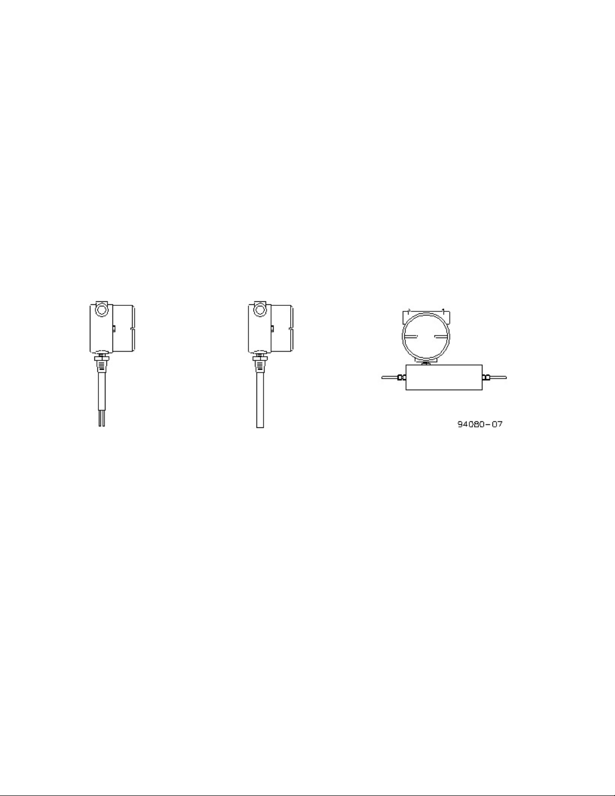
2. TU or TUL (nonintrusive) — TU or TUL transducers particularly require special care in
handling and installing to avoid damage to sensor tube stubs.
.CAUTION: TU and TUL transducers are made with thin-walled tubing — use care when
installing.
All TU and TUL transducers should have straight line input and output sections, typically 20
pipe diameters on the inlet and 6 to 10 diameters on the outlet. If installed vertically, the flow
should be going up through the sensor. Connection in the line is via compression fittings, hose
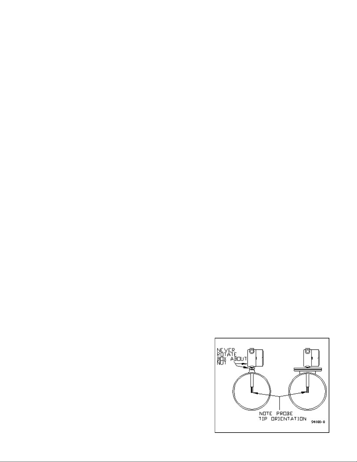
with clamp, threaded fittings or flanges, whichever is appropriate. Care must be taken not to
transmit a twisting force through the transducer's midsection. The TU or TUL transducer,
whether flanged or not, must not be used to pull other piping together or to make up angular
mismatch of fittings. The integral electronics box should never be rotated for any reason.
Flow stream conditioning must also be considered to maximize meter performance. Avoid
upstream protrusions and short distance straight runs. Flow pulsations, such as those created
by metering pumps, may cause the instrument to differ from the factory calibration.
Furthermore, if the flow is varied by stroke and by pump speed adjustment, the indication will
most likely be non-repeatable. If you are using a pump of this type, it is recommended that
a pulsation dampening device be used to provide smooth continuous flow. A second choice
would require readjustment of the instrument calibration (cal) potentiometer after installation
(See SECTION 4.2).
For liquid measurement systems using high pressure gas to force flow, the effects of the
absorbed gas must be considered. In these cases, sudden pressure drops upstream of the sensor
such as line size expansions, control valves, and pressure dropping regulators must be avoided.
Sudden pressure drops can cause the absorbed gas to release into the liquid, making the flow
sporadic and difficult to measure. Control valves should be placed down stream of the sensor.
Fluid temperatures other than ambient require special attention. Thermal gradients from one
end of the transducer to the other (for TU and TUL transducers), as well as along the radius
of the connection pipe, are undesirable. Therefore, effective insulation should be installed
around the inlet and outlet straight line runs. Gradients which may exist in the line further up
stream can be removed if an insulated elbow is installed in the line prior to entering the
straight line portion of the plumbing. Metallic support braces for the sensor or adjoining
plumbing can act as a heat sink and cause operational problems in high temperature
applications. The support braces should be thermally isolated from the line to avoid large heat
conduction effects.
If the transducer is for use above 75/C, it will have an extension arm between the transducer
and the electronics module enclosure. Free air should be allowed to flow around the extension
arm and electronics enclosure to keep the electronics cool. The extension arm can be insulated
up to one-third of its length from the transducer body. Proper thermal control is vital to
accurate meter performance. Non-uniform heat tracing, relay on/off temperature controllers
and oscillating proportional type control should always be avoided. Steam traced lines with
good pressure regulation or properly tuned proportional temperature control systems are

- 7 -
Figure 2. Input Power Selection Jumper Location
effective in maintaining uniform fluid temperature. The ideal installation will provide the
sensor with well established smooth flow, uniform system temperature and consistent fluid
media.
2.2 ELECTRONICS
The standard enclosure for the integral electronics is an explosion-proof cast junction box.
.CAUTION: The electronics are not protected against condensing
liquid water inside the enclosure. If conduit is used, be sure conduit is dry
or sealed at the instrument to prevent conduit condensation from entering
the electronics enclosure.
Unless otherwise specified, normal ambient environment for the electronics is 40-120°F. Recommended
maximum temperature is 135°F.
2.3 ELECTRICAL CONNECTIONS
1. Power — The input power requirement is listed on the tag on the electronics enclosure; make
sure the input power source is compatible. Available input power configurations are 24 Vdc,
24 Vac, 115 Vac, or 230 Vac. The Vac power is ½A, 50-60 Hz, single phase. The power
configuration is pre-set at the factory, but may be changed in the field (except for 115 to 230
Vac conversions). To select either 24 Vac or high voltage (115 or 230 Vac), ensure that power
has been disconnected. Then, remove the electronics module by removing the modular sensor
interface connector and then by pulling the handle on the top printed wiring board (PWB).
Using Figure 2, locate the power select jumper on the lower PWB and simply move the power
select jumper to either the “Lo” (24 Vdc or 24 Vac) or “Hi” (115 Vac or 230 Vac) position.
Do not apply power until the power select jumper position is visually verified.
Wire size no smaller than 24 gauge can be used for power. Fourteen (14) gauge stranded wire
is recommended for the relay contacts. The input power, analog output (for models with that
option), and relay connections are made as shown by Drawing 94080-5 in the back of this
manual. Note the electronics
module is removable for easy
termination of the wires. DO
NOT attempt to install
wiring with the electronics
module in place within the
enclosure. Bend and cut the
wires for a low profile fit,
being careful not to stress
them. Ground the enclosure
with a separate wire. Once
all connections are made,
firmly push the module back
into its base noting the
position of the keying post.
The electronics signal ground
is isolated from the

- 8 -
transducer casing and therefore the analog output is isolated from earth ground. However, if
the power select jumper is set in the “Lo” position, the analog output will not be isolated from
the incoming power line.
Install conduit such that all seals are watertight and rigidly secure. After pulling wire, pot the
conduit near the enclosure if there is any possibility of them trapping water or moisture. The
lid of the enclosure should be on tight enough to make a good seal against the gasket. Ensure
all enclosure openings are completely watertight.
As a general rule, if the flow is to be shut off or the flow line empty for long periods of time,
power to the unit should also be turned off. An on/off switch, provided by the customer, is
recommended for all industrial installations.

- 9 -
SECTION 3 !OPERATION
3.1 START UP
Typically, the instruments come from the factory set up for a 10 to 1 flow rate span, with the trip level
set approximately at 10% of the full scale value. SECTION 6 details the instrument specifications.
Following installation all that is required is to switch on power and initiate flow in the measurable flow
rate range. The following figures and tables show how to configure the Model 400 alarm setpoint(s),
high/low alarming, and time response. Liquid meters that are not calibrated directly on the liquid to be
measured are so indicated in this manual (SECTION 6) and require an in-line field calibration.
When power is first turned on, the output reading or signal will indicate full scale. After ten to forty-five
seconds (depending on flow range adjustment) the reading will stabilize. The instrument time constant
is generally between 4 to 12 seconds. Higher average flow rates will result in an observed faster
response time for a given unit.
3.2 FIELD ADJUSTMENT INSTRUCTIONS
The flow switch/monitor may initially indicate a high flow rate even for zero flow when power is first
applied to the unit. Correct indication of flow or level will result after an initial period which can extend
to about forty seconds depending on where the level adjust is set. Apply power only after reading and
adhering to instructions in SECTION 2 of this manual.
3.2.1 Adjustment of the ALARM1 flow switch setpoint (all Model 400 types)
A. Establish a flow rate at the desired trip level. This should be done with flow in the line, not
at zero flow. Set the alarm switch, S1, to “LO” if alarming at a rate below this flow value is
desired; set it to “HI” if alarming at a rate above this flow value is desired. An example would
be to use 50% of your lowest normal flow rate as the set point and setting S1 to “LO.”
B. If the LED is green, adjust “Trip 1" potentiometer clockwise* until the relay de-energizes
(LED turns red). This is the alarm condition.
C. If the LED is red, adjust “Trip 1" potentiometer slowly counter clockwise* until the relay
energizes (LED turns green).
D. If the relay cannot be made to drop out over the full range of the “Trip 1" potentiometer, see
Table III.
*Reverse direction of turns if S1 is set to “HI” position.
3.2.2 Adjustment of the ALARM2 flow trip setpoint (when S2 option is ordered)
The ALARM2 flow switch is energized at flows below the trip level and does not have an LED to
indicate alarm state. The relay contacts must be monitored to determine the relay state (refer to Table
II). If one relay is to be used for high flow alarm and one relay for low flow alarm, RELAY1 should be
used as the “lo” alarm and RELAY2 used as the “hi” alarm.

- 10 -

- 11 -
Figure 3. Set point Adjustment Components and Locations
A. Establish a flow rate at the desired trip point. The relay in standard flow switches is picked
up (energized) when the flow level is above a set point. A low level is therefore indicated in
the event of loss of power to the sensor when connected to N.C. contacts. Relay 2 will be
energized with flow below the trip level.
B. If RELAY2 is energized, adjust “Trip2” potentiometer counter clockwise until the relay de-
energizes. This is the alarm condition.
C. If RELAY2 is de-energized, adjust “Trip2” slowly clockwise just until the relay energizes.
D. If the relay cannot be made to drop out over the full range of the “Trip2” potentiometer, see
Table III.
TABLE I. Alarm1 Output Configuration (all Model 400 units)
S1 Position NC1 - COM
contacts Relay1 State LED1 Status Flow Rate Liquid Level
LO Open energized Green Above set point Liquid
LO Closed de-energized Red Below set point Air
HI Closed de-energized Red Above set point Liquid
HI Open energized Green Below set point Air

- 12 -
Figure 4. Time Response Selection Jumper Location
TABLE II. Alarm2 Output Configuration (units with S2 option)
S1 Position NC2 - COM
contacts Relay2 State LED1 Flow Rate Liquid Level
N/A Closed de-energized N/A Above set point Liquid
N/A Open energized N/A Below set point Air
The response time of the Model 400 can be changed between two settings: “Slow” and “Fast.” This
change is made by moving the jumper shunt at JP7 (see Figure 4). The unit will usually come from the
factory set in the “Slow” position. Notice that in the “Slow” position, the response is sluggish but noise-
free. The fast response position will cause any alarming to be accelerated, however, it will allow flow
noise to be present in the instrument’s output signal.
In general, when the output signal is being monitored, the “Slow” position is best. When the unit is used
strictly as a flow switch, it may be useful to use the “Fast” setting for gas flow or level monitoring
systems, and the “Slow” position for high velocity liquid flow systems. Figure 5 shows typical response
differences between the two settings.
3.3 GENERAL INFORMATION
The Model 400 instrument is compensated for a wide range of both ambient and flowing media
temperatures. However, abrupt changes in the temperature of the flowing material can cause the
instrument output to deviate from the true representation of flow rate, which in turn could lead to an
inappropriate tripping of the relay or a delay in reading a loss of flow. A proper reading is obtained only
when the transducer is in thermal equilibrium with the material. Typically, a 20°F abrupt change in
temperature may require 40 seconds to stabilize. Temperature ramps should be kept below 1°C/minute.
In general, the heater used in the transducer does not develop enough power to cause damage to the
system in the absence of
flow. This includes those
used in liquids even if the
line becomes empty and is
filled with air. Rheotherm
instruments have additional
circuitry which prevents
overheating in the event of
the loss of flow. This
thoroughly protects the
instrument from damaging
itself. Although it is not
required, it is recommended
that the instrument power be
shut off when the instrument
is not in use. Any special
cases concerning unique
requirements may be
discussed in SECTION 6,

- 13 -
Figure 5. Typical Time Response Characteristics
CUSTOM INFORMA-TION.
3.4 OUTPUT CURVE
If the instrument is ordered with a calibrated
output signal, the output curve for the unit can
be found after SECTION 6. For an
uncalibrated unit with a 4-20mA option, a
typical curve is shown in Figure 6. Check
SECTION 6 for the corresponding full scale
value for this instrument. Flow can also be
found by the formula:
FLOW (%FS) = exp [ exp (0.5547* X + 0.26935 ) ] / 0.1758
where X is the flow output signal in mA.
Figure 6. Typical Output Curve (for units with 4-20mA output option)

- 14 -
SECTION 4 !MAINTENANCE
4.1 GENERAL MAINTENANCE
Certain precautions should be taken to insure proper performance of all models of flow instruments.
Since the measurement technique involves a signal resulting from heat transfer to the flowing medium,
care should be exercised to prevent build-up of varying layers on the walls of the transducer. Layers
such as bacterial growth, dried paints, gas bubbles and non-solubles can result in measurement below
actual flow rates. Periodic checks and cleaning should be performed to insure a clean pipe or probe
surface.
It should be part of normal maintenance procedure to check the system for proper functioning.
Experience and other observable conditions should be utilized to determine the frequency of inspection.
To test the flow switch action, the flow rate should be reduced below (for low flow switch) or raised
above (for high flow switch) the switching level. When the unit reaches alarm mode (de-energized relay,
LED is red), check and insure relay action and continuity of the shut down or warning circuits which it
operates.
The joints of all intrusive probes tips should be inspected for wear and corrosion.
4.2 FIELD CALIBRATION
If the unit was purchased with a 4-20mA output, and calibrated at the factory or by the customer, a field
recalibration can be performed as follows:
1. Establish a known flow rate near 10-15% of the desired full scale value. Monitor the flow
output for stability.
2. Locate the zero potentiometer (pot) labeled P3 using Figure 3. Identify the proper flow output
signal corresponding to the current flow rate (see Figure 6 or the supplied calibration curve,
as applicable). After the flow has stabilized. adjust P3 until the flow output agrees with the
desired output value.
3. Establish a known flow rate near 95-100% of the desired full scale. Monitor the flow output
for stability.
4. Locate the span pot labeled P4 using Figure 3. Identify the proper flow output signal
corresponding to the current flow rate (see Figure 6 or the supplied calibration curve, as
applicable). After the flow has stabilized, adjust P4 until the flow output agrees with the
desired output value.
5. Since potentiometers P3 and P4 are slightly affected by the adjustment of the other, repeat
steps 1 through 4 until the desired accuracy level is achieved.

- 15 -
6. In general, the curve shapes do not change if the zero and span values are set properly. If the
instrument is being re-ranged, simply use a new full scale value and normalize the output
curve to 100%. If extreme nonlinearities exist, such as that of a laminar to turbulent flow
regime transition, a new curve will need to be constructed. Furthermore, if a transition region
exists and the instrument must operate over a range of temperatures, several curves must be
constructed at fixed temperature steps throughout the temperature range to assure best
accuracy.
4.3 SPARE PARTS
There are no normally recommended spare parts to stock. The transducer and electronics boards are
a matched set and therefore are not interchangeable with others. Should a spare be needed, a complete
unit should be ordered and stocked. Spare fuses are ½A fast acting Wickmann fuse, part number
3730500041 or equivalent for 115/230 Vac usage and 1A slow blow Wickmann fuse part number
3741100041 for 24V usage.
4.4 TROUBLE SHOOTING
TABLE III. TROUBLE SHOOTING GUIDE
OBSERVATION PROBABLE CAUSE REMEDY
Flow trip level continually drifting
downward with constant flow.
Coating forming on wetted surface of
transducer.
1. Clean transducer periodically.
2. Adjust span potentiometer
clockwise until layer build-up
stabilizes.
After flow switch has been operating
properly:
Relay incorrectly trips with flow
above or below trip level and cannot
be adjusted using instructions in
SECTION 3.2.
1. Dirty electrical contacts.
2. Bad electronic component
1. Inspect electronics module and
its socket for corrosion. Clean
and replace.
2. Contact factory.
Relay cannot be made to trip by
adjusting trip adjustment
potentiometer(s).
1. Flow rate out of range of
instrument.
2. Flow media change.
1. Refer to SECTION 4.2 on
calibration to re-range the
instrument.
2. Contact factory.
Relay trips on and off, or flow signal
is very noisy but flow is constant and
steady.
1. Flow noise is being amplified
by fast response circuitry.
2. Instrument has been readjusted
or instrument is defective.
1. Move time response jumper to
“SLOW.”
2. Contact factory.
LED is not lit and relay stays in
alarm condition (N.C. contact is
made).
1. No power to electronics.
2. Blown fuse.
1. Check incoming voltage.
2. Replace fuse with appropriate
ampere and time delay rating.
3. Return to factory.

- 16 -
SECTION 5 !CUSTOMER SERVICE
Intek's corporate philosophy is to solve our customer's difficult flow measurement/monitoring problems.
This means that each instrument is custom configured and calibrated for the application. When you
purchase a Rheotherm instrument you also receive Intek's outstanding customer service. For sales or
product service, call your local representative or Intek directly at (614) 895-0301 8AM to 5PM EST/EDT
weekdays or fax us anytime at (614) 895-0319. Our customer service staff will provide assistance
promptly. Our website at www.intekflow.com is available for additional information; for submitting
5.1 QUESTION ON EXISTING HARDWARE
To allow us to help you more quickly, please have the serial number of the equipment available before
you call. If your company is not the original purchaser the identity of the original recipient will also be
helpful.
5.2 TROUBLE SHOOTING
If you have reviewed SECTION 4.3 TROUBLE SHOOTING and have questions, please call our
experienced engineers for assistance. In many cases we can solve a problem over the phone. Please
provide as complete a description as possible of the problems encountered.
5.3 FACTORY AND FIELD SERVICE
Model 400 flow switch/monitor cannot be serviced in the field. If a problem cannot be solved through
a telephone conversation with one of our engineers, the unit should be returned to the factory for
inspection.
To request factory service, a Return Material Authorization (RMA) and purchase order is required. Our
customer service staff will assist you with the required information to return instruments for service.
5.4 DECONTAMINATION OF EQUIPMENT
For the safety of your personnel and ours, any hardware that has been in contact with potentially
hazardous liquids or gases must be properly decontaminated before shipment to Intek.
5.5 QUESTIONS ON NEW EQUIPMENT
For a new Rheotherm application or any liquid or gas flow measurement need, visit us at our website,
www.intekflow.com or contact your local Rheotherm representative or the Intek technical sales
department at the above phone/fax numbers. Our staff will be pleased to answer all questions and
provide quotations.

- 17 -
SECTION 6 !CUSTOM INFORMATION
6.1 UNIT IDENTIFICATION
Model no.:
Serial no.:
Customer identification:
6.2 CONFIGURATION
The configuration of this unit, as originally shipped from the factory:
Input Power:
G20-28 Vdc G20-28 Vac
G100-130 Vac, 50/60 Hz G200-240 Vac, 50 Hz Gother
Maximum Pressure:
GX
Full Scale Flow:
G
Analog Output:
GClamped, current supplying 4-20mA flow output Gnone
Relay Output(s):
GALARM1: SPDT 10A res. 125 Vac
GALARM2: SPDT 10A res. 125 Vac
Wetted Material:
G316 series stainless steel Gother
Enclosure:
GX Class I, Group B, C, & D; Class II, Group E, F, & G; Class III; NEMA type 4X
Process Connection:
Gmale NPT thread Gflanged mount Gother
6.3 SPECIAL INSTRUCTIONS

- 16 -
Table of contents
Other Intek Measuring Instrument manuals
Popular Measuring Instrument manuals by other brands

PT
PT W80158 owner's manual

Brüel & Kjær
Brüel & Kjær 4423 Instructions and applications

Test Equipment Depot
Test Equipment Depot AMPROBE WT-80 user manual

Keysight Technologies
Keysight Technologies N8262A P Series user guide

Water I.D.
Water I.D. PoolLAB 1.0 user manual

LogikaControl
LogikaControl HTR Installation and use manual