Intelbras ICIP 30 Impacta 68i User manual

User manual
Base boards and codec ICIP 30 Impacta 68i

Base boards and codec ICIP 30
Impacta 68i
Congratulations, you have just purchased a product with Intelbras quality and security.
Intelbras, thinking about theseVoIP market needs, offers the ICIP 30 68i solution for the Impacta
68i PBXs, improving their performance and ensuring high availability of calls.
The ICIP 30 68i is an option card based on an IP platform with high customization capabilities
and compatible with the SIP communication protocol. It was designed to be a VoIP networking
solution, allowing telephone communications to be carried out over the available data network,
thus providing a signicant reduction in telephony expenses and an increase in plant exibility
for small and medium-sized businesses.

Summary
1. Technical specications 4
2. Features 4
3. Care and security 5
4. Data protection and security 5
4.1. Handling of personal data ....................................................................5
5. Care and security 5
5.1. Data protection and security ..................................................................5
5.2. Guidelines that control data processing ..........................................................5
5.3. User Misuse and Hacking ....................................................................6
6. Product 6
6.1. Base board ICIP 30 Impacta 68i ................................................................6
6.2. Codec Card Connection ICIP 30 Impacta 68i (1 to 3) ................................................7
6.3. Data protection and security ..................................................................7
7. Product 8
7.1. Technology................................................................................8
7.2. VoIP ....................................................................................8
7.3. ProtocolSIP ...............................................................................8
8. Installation 9
8.1. Technical recommendations ...................................................................9
8.2. Scenario ................................................................................10
9. Management via web browser 10
9.1. Listening to IP addresses ....................................................................11
9.2. Web Programer ...........................................................................11
9.3. System .................................................................................12
9.4. Record..................................................................................12
9.5. Interfaces................................................................................13
9.6. Network ................................................................................13
9.7. VoIP - board ICIP 30 channels ................................................................36
9.8. Maintenance .............................................................................54
Warranty term 56

4
1. Technical specications
Standards
IEEE802.3 Ethernet 10BASE-T
IEEE802.3 Nway Auto Negotiation
IEEE802.3u Fast Ethernet 100BASE-TX
IEEE802.1Q tagged VLAN
IEEE802.1p Layer2/CoS Trafc Priority
IEEE802.3ac VLAN tagging
Network Interfaces 1 UTP fast Ethernet RJ45 10/100 Mbps LAN port
1 UTP fast Ethernet RJ45 10/100 Mbps WAN port
signaling protocol SIP 2.0/SIP Intelbras
Interface USB 1 USB host type A
port USB 1.1/2.0 compatible
VoIP Channels Up to 30 channels (10 channels per ICIP 30 68i codec card)
Voice coding
G.711 PCM (A/u-law) up to 64 kbps
G.729 AB CS- ACELP up to 8 kbps
GSM Full Rate 6.10 up to 13.2 kbps
G.723, G.726-16, G.726-24, G.726-32, G.726-40 (ADPCM)
LEDs Indication of system and codec status
2. Features
» Signal processing support.
» Adaptive and mounted jitter buffer control and packet loss concealment (PLC) technology.
» Digital voice coding - GSM Full Rate 6.10, G.711 PCM (A-law and u-law) and G729AB, G.726 (ADPCM), Voice Activity
Detection (VAD), Comfort Noise Generation (CNG), Echo Cancellation (LEC - G.168-2002, up to 128ms) and Automatic
Gain Control (AGC).
» DTMF signaling (In-Band, RFC 2833 and SIP INFO).
» » Network support.
» » 1 IP extension and 1 IP connector for each VoIP channel, with each codec card having 10 channels (no hardware key
purchase required).
» Up to 30 VoIP channels (using up to 3 ICIP 30 codec card type modules).
» IP connectors: Point to Point and Proxy (VoIP operator).
» Supports up to 5 VLANs.
» 2 UTP Fast Ethernet 10/100 Mbps ports for LAN and WAN.
» Automatic detection of the Intelbras ICIP 30 codec card.
» System monitoring via SNMP (V1/V2c/V3).
» Firmware update for the PABX (Intelbras central ofce, DISA, music, interfaces, and IP telephoneTIP 100 and ATA GKM 2210T).
» Conguration support via web browser (HTTPS).Web programming is compatible with the Mozilla Firefox® browser (see
the compatible version in the Impacta Central Ofces Compatibility Table, available in the Downloads section of our site).
» Firewall system protection.
» Trafc control..
» It allows connection to a Ticketing Machine, E1 Monitor, CSTA, and other applications via ICTI.
» Local and remote log generation (SysLog).
» Registering a dynamic DNS address (DDNS).
» Synchronization of system clocks via the Internet (NTP).
» Local area network (LAN) and external network (WAN) access interface.
» Autoprovisioning for IP extensions with Intelbras TIP 100 telephone and ATA GKM 2210T (as of version 1.3 release 32)
» Automatic initialization of IP phones.
» Automatic update of the extension number of the Intelbras TIP 100 IP/ATA telephone and GKM 2210T ATA.
» Detection of VoIP carrier out of service.
» Indication of priority of messages in relation to others (QoS, IP Precedence protocol).
» Brute Force Attack detection.

5
3. Care and security
The following information is intended for authorized or specialized technicians.
Attention: only technicians trained by Intelbras are authorized to install and congure the PABX, as well as open the box,
connect and handle its interfaces.
Read carefully all information about the equipment and follow all safety information.a.
» Always consult a superior or immediate superior before starting work, informing him or her of the procedures needed to
perform the requested service and the necessary safety precautions.
» Turn off the power to the system when assembling or removing interfaces.
» Connect the grounding conductor to the system involved before you start. Never operate the equipment with the groun-
ding conductor disconnected
To avoid electrostatic damage to the ICIP board, observe the following precautions:
Warning: Static electricity can damage the electronic components of the Interface.This kind of damage can be irreversible
or reduce the life expectancy of the device.
» Use an antistatic wrist strap, or similar, to handle the plates.
» Transport and storage should only be in static-electricity-proof packaging.
» Place the board on a grounded surface when removing it from the packaging.
» Avoid touching the pins of integrated circuits or electrical conductors.
» Always be properly grounded when touching the board or any component.
4. Data protection and security
4.1. Handling of personal data
This system uses and processes personal data such as passwords, detailed call logs, network addresses and customer data
records, for example.
5. Care and security
5.1. Data protection and security
Please observe the local laws regarding the protection and use of data and the regulations that prevail in the country.
The purpose of data protection legislation is to prevent infringements of individual privacy rights based on the misuse of
personal data.
5.2. Guidelines that control data processing
» Ensure that only authorized persons have access to customer data.
» Use the password assignment features, without allowing any exceptions. Never give passwords to unauthorized persons.
» Ensure that no unauthorized person has the means to process (store, alter, transmit, disable or delete) or use customer
data.
» Prevent unauthorized persons from gaining access to data media, eg backup disks or protocol printouts.
» Ensure that data media that are no longer needed are completely destroyed and that documents are not stored or left
in generally accessible locations.
» Working together with the client generates trust.

6
5.3. User Misuse and Hacking
» The passwords to access product information allow any facility to be reached and changed, such as external access to
the company’s system to obtain data and make calls, so it is of utmost importance that passwords are made available
only to those who are authorized to use them, at the risk of misuse.
» The product has security settings that can be enabled, and that will be addressed in this manual, however, it is essential
that the user ensures the security of the network on which the product is installed, since the manufacturer is not respon-
sible for the invasion of the product via hacker and cracker attacks.
6. Product
The product solution that allows access to voice signal transmission technology over the Internet or a private network is
composed of the set:
» » ICIP 30 68i base board: responsible for processing network information, access protocols, and connections to the
client’s network and the Internet
» » ICIP 30 68i codec card: responsible for the VoIP channels available on the ICIP 30 68i base card and for processing
the “voice” signals and converting them into data packets within the network. Each codec card enables 10 VoIP channels.
» Hardware key with extension licenses and IP trunks.
6.1. Base board ICIP 30 Impacta 68i
Slot for codec
USB Host
LAN
WAN
Grounding
Connector for connection to the base board, in position
OPC3/ICIP
Jumpers for recovery
Slot for codec Codec board ICIP 30
Impacta 68i
ICIP: communication Interface

7
6.2. Codec Card Connection ICIP 30 Impacta 68i (1 to 3)
ICIP 30 codec card
Impacta 68i
Jumpers for recovery
Slot for codec
WAN
USB Host
LAN
Grounding
Connector for connection
to the base board at the
OPC3/ICIP position
6.3. Data protection and security
LAN network interface RJ45 10/100 UTP fast Ethernet port for local network access.
USB Ports 2 USB host ports for connecting peripherals
LAN network interface RJ45 10/100 UTP fast Ethernet port for external Internet access connection.
LED indicating the status of the ICIP 30
68i base card
Cadence State
Permanently lit Board not initialized
Flashing very fast (100 ms ON/100 ms OFF) Board booting (Linux idle)
Blinking rapidly (500 ms ON/500 ms OFF) Board booting (Linux active, and services booting)
Moderately blinking (1 s ON/1 s OFF) Board booting and operating (Web Developer Active)
Blinking intermittently (1400 ms ON/300 ms OFF) Board initialization failure
Connectors for ICIP 30 68i codec card There are 3 positions available for connection, thus up to 30 VoIP channels

8
7. Product
7.1. Technology
Overview
With the ICIP board, the Impacta 68i continues to have all the features and functionality already existing, but now incor-
porating the new features already mentioned.
In it, voice-related information will be transmitted over the Internet or a private network through technology known asVoIP
(Voice over IP) using the SIP protocol. So, now, besides being able to use the whole structure of the installed telephone
network, your company can also use the data network to make and receive calls through the SIP phones.
Some of the immediate results are
» Reduction of costs for local, long distance, and international calls, by using the internet;
» Unication of the numbering plan for VoIP extensions, analog and digital;
» Web access to the conguration and administration system;
» Reduction of network operation costs.
7.2. VoIP
Voice Over IP (VoIP) is the technology that allows voice information to be transmitted over the Internet Protocol (IP).This
concept consists of digitizing the voice, packaging it, and transmitting it over the same network that is used to transport
the IP data packets.
The packaging consists of inserting the samples or frames processed by the encoder (codec) into packets. These packets
travel on the IP network through routers, which make the decision by receiving the packets and choosing the most conve-
nient routes to the recipients.
7.3. ProtocolSIP
It is a protocol used to establish calls and conferences over IP networks. It was designed with simplicity in mind, and as a
session establishment mechanism, it only starts, ends and modies the session, which makes it a protocol that ts comfortably
on different architectures.
SIP plays an increasingly important role in IP telephony, mainly because of its simplicity, exibility, security, ease of mobility, and
especially because of the wide acceptance by manufacturers of IP PBXs, gateways, and IP phones.

9
8. Installation
To mount the base board and ICIP 30 68i codec, follow the procedure:
1. On a grounded surface connect the antistatic wrist strap;
2. Remove the ICIP 30 68i base board and the ICIP 30 68i codec board(s) from their packaging and place them on the
grounded surface;
3. Check the condition of the boards and their connectors;
4. Stably support the ICIP 30 68i base board on the surface and insert the ICIP 30 68i codec board(s) in the available
positions, as shown below;
5. Insert the assembled assembly into antistatic packaging until the central ofce is ready to receive it;
6. Inform a person responsible for the Impacta central ofce that it will be necessary to turn it off;
7. Find the network administrator or IT technician to help you recognize in which scenario the ICIP card will be congured,
write down the IP addresses, broadband servers, SIP Proxy server, users and passwords, as well as the physical location of
the LAN and WAN network cables (you should preferably use theWAN port to connect to the customer’s internal network
and the LAN port to connect to the SIP Trunk provider’s internal network);
8. Turn off the AC power to the Impacta 68i switchboard and remove the cover;
9. The ICIP 30 68i base board must only be connected in the OPC3/ICIP position (CN2);
10. Connect the LAN and WAN network cables to the respective connectors;
11. Organize and identify the network cables along with the other cables in the switch DG;
12. Before putting the system into service, a visual check of all cable connections, modules, boards, and AC power should be
performed, and any faults should be corrected.
13. The visual check should be performed with the system turned off;
14. Replace the cover and turn on the Impacta’s AC power;
15. After booting the system, check, through the Web Programmer / Menu Interfaces / Board Disposition, if no board is
programmed to use that slot;
16. Program the necessary data through the Web Programmer.
8.1. Technical recommendations
This system uses VoIP (voice over IP) technology, and the quality of its operation depends on the trafc conditions and
prioritization of the network to which the product is connected. In order for the audio quality of the switch to be excellent,
the network where all packet trafc is transmitted/received must have sufcient bandwidth. In case of abnormalities in the
established calls, such as audio problems, check rst the network situation with the VoIP provider
The information that should be analyzed with the ISP is:
» Minimum guaranteed (%) contracted bandwidth: The contracted speed represents the maximum speed congured within
your ISP’s network. Most Internet providers guarantee a minimum speed of 10% of the contracted bandwidth (between
user and provider) within their network.
» Network latency: is the time it takes for a packet to travel over the network, from its source to its destination.
» Download Speed: is the speed at which packets are received from the Internet.
» Upload Speed: is the speed at which packets are sent to the Internet. Internet providers often offer upload speeds that
are less than or equal to download speeds..
» Check the number of computers on the network
» Consult your VoIP provider about which codecs (voice encoder/decoder) to use and the settings that you need on your
system for best voice quality.
» Fax sending or receiving depends on the quality of your Broadband Internet signal, latency, packet loss rate, and the pre-
sence of the necessary protocols at the destination. Therefore, the proper functioning of the Fax can only be guaranteed
if these conditions are favorable.
» It is recommended to congure the system so that there is no transcoding at SIP extensions. (see Codec guide)
» For IP extensions to work properly the DTMF send mode must be SIP INFO (see the General VoIP tab in the Web Pro-
grammer).
» The address of the congured DNS server should preferably be from a device belonging to the same network.Accessing a
DNS that is external to the network can cause registration problems for joiners and extensions, slowing down the system.
It is recommended to use DNS servers with fast response times.
10
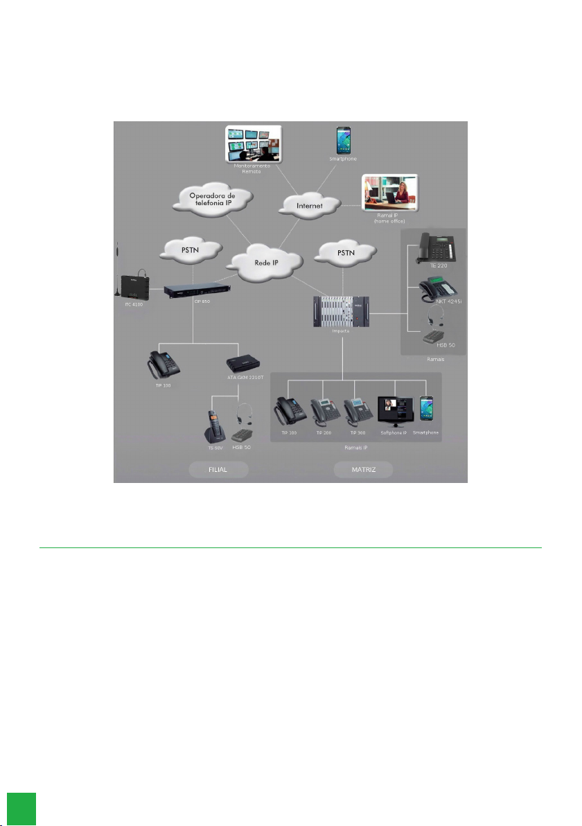
8.2. Scenario
There are many scenarios of application of this new VoIP/SIP technology in conjunction with the Impacta 68i switches. See
below a classic scenario, in which we can visualize several environments connecting through the ICIP card, with codec
card and Licenses.
Scenario
9. Management via web browser
With the installation of the ICIP card in Impacta switches, the management of the entire system can be accessed via the
Mozilla Firefox ® web browser (see the compatible version in the Impacta Switchboard Compatibility Table, available in
the Downloads section of our website).
Attention: to access the Web Programmer interface, congure the management computer with an IP address and subnet
mask that are on the same LAN network as the switchboard.
LAN Factory Default:
» IP address 10.0.0.2
» Subnet mask 255.255.255.0
» Default gateway: 10.0.0.1
» Send Log: 10.0.0.3

11
9.1. Listening to IP addresses
The ICIP card can be congured to get its IP address automatically, via DHCP. In this case the PBX provides a way for the
user to listen to the obtained IP address. The user, using a telephone, must type the following commands:
» *60993*, to listen to the WAN IP address
» *60992*,to listen to the WAN netmask
» *60991*, to listen to the LAN IP address
» *60990*to listen to the LAN netmask
» *60989*, to listen to IP address VLAN1
» *60988*,to listen to netmask VLAN1
» *60987*, to listen to IP address VLAN2
» *60986*,to listen to netmask VLAN2
» *60985*, to listen to IP address VLAN3
» *60984*,to listen to netmask VLAN3
» *60983*, to listen to IP address VLAN4
» *60982*,to listen to netmask VLAN4
» *60981*, to listen to IP address VLAN5
» *60980*,to listen to netmask VLAN5
For manual setting of IP number and netmask, for LAN and WAN, via regular phone:
» LAN - *14 + IP(10*1*30*17) + # + Mask (255*255*255*0) + # + GW(10*1*30*1) + #
» WAN - *15 + IP(10*1*30*17) + # + Mask (255*255*255*0) + # + GW(10*1*30*1) + #
Note: GW (gateway) conguration is not required. You can only set the IP and the Mask. To do this, simply stop at # after
entering the mask and wait for the programming message to be accepted.
Attention: the control panel will restart right after accepting the command.
Open your web browser and enter the address of the ICIP card in the address eld, for example IP 10.0.0.2.
IP address in the browser
A login pop-up window will open (if it does not, clear your browser’s cache or check if there is some kind of pop-up blocker
or other such product active on your computer). Enter the User name and Password for the authentication. The factory
default is:
» User: admin
» Password: admin
9.2. Web Programer
After the authentication procedure the home screen will be accessible to the administrator. Select the desired item from
the left side menu and to access each of the management options.
Attention: the process of creating and conguring IP extensions and junctions is similar to that of analog extensions and
trunks, in the same Conguration>Ports menu.
The same analogy occurs for IP Stations and Trunks Routing conguration, in the Conguration>Routing menu.
The menus of the Web Programmer remain the same as in the PC Programmer, however new menus have been created
for the conguration of the ICIP card, as follows.
12
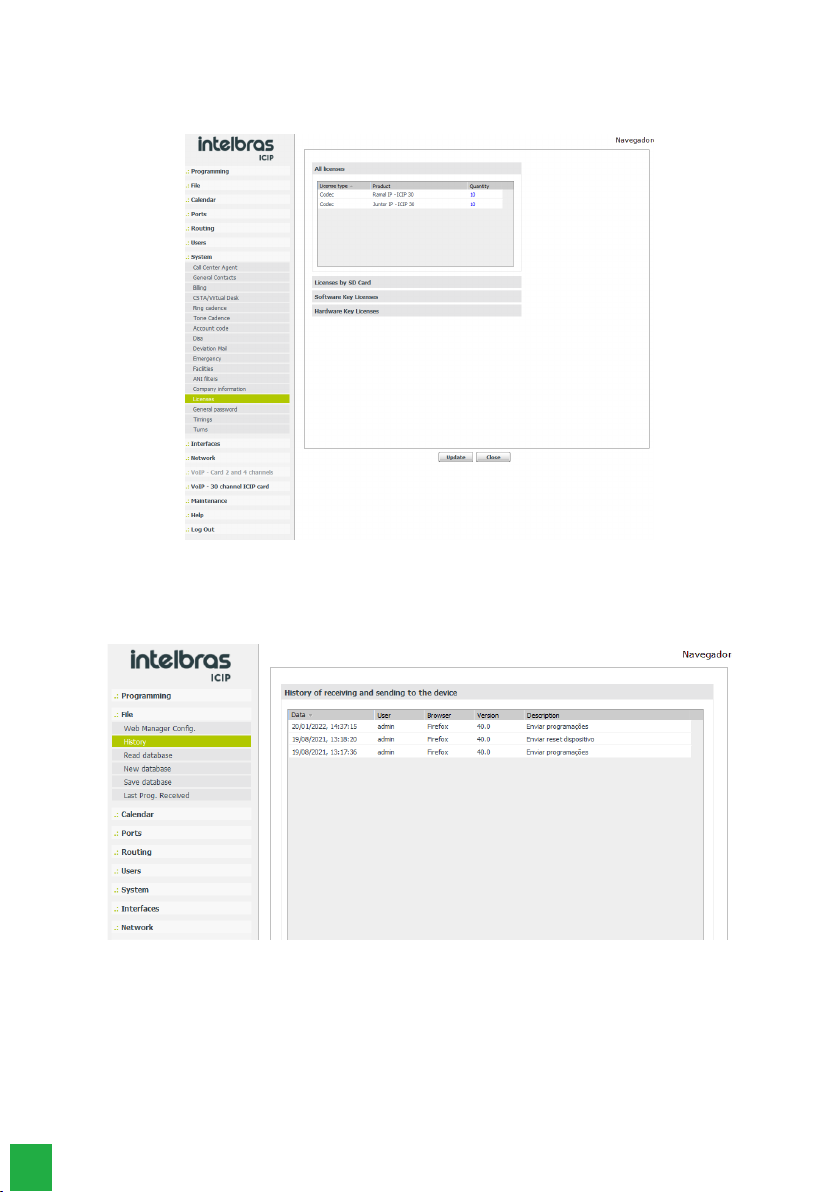
9.3. System
Licenses
Accessing this submenu displays the status and number of valid licenses for IP extensions and IP connectors.
Viewing/conrming licenses
9.4. Record
Accessing this submenu will display the log records of some operations performed by the users.
» Date: Displays the date and time when the operation occurred.
» User: name of the user who performed the operation.
» Browser and version: name of the browser and the version used to perform the operation.
» Description: describes the operation performed. The operations that generate a log are: Send and Receive schedules,
Send rmware, Send reset, and Send database.

13
9.5. Interfaces
Board layout
Accessing this submenu will display a diagram with the quantity and the devices connected to the backplane slots. Check
that the type of ICIP board installed is displayed in the correct slot, if not, you will need to congure it.
1. Select from the card menu the “Empty” option or press the Clear button to leave all slots as “Empty”.
2. Conrm this operation;
3. Select the ICIP 30 base board for that slot (in this example 30 channels).
Localization/upgrade for ICIP 30 68i base board
9.6. Network
Allows you to congure the addressing data, security parameters and services required for the ICIP card to communicate
and be recognized by the local network, as well as the information for the IP connection to the Internet.
Please note: some of this information can be obtained from your network administrator or IT technician.
Network Menu and its settings

14
General
This submenu presents general information about the network and the parameters available for conguration, distributed
in the following tabs:
Network Menu/General Menu
General
Displays the physical card information to the administrator.
Network Menu/General/Submenu Menu
» Board type: tells you what type of board is installed in the system.
» Slot: tells you which slot on the backplane the card is located in.
Enable VLAN
This section allows you to enable VLAN conguration. Enabling this item will have a direct reection on the Network Menu,
where the equivalent submenu for conguration will be enabled. For more details on this service, please refer to the VLAN
section in this manual.
Network Menu/General Sub-Menu/Enable VLAN
» Enable: enables the VLAN item for service conguration and allows you to select how many VLANs will be available in
the ICIP network.
» Number of VLANs: denes the number of VLANs that will be available to the system network. Up to 5 VLANs are
possible.
Outbound interface for trafc
You dene which network interface (LAN, WAN or VLAN) will be used for outgoing system trafc as the default route.
Network Menu/General Submenu/Outbound Interface for Outbound Trafc
From the drop-down menu, select the network interface to be used for outgoing trafc.
15
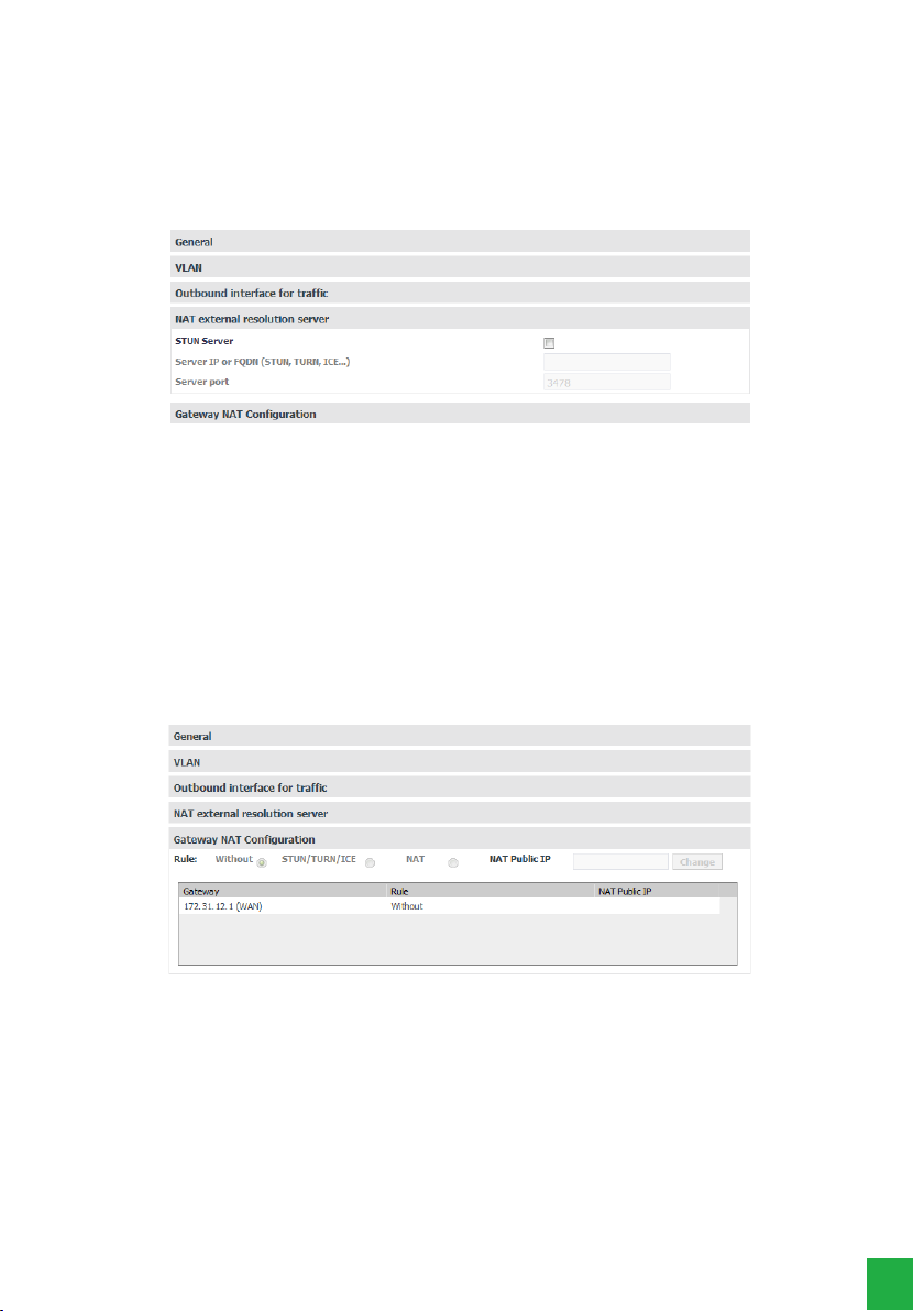
External NAT Resolution Server
STUN (Simple Traversal of User Datagram Protocol (UDP) via Network Address Translators (NATs)) is a server that allows
NAT clients (e.g. rewall-protected computers) to make phone calls to a VoIP provider that is outside the local network.The
STUN server allows clients to nd out their public address, the type of NAT used, and the side of the Internet port associated
with NAT with a specic local port. This information is used to enable UDP communication between the client and the VoIP
provider, and then to establish the call. It expects connections only on the WAN Interface, on port 3478/UDP and 3479/UDP
(Default ports). The STUN server is enabled from the Network>General>Enable Services>STUN Server menu.
Network Menu/General/Submenu Menu/Outside NAT Resolution Server
» STUN Server: enables the use of this feature.
» Server IP or FQDN (STUN,TURN, ICE): Denes the IP address of servers that help the switch maintain communication
with devices that are outside the local network.
» Server Port: Sets the STUN server port.
NAT conguration per gateway
Note: NAT settings are only available for the WAN network interface, you are not allowed to congure NAT on any inter-
face other than the WAN. Preferably congure the LAN interface to access the proxy carrier and avoid connection problems
in a scenario that uses NAT.
You can congure NAT options for all possible ICIP gateways, for example primary and secondary LAN and WAN, 3G. You
can make different NAT settings for each gateway, not only the default routes, but also the static routes.
Network Menu/General Sub Menu/Gateway NAT Setup
For each gateway you can dene:
Rule:
» Without: does not do NAT treatment.
» STUN/TURN/ICE: uses the external STUN/TURN/ICE server, if one is congured.
» NAT: enables you to congure the NAT Public IP eld.
» NAT Public IP: Sets the address, IP or FQDN, that the router is using on the Internet.
16
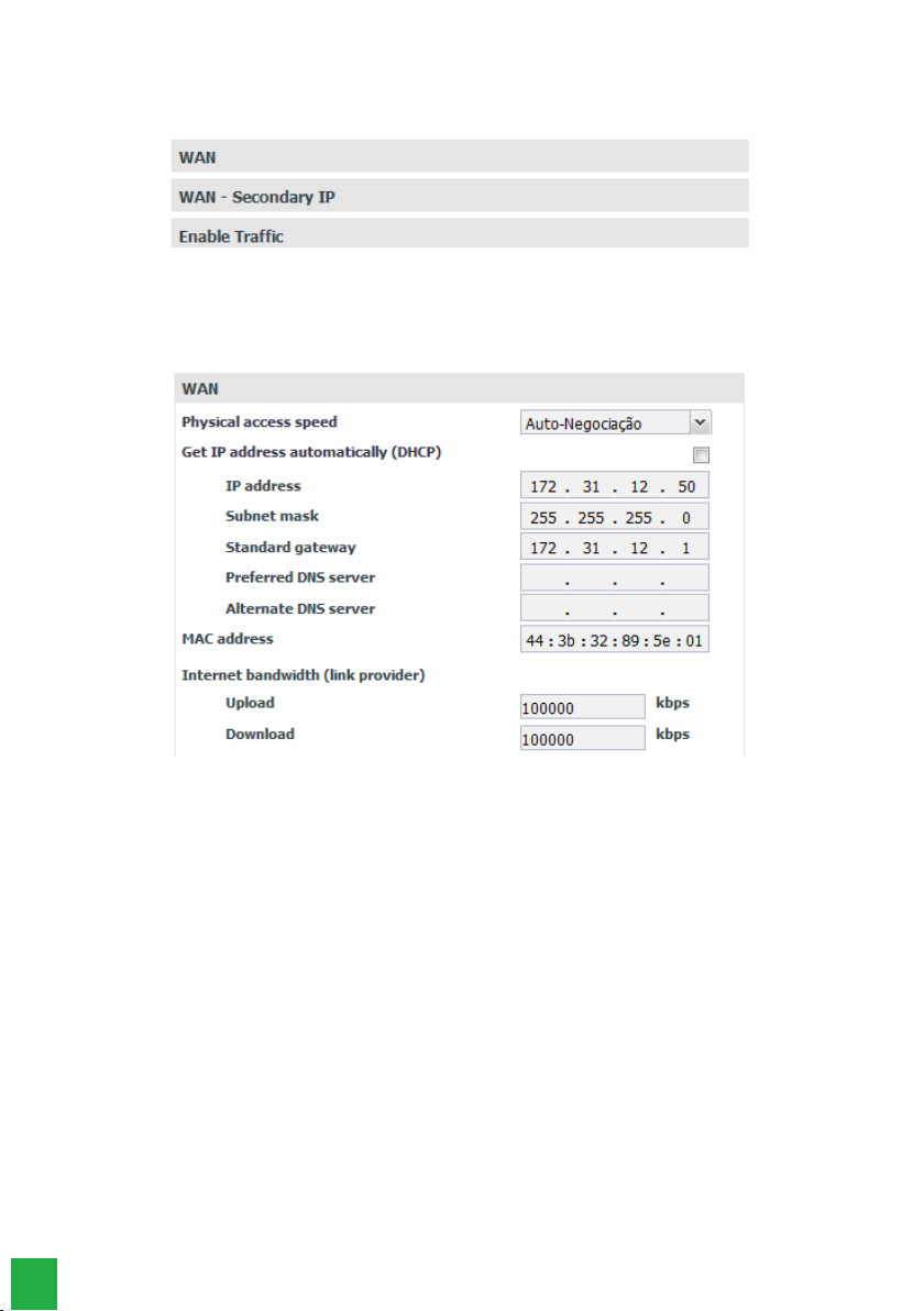
WAN
This submenu presents the WAN interface connection information and the parameters needed to congure it within the
network, distributed in the following tabs:
Network Menu/WAN Sub Menu
WAN
This allows you to congure the physical connection and addressing parameters for the WAN interface, so it is important
to check with your network administrator and ISP for the necessary data. .
Rede/Submenu WAN
» Physical medium access speed: denes the speed of the transmission mode (Auto, Full Duplex or Half Duplex) of
data packets in the network, and is directly related to the existing devices in the network (cables, hubs, etc). Thus the
Autonegotiation option is recommended, if there is no indication from the network administrator.
» Obtain IP address automatically (DHCP): This provides two options for accessing the WAN network:
» Selected, the WAN network access will be dynamic, i.e. information such as IP address, netmask, gateway IP, and DNS
server IP will be provided by the rst network device that implements a DHCP server. This equipment can be a modem,
router, switch, or a computer/server connected to the network.
» Without selection, access to the WAN network will be static, i.e. you will need to ll in the IP Address, Netmask,
Gateway IP, DNS server IP, and upload and download speeds, according to your network administrator’s specications.
» IP Address: Sets the IP address of the WAN port on the network to which the card will be connected.
» » Subnet Mask: Sets the value of the subnet mask where the card will be connected.
» » Default gateway: enter the IP address of the network’s outgoing router (equipment that links more than one physical
network).
» Preferred and alternate DNS server: Enter the IP addresses of the DNS (Domain Name System) servers of your
choice.
Note: it is quite common in small to medium size networks for this IP address to be the same as the gateway address.
» MAC address: Enter the MAC address for the WAN interface, if required. This is typically useful as some ISPs only allow
authentication with the previously specied MAC address. In other cases you must use the same MAC address as the
computer that was authenticated with the ISP.
» Upload and Download: the maximum rates for the connection to the provider are dened as a function of the con-
tracted link. It is important to know the upload and download rates with the available WAN interface, to be able to keep
the link connection balanced and avoid any saturation and consequent loss of quality.

17
Enable Trafc
SIP signaling packet trafc, RTP (regarding voice trafc) and administrative trafc on the WAN network are enabled.
Network Menu/SubMenu WAN/Allow Trafc
» SIP: enables trafc from SIP signaling packets to the congured WAN network.
» RTP: enables the trafc of RTP signaling packets over the WAN network by providing a uniform means to transmit data
subject to real-time “issues” (audio, video,…).
» Administration: enables administration trafc on the WAN network. This can be used to prevent unauthorized people
from accessing the administration settings.
QoS
Allows you to specify priorities for packet or trafc class. QoS seeks to improve the quality of communication by prioritizing
some types of data over others, according to a previous classication of the same, and becomes extremely useful in condi-
tions of trafc congestion on the outgoing interface of this data (for example, the router connection port to the Internet).
Attention: the ICIP card marks data packets, and network assets (switches and routers) must give priority to voice trafc.
Menu Rede/SubMenu WAN/QoS
Enable Layer 3 QoS
In the elds indicated on this screen you have the option to select two packet signaling modes (DSCP or TOS) and their
priority. These parameters will be used for QoS and are inserted in the IP header of all transmitted SIP, RTP and adminis-
tration packets
The choice between modes depends on an analysis of the network, the compatibility of the devices with the selected mode,
and how routers and switches are congured to prioritize trafc.
DSCP (Differentiated Services Code Point) mode prioritizes the packet according to the marking on the received packet.
These packets are distinguished into trafc class according to the delay, processing rate, and reliability information
attached to the packet. For this, it uses 6 bits of the header, giving 64 different possibilities for priority codes.
In TOS (Type of Service) mode, packets entering the network via ICIP are forwarded according to the dened priority.
This uses 3 bits of the header, giving 8 different possibilities for priority codes, 0 being the lowest priority.
The higher the value, the higher the priority in the treatment and use of the network resources.
18
Caution!
» DSCP and TOS modes will come into operation, according to the behavior dened by the IETF.
» When the rate of incoming trafc to a network device is higher than the rate of outgoing trafc (bandwidth), network
congestion occurs. During these conditions, frames marked with higher priority receive preferential treatment and are
delivered before frames with lower priority.
» Remember that it is based on these parameters that network equipment prioritizes voice trafc over data trafc.
SIP
Next to the SIP eld you can select the QoS mode:
» TOS with a value from 0 to 7, which represents the priority of the packet.
» DSCP with a value from 0 to 63, which represents the priority of the packet.
RTP
Next to the RTP eld you can select the QoS mode:
» TOS with Value from 0 to 7, which represents the priority of the packet
» TOS with Value from 0 to 7, which represents the priority of the packet.
Administrator
Next to the Administration eld you can select the QoS mode:
» TOS with Value from 0 to 7, which represents the priority of the packet
» TOS with Value from 0 to 7, which represents the priority of the packet.
Please note: changes made are only valid on devices that are congured in the same way, otherwise trafc will be forwar-
ded according to IETF default behavior or according to some specic conguration on the next device
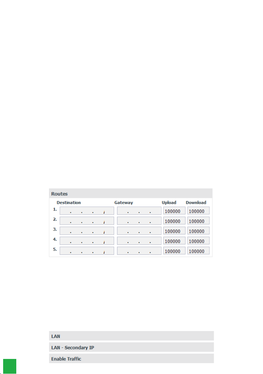
Routes
This setting allows you to dene specic routes to subnets on the WAN, creating predetermined paths where information
can be directed to a specic host or other network.
Menu Rede/Submenu WAN/Routes
» Destination: the IP addresses and mask (IP addresses/net-mask type CIDR) of the routing destination are entered.
» Gateway: enter the IP address of the router, through which trafc will ow to the destination subnet
» Upload and Download: the maximum rates for the connection to the target interface are set. It is important to know
the upload and download rates with the available target interface, to be able to keep the link connection balanced and
avoid any saturation and consequent loss of quality.
LAN
This submenu presents the connection information of the LAN interface and the parameters needed for its conguration
within the network (same as for the WAN), distributed in the following tabs::
Network Menu/WAN Sub Menu

19
Secondary IP conguration for LAN and WAN
The Secondary IP setting allows you to congure a different network than the main one, for both the LAN and the WAN
interface. This makes it possible to switch between different networks just by changing the port where the ICIP cable is
plugged into the switch.
Note: these networks do not work simultaneously. For example: The primary LAN interface is congured with network A
and the secondary LAN interface is congured with network B. If the network cable is connected to network A, the settings
of the primary LAN interface apply. If the network cable is connected to network B, the settings on the secondary LAN
interface apply.
Secondary IP conguration for LAN and WAN
DDNS
With DDNS (Dynamic Domain Name System) it is possible to link the switchboard to an Internet domain name (DNS
address). This is useful, for example, when the central ofce has no xed Internet address.
Before you set up this service, create a DDNS service account at a DDNS provider such as www.no-ip.com. The DDNS
service provider will provide you with a login and password after registration
Menu Rede/SubMenu DDNS
DDNS - Default Route
Allows conguration of the DDNS server parameters. For correct operation, all elds must be congured. Therefore, it is
important to consult the network administrator to obtain the necessary data.
Network Menu/SubMenu DDNS/DDNS
» Address: Enter the IP address or name registered in the DDNS servers, e.g. icip.dyndns.org.
» Server: Denes the server to be used (No-IP, DynDNS).
» Enable DDNS for the default route: Enables updating the DDNS server for the outgoing interface to the Internet.
» Login: enter the user login for the DDNS server.
» Password: Enter the user password for the DDNS server.

20
DDNS - Congurações gerais
DDNS - General settings
» Server Update Time (sec): Sets the time to update the information on the DDNS server.
Please note: to get the IP address that the card has available on the Internet, this service queries via HTTP a server on the
Internet which returns the IP address that the card has accessed the Internet.This is why it is necessary for the ICIP to have
unltered Internet access on port 80, this includes lters such as rewall and authenticated proxy.
DHCP Server
DHCP, Dynamic Host Conguration Protocol, is a TCP/IP service protocol that provides dynamic conguration of endpoints,
granting host IP addresses, Subnet Mask, Default Gateway, and more. The ICIP card has a built-in DHCP server. The main
reason is that it is possible to auto provision the SIP server address to the IP phones.
This feature is not enabled from the factory.
DHCP Server
» Enable: enables the DHCP server.
» Primary DNS: Sets the IP address of the primary DNS server.
» Secondary DNS: Sets the IP address of the secondary DNS server.
» NTP Server 1: Sets the IP address of NTP server 1.
» NTP Server 2: Sets the IP address of NTP server 2.
» NTP Server 3: Sets the IP address of NTP server 3.
» Grant Time (in seconds): Sets the time in seconds that IP addresses are granted.
» Authoritative: Denes whether the server is authoritative.
» Enable DHCP for LAN interface: enables the DHCP server for the LAN interface.
Other manuals for ICIP 30 Impacta 68i
1
Table of contents
Other Intelbras Network Hardware manuals


Popular Network Hardware manuals by other brands


Siemens
Siemens SIMATIC NET SCALANCE W774-1 operating instructions

ADC
ADC Plug-and-Play Cassettes RMG Spec sheet

Fidelis
Fidelis Deception Decoy Server FDH-1000-C quick start guide

Trilliant
Trilliant SP-5 series Installation and setup

Motorola
Motorola Starline SG 2000 Installation and operation manual

Unex
Unex OBU-300 quick start guide


