Intellian i6 User manual

i6/i6P/i6PE
Installation and Operation
User Guide
Document Number: 2012G4-UM1004-V1_0

2
Intellian Satellite TV Antenna Systems
Intellian i6/i6P/i6PE Serial Number
This serial number will be requested for all troubleshooting or service Inquiries.
Notice
All Right Reserved
Intellian i6/i6P/i6PE®is the registered trademarks of Intellian Technologies, Inc., and should not be appropriated without permission by Intellian Technologies,
Inc., and the information contained in this manual is the property of Intellian Technologies, Inc. Any and all parts of this manual shall not be reproduced and
distributed in any form without prior written consent by Intellian Technologies, Inc. The information contained in this manual shall be subject to change at any
time without notice due to the functional upgrades of the product.

3
INTRODUCTION
INTRODUCTION TO INTELLIAN
i6/i6P/i6PE
FEATURES OF INTELLIAN
i6/i6P/i6PE
BASIC SYSTEM CONFIGURATION OF INTELLIAN
i6/i6P/i6PE
INSTALLATION
SYSTEM COMPONENTS
TOOLS REQUIRED FOR INSTALLATION
PLANNING THE INSTALLATION
INSTALLING THE ACU
ACU DIMENSIONS
CONNECTING THE SYSTEM TO A GPS
ADJUSTING THE LNB SKEW ANGLE (LINEAR POLARIZATION ONLY)
OPERATION INSTRUCTION
INTRODUCTION
OPERATING THE ACU
ACU SOFT KEYS
NORMAL MODE
SETUP MODE
OPERATION USING PC CONTROLLER PROGRAM
INTRODUCTION
PROGRAM INITIALING AND SERIAL PORT SETUP
MAIN MENU
CONTROLLER MENUS
PREPARATION FOR TRANSPORTATION
WARRANTY
APPENDIX : I6/I6P TECHNICAL SPECIFICATION
APPENDIX : I6PE TECHNICAL SPECIFICATION
4
4
5
6
7
7
10
11
17
17
22
23
25
25
25
25
26
29
50
50
51
52
54
63
64
65
66
Table of Contents

4
Intellian Satellite TV Antenna Systems
Introduction to Intellian i6/i6P/i6PE
Intellian i6/i6P/i6PE is a digital satellite antenna system designed
specically for all types of vessels (Anchored or transit) to automatically
identify, track and capture satellite signals from the Digital Video
Broadcasting (DVB: the international standard for digital TV
transmissions) compatible satellites.
Specically, Intellian i6/i6P/i6PE has Wide Range Search (WRS)
algorithm, which minimizes the search time during initialization, and
Dynamic Beam Tilting (DBT) technology, which dynamically shapes the
antenna beam to utilize stabilization. While tracking the target satellite,
DBT technology uses a high-performance, constantly adjusting sub-
reector which allows the antenna to remain relatively still, eliminating
the constant whine of stepper motors while staying locked on to the
satellites.
The i6/i6P/i6PE has a built-in GPS system which enhances the speed
of satellite signals acquisitions. The i6P/i6PE has an embedded auto
skew angle control system to maintain the optimal signal strength
and increase the quality of satellite receptions in weak satellite single
coverage area. In addition, the i6PE has a wider elevation angle range
from -15° ~ 90° which enables the system to receive satellite signal at
polar regions.
Introduction
Features of Intellian i6/i6P/i6PE
Enjoy satellite broadcasts at sea
Intellian i6/i6P/i6PE is the most modern antenna system that enables
you to receive a high quality broadcasting signal at sea.
High quality antenna
High tech parabolic antenna technology has been adopted for this
antenna system, which is optimal for marine conditions. This enables
you to receive the optimal signal level even when it is raining or
snowing.
Fast and efcient search for the satellite
The WRS (Wide Range Search) algorithm allows for the antenna
system to search the satellite within the shortest amount of time and
to detect the satellite signal under any position and with any directional
movement of the ship.
Easy installation and outstanding reliability
Intellian i6/i6P/i6PE uses only one RF cable for installation. Power,
RF and Data signals transfer from the antenna the ACU through this
single cable. In addition, the i6/i6P/i6PE provides highly reliable system
through the implementation of a modularized design, and the usage of
strictly proven components.

5
Built-in GPS
Intellian i6/i6P/i6PE has an embedded GPS, which allows for the system
to upload the GPS data automatically into the system for an even faster
and stable system.
Built-in automatic skew angle control system
The automatic skew control system allows Intellian i6P/i6PE to maintain
the optimal skew angle at all times and ensure maximum level of
satellite signal level.
Wide elevation angle
Intellian i6PE is primary designed for receiving satellite signal at polar
regions with its wide elevation angle design. With an extra pointing
angle, the i6PE can track satellite from -15° to +90° elevation.
6
Intellian Satellite TV Antenna Systems
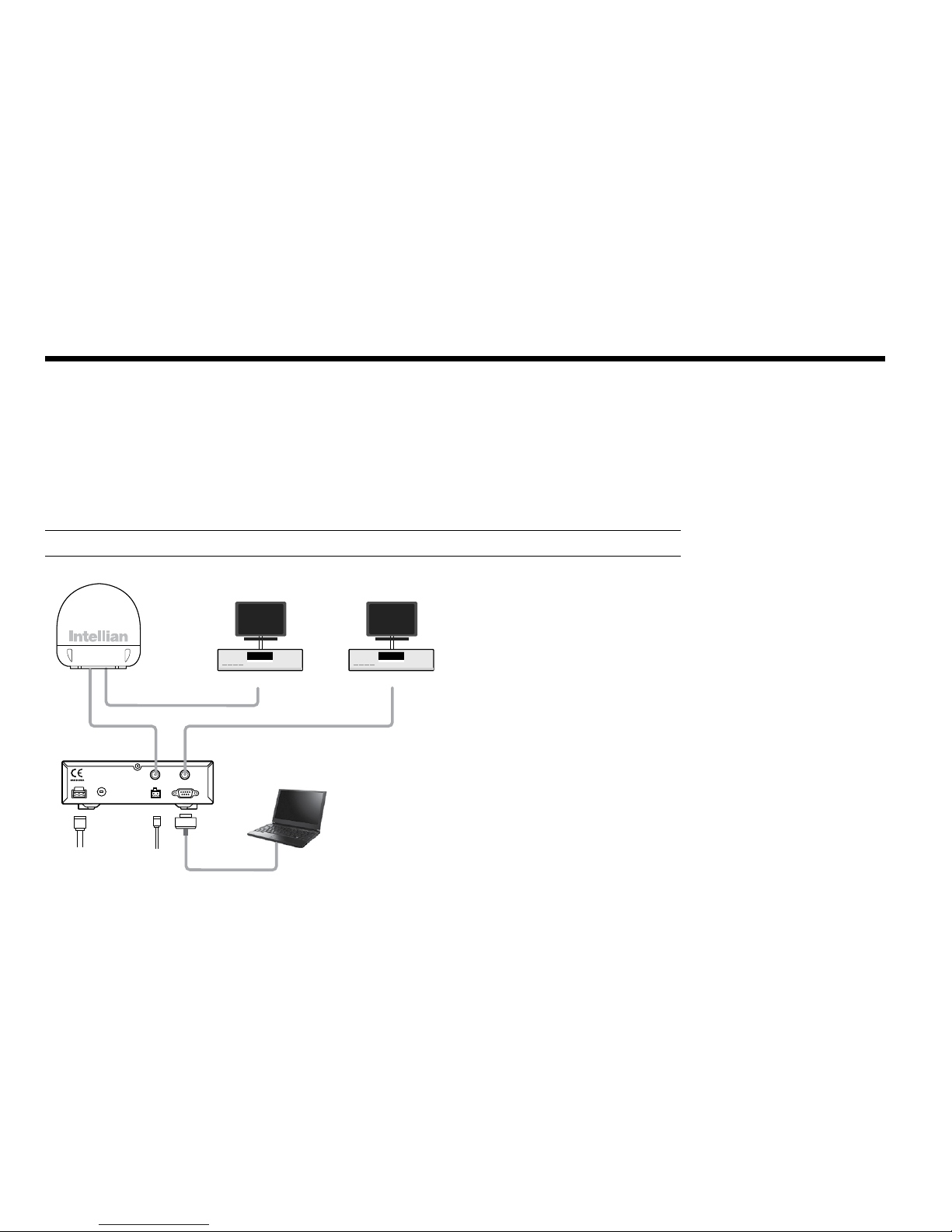
Figure 01 : Basic System Conguration
Basic System Congurations
For your satellite TV system to work properly, the system will have to be connected with all of the provided components
properly, as shown in the gure below (see the “Installation” section of this manual). Separate purchase of a satellite
receiver and a TV is required.
Note: Dish and Bell TV users please refer to the Intellian Dish MIM Installation and User Manual.
ACU
9-30V DC Power NMEA GPS PC Cable PC (Not supplied)
Satellite Receiver (Not supplied)
TV (Not supplied)
Satellite Receiver (Not supplied)
TV (Not supplied)
NMEA
ANT RF1 RECEIVER
FUSEDC 9 - 30 V PC INTERFACE
FG - +
+ -

7
Figure 02 : Antenna Unit
System Components
Antenna Unit
The antenna of Intellian i6/i6P/i6PE is manufactured with the following
components for the optimum search and reception of the satellite signal.
Mechanical Unit – manipulates the antenna to receive the optimal satel-
lite signal regardless of the movement of the vessel.
• Control Unit – controls mechanical operation of the antenna.
• RF Unit – transmits the optimum satellite signal to the receiver.
• Radome – protects the antenna from the severe marine environ-
ment.
Installation
The components of the Intellian i6/i6P/i6PE have been designed to be
modular enabling simple installation on all types of vessels.

8
Intellian Satellite TV Antenna Systems
Figure 03 : Antenna Control Unit (ACU)
Antenna Control Unit (ACU)
Antenna Control Unit (ACU) provides the power to the antenna and con-
trols the various settings of the antenna. Additionally, Vacuum Fluores-
cent Display (VFD) allows for you to operate the ACU in the dark.
The functions of ACU are as follows:
• Provide power for the antenna unit
• Monitor the antenna status
• Change the target satellite
• Set up the user environment
• Set the current GPS information
• Set satellite information
• Move antenna manually
• Perform self-diagnosis of the antenna
• Set up the interface with a PC
NMEA
ANT RF1 RECEIVER
FUSEDC 9 ~ 30 V PC INTERFACE
FG - +
+-
Front
Rear

9
Installation Kit
Contains the items required for securing the antenna unit and ACU to the vessel.
Other Components
Figure 05 : List of the Supplied Parts
Figure 04 : Installation Bolt Kit
4 Power Cable 10m 1
5 PC Serial Cable 1.8m 1
6 NMEA Connector AK950-2 1
7 Power Connector AK950-3 1
8
Hex Bolt M8x50L 5
Hex Head Wrench Bolt M6x35L 5
Self-Tapping Screw ø4x16L 5
ø3x8L 5
Flat Washer M8 5
Spring Washer M8 5
Nut M8 5
9 Install CD - 1
10 Manual - 1
11 Mounting Template - 1
12 Quick Installation Guide - 1
No Components Size Qty
1 ACU Bracket - 2
2 RG6
(Antenna - ACU RF Cable) 15m 1
3 RG6 (ACU - IRD Cable) 3m 1
Hex.Bolt
5
Hex.Head
Wrench Bolt
5
Flat Washer
5
Hex. Nut
5
Spring Washer
5
Antenna
Item
Qty
ACU
Item
Qty
Size
Self-Tapping Screw
5
(M4 X 16L)
Machine Screw
5
(M3 X 8L)

10
Intellian Satellite TV Antenna Systems
Tools Required for Installation
Figure 06 : Required Tools for Installation
Power Drill 11 mm Spanner
Cross-Head
Screwdriver 13 mm Spanner
10 mm Drill Bit
Ø80 mm
Hole Saw
Pencil
5 mm
Allen/Hex key
11
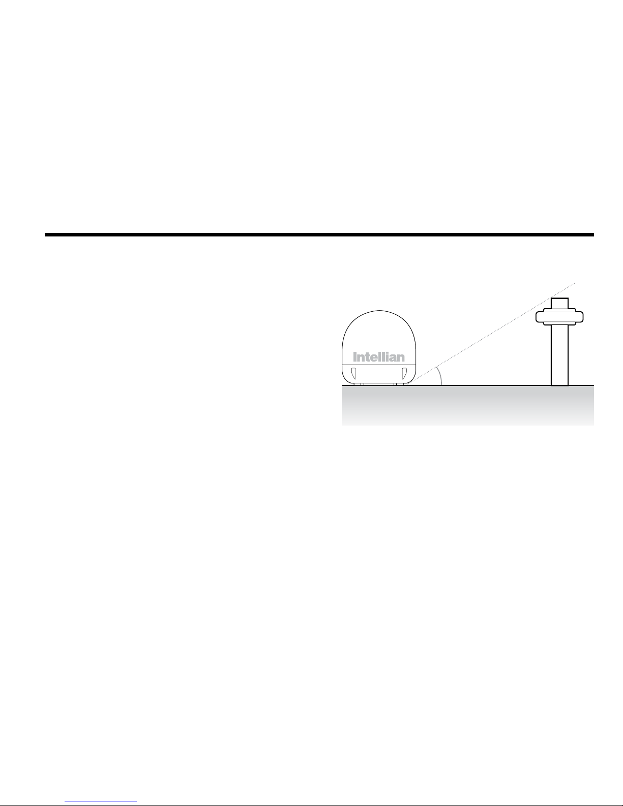
Planning the Installation
Selection of Antenna Installation Site
Install the antenna in accordance with the following procedures to
insure maximum performance.
The antenna should be installed in a place where there is all round clear
view of the horizon. Please be sure there are no obstacles within 15°
above the antenna. Any obstacles can prevent the antenna from tracking
the satellite signal (Refer to the drawing on the right).
Do not install the antenna near the radar especially on the same plane.
Its energy levels may overload the antenna front-end circuits. It is
recommended to position the antenna at least 4 feet (1.2m) above or
below the level of the radar and minimum of 15 feet (4.6m) away from
the high power short wave radars.
The mounting platform should be rigid and not subjected to excessive
vibration. The movement of the antenna can be minimized by installing
at the center of the vessel. For optimal performance of the antenna, it
is not recommended to install at any corner of the vessel, where the
movement of the vessel is the greatest. Install the bottom of the antenna
parallel to the surface of the sea and x tightly to the structure of the
vessel.
When setting the antenna down, be careful not to damage the RF
connector. Striking the connectors on the bottom directly will damage
the connector.
Figure 07 : Elevation Limit of Obstacles
15°
Antenna Unit Obstacle

12
Intellian Satellite TV Antenna Systems
Extending the Cables
The cables that have been supplied with your Intellian system should be
of adequate length to complete the installation on most boats.
Power Cable
This cable supplied at a length of 10m.
Note: Exceeding the indicated cable lengths will result in reduced
performance of your system.
Cables
Before installing the system cables, consider the following points.
•Allcablesneedtobewellclampedandprotectedfromphysical
damage and exposure to heat and humidity.
•Cableswithseverebendsarenotallowed.
•Whereacablepassesthroughanexposedbulkheadordeckhead,
a watertight grommet or swan neck tube should be used.
Power Requirements
You need to follow the power requirements to avoid damage the system.
Intellian i6/i6P/i6PE has been designed to work on a boat’s power
supply rated at 12V / 24 V DC (acceptable range: 9~30 V DC).
If your IRD(s) and television(s) require a 110V/240V AC power supply,
you will need to install a suitable DC to AC converter to operate the
unit(s) from your boat’s DC power supply.
RF Cable
This cable is supplied at a length of 15m. If a longer length is required you
should replace this cable with an extended RG6 RF cable supplied by Intellian
Technologies or equivalent.
13
Installation and Mounting of Antenna
The method of installation and mounting of the antenna may vary due
to vessel design but the following procedures are applicable in most
situations, and will result in a secure and effective installation.
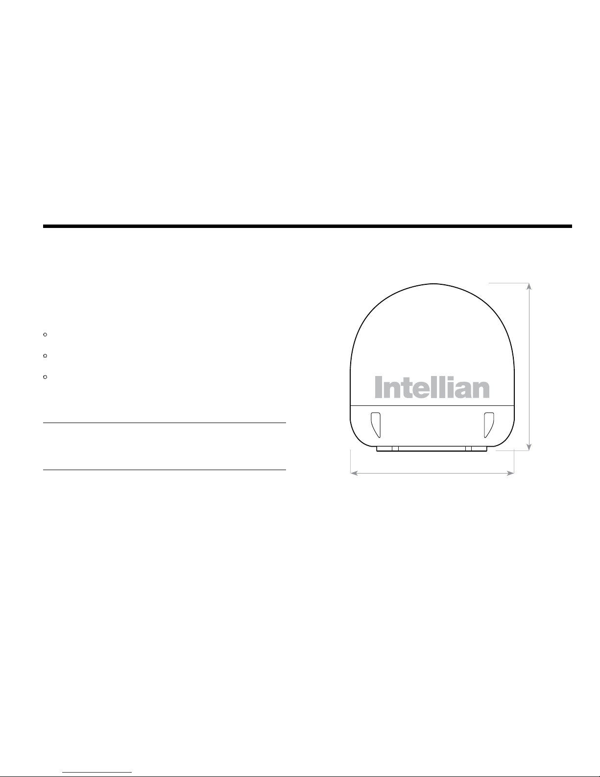
Conrmation of Size Prior to Installation
• Conrm the height and diameter of the bottom surface of
the antenna before installing.
• The space must be sufcient for installing the antenna unit
considering the height and diameter of the antenna.
• The height and the diameter of the bottom surface of the antenna are
as shown in the following drawing. If possible, install the antenna
using a power tower.
Note: Before installing the antenna open the radome and remove the
shipping constraints from the antenna interior. Reinstall the radome
before operating the system. The system will not perform properly if the
radome is open.
Figure 08: Radome Dimension of i6/i6P
Ø70 cm (27.5”)
72 cm (28.3”)
14
Intellian Satellite TV Antenna Systems
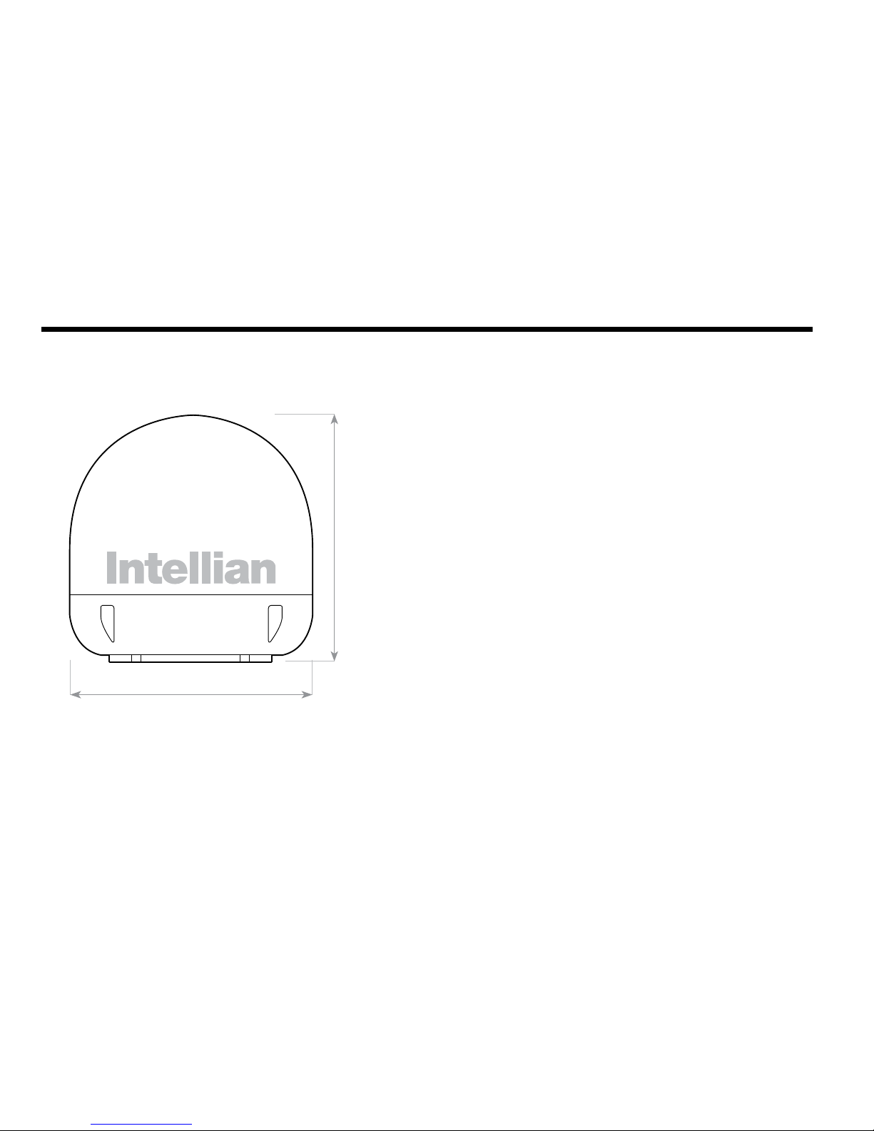
Figure 09 : Radome Dimension of i6PE
Ø70 cm (27.5”)
75.4 cm (29.7”)

15
Mark of the Antenna Mounting Position
Referring to the mounting template, mark where antenna will be
mounted onboard (it must be a at surface) or on a separate power
tower by drawing a square of 30.4 cm (12”)
Note: If a power tower is not suitable to mount the antenna, separate
cable shock and waterproong measures must be taken to protect the
RF connector from being exposed to the sea water and external shocks.
An exposed cable may cause electric shock and cause serious damage
to the equipment.
Figure 10 : Mounting Hole Position of I6/I6P/I6PE
30.4 cm (12”)
30.4 cm (12”)
16
Intellian Satellite TV Antenna Systems
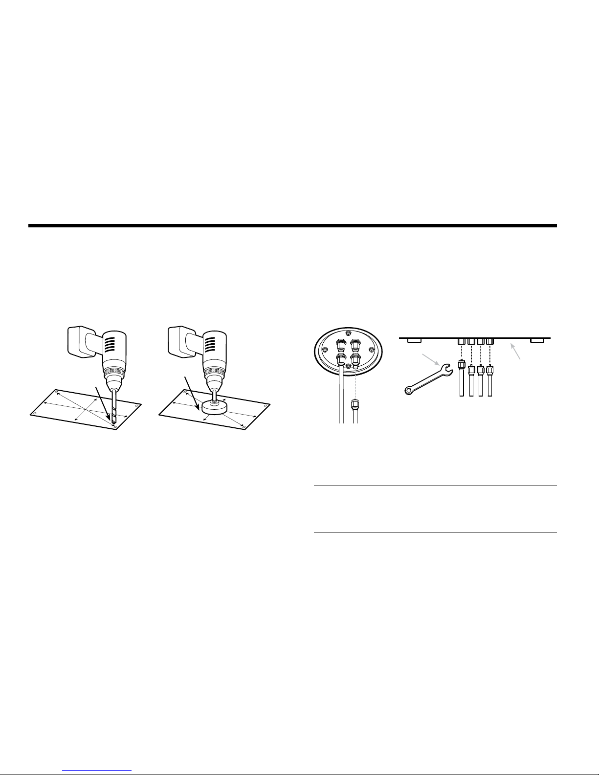
Connection of the Cable
Remove the rubber cap from RF connector. Connect the RF cable to the
RF connector under the base plate through the access hole using an
11mm spanner. Be careful not to over tighten, as you may damage the
connector.
Note: Do not use excessive force when using the spanner, this will
damage the threads. Be careful that the connectors do not contact the
mounting surface of the antenna, this may cause a critical malfunction
and serious damage to the equipment.
Securing Holes for Bolts and Cable Ways
Make 4 bolt holes of 10mm diameter, one at each corner of a rectangle
drawn as below, and make a circular hole of 80mm diameter at the
center of the rectangle through which the cable will run.
Ø80mm
Hole Saw
Ø 10mm
Drill
Figure 11 : Drilling Instruction Figure 12 : Connectors on Bottom of Antenna
Antenna Unit
RF Cables
11mm
Spanner

17
Mounting the Antenna
Attach the antenna by using the hex head bolts (M8X50L), M8 spring
washers, and M8 at washers supplied.
Figure 13 : Mounting the Antenna
Installing the ACU
5.4 cm (2.1”)
5.5 cm (2.2”)
22.8 cm (9”)
17.8 cm (7”)
21.7 cm (8.5”)
18.5 cm (7.3”)
Figure 14 : Dimension of ACU
ACU Dimensions
Radome Base
Deck
M8 Flat Washer
M8 Spring Washer
M8 Hex. Bolt
13mm Spanner
The ACU should be installed below deck, in a location that is :
• Dry, cool, and ventilated.
• Easy accessible from your main TV viewing area.

18
Intellian Satellite TV Antenna Systems
Installing the ACU
1. The ACU should be installed using the two supplied mounting
brackets which allow for a top or bottom mounting conguration.
2. Using the self tapping screws supplied, attach the mounting brackets
to the sides of the ACU.
3. Place the ACU in the location where it is going to be installed.
4. Connect the cables to the rear of the ACU.
5. Using a pencil to mark the 4 hole positions (2 each side), and use the
appropriate drill bit to drill them.
Figure 15 : Installation of ACU
19
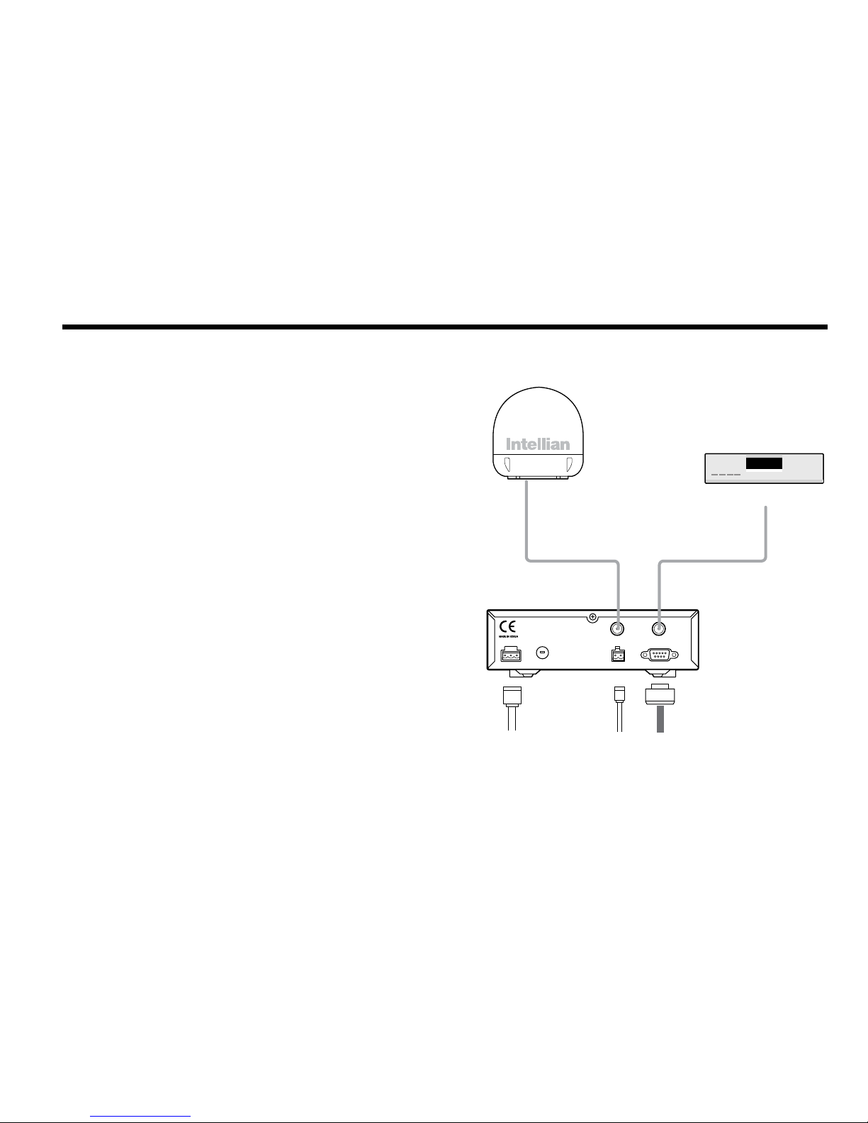
Figure 16 : Single Receiver Connection
Connecting the System Cables
After installation and xation of the antenna, connect the ACU to the
antenna. Refer the drawing below to connect cables.
Single Receiver Connection
• Connect the RF Cable (15m) from the RF 1 connector on the
antenna to the ANT. RF1 connector on the rear of ACU.
• Connect the ACU-IRD Cable (3m) from the RECEIVER connector
on the rear of the ACU to RF on the IRD.
• Connect the power cable (10m) from DC power connector on the
rear of ACU to a power source at 12V / 24V DC.
• Press the POWER ON switch in front of the ACU to start the
operation of the antenna system.
ACU
RF Cable
RF 1
Antenna Receiver
ACU IRD Cable
DC Power Cable NMEA GPS PC Cable
IRD (Not supplied)
NMEA
ANT RF1 RECEIVER
FUSEDC 9 - 30 V PC INTERFACE
FG - +
+ -

20
Intellian Satellite TV Antenna Systems
Figure 17 : Dual Receiver Connection
Dual Receiver Connection
You can connect two IRDs for your antenna as shown in the following
diagram. However, only one of the IRDs can be congured as a two
satellite receiver.
The other IRD needs to be congured as a single satellite receiver.
The two satellite receiver determines which satellite is tracked, while
the other receiver can watch any channel which is available from the
tracked satellite.
As in the single IRD option the RF cables from the antenna base plate
should be connected to ‘LNB’, ‘ANT’, or ‘Satellite In’ on the rear panel of
IRD.
ACU
RF Cable
RF 1 RF 2
Antenna Receiver
ACU IRD Cable
DC Power Cable NMEA GPS PC Cable
NMEA
ANT RF1 RECEIVER
FUSEDC 9 - 30 V PC INTERFACE
FG - +
+ -
IRD 2 (Not supplied)
IRD 1 (Not supplied)
Other manuals for i6
1
This manual suits for next models
2
Table of contents
Other Intellian TV Antenna manuals


