Intellian i2 User manual

7
The components of the Intellian i2 have been designed to be modular so
that it is suitable for simple installation on all types of vessels.
System Components
Antenna Unit
The antenna of Intellian i2 is comprised with the following components
for optimum search and reception of the satellite signal.
• Mechanical Unit – manipulates the antenna to receive an optimal
satellite signal regardless of the movement of the vessel.
• Control Unit – controls mechanical operation of the antenna.
• RF Unit – transmits an optimum satellite signal to the receiver.
• Radome – protects the antenna from severe marine environmenta
Installation
Figure 02 : Radome
8
Intellian Satellite TV Antenna Systems
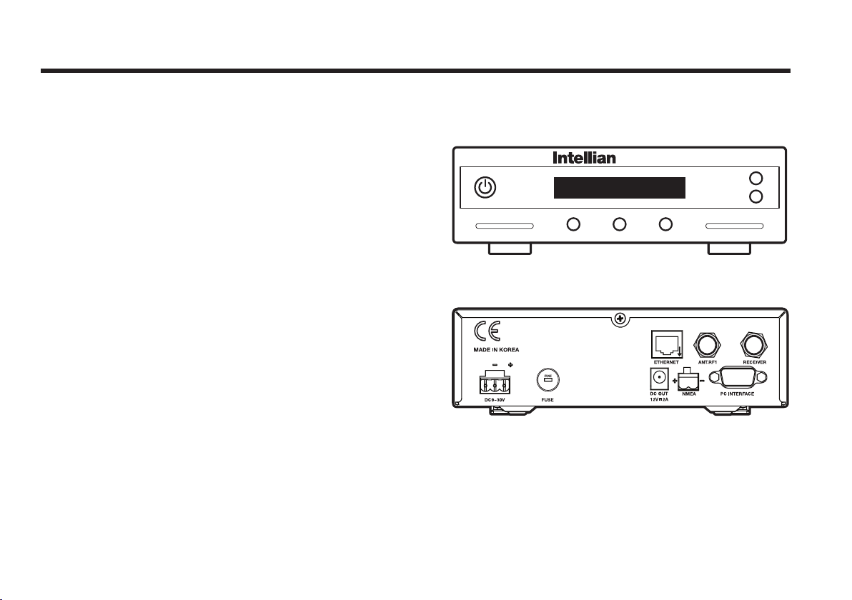
Antenna Control Unit (ACU)
The Antenna Control Unit (ACU) provides the power to the antenna
and controls various settings of the antenna. The digital VFD (Vacuum
Fluorescent Display) allows for easy operation of the ACU, even in the
dark.
The functions of the ACU are as follows:
• Provides power to the antenna unit
• Monitors the antenna status
• Changes the target satellite
• Set up the user environment
• Set the current GPS information
• Set satellite information
• Perform self-diagnosis of the antenna
• Set up the interface with a PC
Figure 03 : Front & Rear of ACU
Front
Rear
Antenna Control Unit

9
Hex.Bolt
5
Flat Washer
5
Spring Washer
5
Hex. Nut
5
Item
Qty
Item
Qty
Size
Self-Tapping Screw
5
(M4 X 16L)
Machine Screw
5
(M3 X 8L)
Antenna
ACU
Installation Kit
Contains the items required for securing the antenna unit and ACU to the
vessel.
Other Components
No Components Size Qty
1 ACU Bracket - 2
2 RG6(Antenna – ACU RF Cable) 15m 1
3 RG6(ACU – IRD Cable) 3m 1
4 Power Cable 10m 1
5 PC Serial Cable 1.8m 1
6 NMEA Connector 1.5m 1
7 Power Connector AK950-2 1
8
Hex Bolt
M6x35L 5
M6x50L 5
Tapping Screw ø4x16L 5
ø3x8L 5
Flat Washer M6 10
Spring Washer M6 5
Nut M6 5
9 Aptus CD - 1
10 User Manual - 1
11 Mounting Template 1
12 Quick Installation Guide - 1
Figure 05 : List of the Supplied Parts
Figure 04 : Installation Bolt Kit

10
Intellian Satellite TV Antenna Systems
Tools Required for Installation
Figure 06 : Required Tools for Installation
Power Drill 11 mm Spanner
Cross-Head
Screwdriver 10 mm Spanner
8 mm Drill Bit
Ø50 mm
Hole Saw
Pencil
Power Drill 11 mm Spanner
Cross-Head
Screwdriver 10 mm Spanner
8 mm Drill Bit
Ø50 mm
Hole Saw
Pencil
11
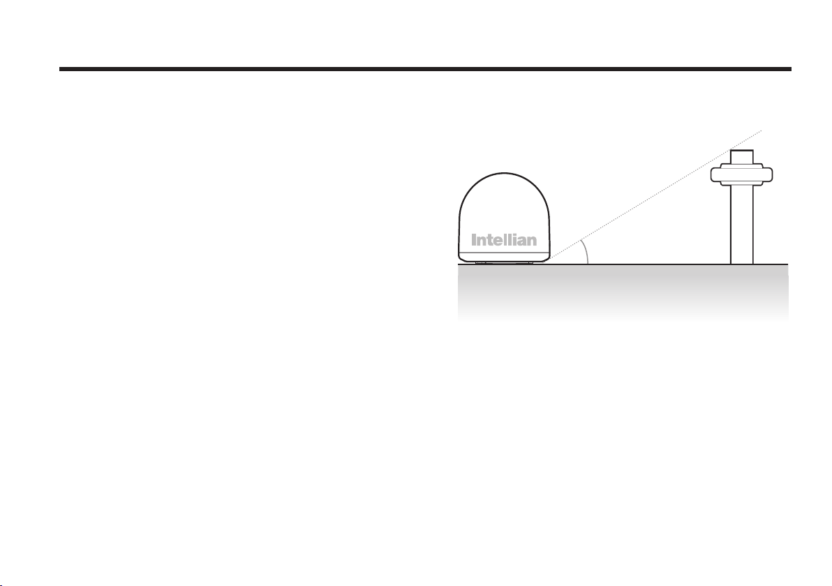
15°
Planning the Installation
Selection of Installation Site
Install the antenna in accordance with the following procedures to
ensure maximum performance of the antenna.
The antenna should be installed in a place where it has an all-round
clear view of the horizon. Please be sure there are no obstacles within
15 degrees above the antenna. Any obstacles can prevent the antenna
from tracking the satellite’s signal (Refer to the drawing on the right).
Do not install the antenna nearby the radar, especially if their on the
same plane, as their energy levels may overload the antenna’s front-end
circuits. It is recommended to position the antenna at least 4 feet (1.2m)
above or below the level of the radar and a minimum of 15 feet (4.6m)
away from any high power short wave radars.
The mounting platform should be rigid enough and not subjected to
excessive vibration. The movement of the antenna can be minimized by
installing it at the center of the vessel. For optimal performance of the
antenna, it is not recommended to install it at any corner of the vessel,
where the movement of the vessel is the greatest. Install the bottom
of the antenna parallel to the surface of the sea and x it tightly to the
structure of the vessel.
When setting the antenna down, be careful not to damage the RF
connector. Striking the connectors on the bottom directly will damage
the connector.
Figure 07 : Elevation Limit of Obstacles
Antenna unit Obstacle

12
Intellian Satellite TV Antenna Systems
Cables
Before installing the system’s cables, consider the following points.
• All cables need to be well clamped and protected from physical
damage and exposure to heat and humidity.
• A cable with an acute bend is not allowed.
• Where a cable passes through an exposed bulkhead or deckhead, a
watertight gland or swan neck tube should be used.
Power Requirements
You need to follow the power requirements to avoid damaging the
system.
• Intellian i2 has been designed to work on a boat’s power supply rated
at 12V / 24V DC (acceptable range: 9~30 V DC).
• If your IRD(s) and television(s) require a 110V/240V AC power supply,
you will need to install a suitable DC to AC converter to operate the
unit(s) from your boat’s DC power supply.
Extending the cables
The cables that have been supplied with your Intellian system should be
of adequate length to complete the installation on most boats.
Power Cable
This cable is supplied at a length of 10m.
RF Cable
This cable is supplied at a length of 15m. If a longer length is required
you should replace this cable with an extended RF cable supplied by
Intellian Technologies.
Note: Exceeding the indicated cable lengths will result in reduced
performance of your system.

13
Installation and Mounting of the Antenna
The method of installation and mounting of antenna may vary due
to vessel design but the following procedures are applicable in most
situations, and will result in a secure and effective installation.
Conrmation of Size and Installation of Power Tower
• Conrm the height and diameter of the bottom surface of the antenna
before installing it.
• The space must be sufcient for installing the antenna unit
considering the height and diameter of the antenna.
• The height and the diameter of the bottom surface of the antenna are
as shown in the following drawing. If possible, install the antenna
using a power tower.
Note: Before installing the antenna, open the radome and remove the
shipping constraints from the antenna interior. Reinstall the radome
before operating the system. The system will not perform properly if the
radome is open.
Figure 08 : Radome Dimension of i2
Ø37 cm (14.7”)
38.1 cm (15”)
14
Intellian Satellite TV Antenna Systems
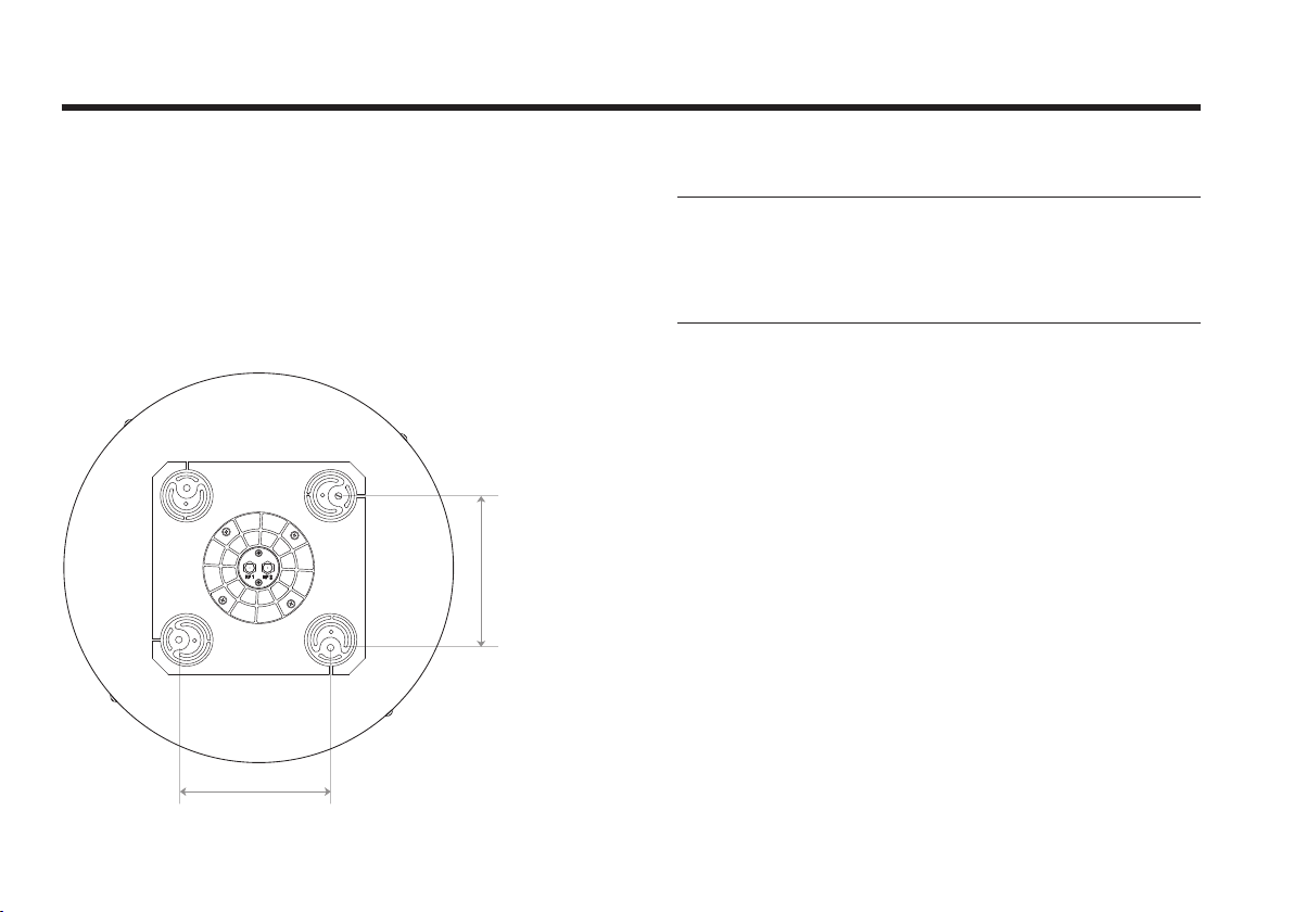
Marking of the Antenna’s Parking Position
Referring to the Mounting template, mark where antenna is to be
mounted onboard the ship (it must be a at surface) or on a separate
power tower by drawing a square of 14.4cm (5.7”)
Figure 09 : Intellian i2
Note: If a power tower is not used to mount the antenna, separate
cable shocks and waterproong measures must be taken to protect the
RF connector from being exposed to sea water and external shocks. An
exposed cable may cause electric shock and cause serious damage to
the equipment.
14.4cm (5.7”)
14.4cm (5.7”)
15
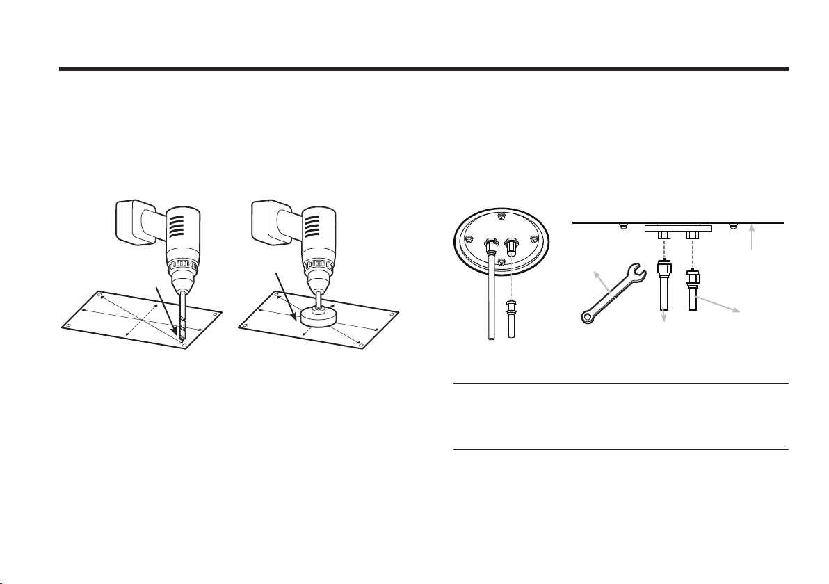
Securing Holes for Bolts and Cable Ways
Make 4 bolt holes of 8mm diameter, one at each corner of a rectangle
drawn as below, and make a circular hole of 50mm diameter at the
center of the rectangle through which the cable will run.
Connection of the Cable
Remove the rubber cap from RF connector. Connect the RF cable to the
RF connector under the base plate through the access hole using an
11mm spanner. Be careful not to over tighten, as you may damage the
connector.
Figure 11 : Connectors on Bottom of Antenna
Note: Do not use excessive force when using the spanner, this will
damage the threads. Be careful that the connectors do not contact the
mounting surface of the antenna, this may cause critical malfunction
and serious damage to the equipment.
Figure 10 : Drilling Instruction
Antenna Unit
RF1 Cable
Optional
11mm
Spanner
Ø50mm
Hole Saw
Ø 8mm
Drill

16
Intellian Satellite TV Antenna Systems
Mounting the Antenna
Fix the antenna to the holes made before as shown in the drawing
below by using the hex head bolts (M6 X 35L), M6 spring washer,
M6 at washer and M6 Nut supplied.
Figure 12 : Mounting the Antenna
ACU Dimensions
Installing the ACU
Figure 13 : Dimension of ACU
Radome Base
Deck
M6 Flat Washer
M6 Spring Washer
M6 Hex. Nut
10mm Spanner
M6 Flat Washer
M6 Hex. Bolt
10mm Spanner
7.5 cm (2.95”)
17.8 cm (7”)
17.8cm (7”) 5.4cm (2.1”)
22.8cm(9”)
18.5cm (7.3”)
21.7cm(8.5”)
Other manuals for i2
2
Table of contents
Other Intellian TV Antenna manuals


