IntelliCam System X2 User manual

1
System X2
DocRef # 04012022
System X2 User Guide Revised 04-01-2022

2
TABLE OF CONTENTS:
Introduction Page 3
Hardware, Controls, and Indicators Page 3
X2 Accessories and X2 Set-Up Page 4
Flashback 4 Setup Page 5
Deployment Settings and Flashback Activation Page 6
Settings for Optimal Battery Life Page 7
Shake Detection and Sensor Use and Programming Page 8
Viewing Pre-Recorded Files and Common APN Numbers Page 9
Technical Specifications Page10
Contact Information Page10

3
INTRODUCTION:
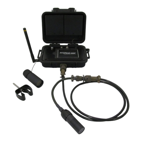
The System X2 is a Dual Camera Surveillance System utilizing the Flashback 4 Digital
Video Recorder and the Flashback 4G GSM/LTE Modem for streaming of the recorded
video. The System X2 is in a weatherproof enclosure. The video recorder will remain in
the “sleep mode” until it receives an alarm signal from any Intellicam sensor. When the X2
receives a sensor alarm signal, it will wake up and start the video recording.
IMPORTANT: All settings are programmed using theFlashback User Interface.
HARDWARE, CONTROLS, AND INDICATORS:
ANT-1 ANTENNA:
This antenna is mounted on the rear of the enclosure. The ANT-1 antenna will receive the
RF alarm signal from any Intellicam sensor.
ANT-C ANTENNA (2):
The two Taoglas antennas are mounted on the rear of the enclosure and are used to
transmit the outgoing GSM/LTE streaming video and or SMS text messages.
POWER INPUT CONNECTOR:
The 4-pin Canon Power Input Connector is mounted on the left side of the enclosure. The
System X2 is designed to accommodate a power supply ranging from 12VDC to 30VDC.
MONITOR CONNECTOR:
The 3-pin Canon Monitor Connector is mounted on the right side of the enclosure. This
connector is used to attach the supplied 5” Monitor for precise aiming of the cameras.
CAMERA 1 CONNECTOR:
The 4-pin Canon Camera 1 Connector is mounted on the front of the enclosure. This
connector is used to attach the AVC-312 Armored Video Cable and Camera 1.
CAMERA 2 CONNECTOR:
The 4-pin Canon Camera 2 Connector is mounted on the front of the enclosure. This
connector is used to attach the AVC-312 Armored Video Cable and Camera 2.

4
SYSTEM X2 ACCESSORIES:
SYSTEM X2 SETUP:
1. Install the three antennas.
2. Attach armored video cables and cameras.
3. Attach video monitor only to assist in aiming cameras at target.
4. Install Static IP SIM card unless you have the correct server settings for a regular
SIM card.
5. Ensure that the 128G SD card is properly installed.
6. Attach power supply or battery pack to System X2.
7. Install batteries into IR-903 Sensor and program ID if necessary.
The X2 is normally used with a “Static IP SIM Card”. You can order Static IP SIM
cards from your “Business Account Representative” at AT&T or Verizon. If you
need help with this, please contact us.
Camera 1 with
AVC-312 Cable
2 ea. ANT-C
GSM-LTE
Antenna
BPK-8D
Battery Pack
5” Monitor
Camera 2 with
AVC-312 Cable
1 ea. ANT-1
Sensor Antenna

5
FLASHBACK 4 SETUP:
Before a cellular connection can be made, the Static IP SIM card, APN, Username, and
Password, and if used, the Server information, have to be entered into the Flashback-4
User Interface. This is accomplished by using the Flashback’s Wi-Fi access point to
access it’s webpage interface. The setup procedure is as follows:
1. Power up the System X2 by connecting the supplied AC power adapter, use of the
Battery Pack during set up is not recommended as you will waste battery power. Once
power is connected, manually trigger the IR-904 sensor, to power up the System X2. Then
wirelessly connect your computer to Flashback DVR via the internal Wi-Fi in your
computer. It may take up 90 seconds before your computer will recognize the Flashback’s
SSID number and you need to make sure your System X2 is within 4 feet of your
computers Wi-Fi signal.
2. Select the Flashback’s (FB-nnnn). Click “Connect” and enter the Flashback’s Wi-Fi
password: fb4wifipw.
3. Once you are connected, open your browser and enter the Flashback’s IP address
172.16.01.1 to open the Flashback Login Webpage. By default, the login user name is
“admin” and the password is “icam1007”.
4. If you are using a Static IP SIM card, enter the “APN” number. Click on the “Network”
Scroll down and click on “4G Modem”. Enter the “APN” number. Once this has been set
up correctly, you can now connect through the Static IP Address for that specific Static IP
SIM card.
5. Recommended Settings while you are setting up and programming the Flashback.
A. Wi-Fi timeout: Set to “Disabled”, this is found under “Network” tab, then scroll
down to the “Wi-Fi” tab.
B. Sleep Mode: Set to “Manual”, this is found under the “System” tab, then scroll
down to “Unit Control”.
C. Date, Time, and Time Zone. Click on the “System” tab, then scroll down to “Date
and Time”. Set the correct Date and Time. Then click on “Paste Current PC Date and
Time”. Make sure you select the correct Time Zone. Click on “Submit” at the bottom
right-hand side of the page to save.

6
HIGHLY RECOMMENDED FLASHBACK DEPLOYMENT SETTINGS:
Before you deploy the System X2, we recommend the following settings to maximize
battery life and performance. How to apply these settings is explained on page 6.
1.Trigger Duration: 2 minutes.
2. Wi-Fi timeout: 15 minutes
3. Sleep Mode: Automatic at 15 minutes
NOTE: If the Flashback does not receive additional sensor triggers, it will go
into “sleep mode”. This is the “window” of time that you get after receiving a
SMS text notification to log into the SIM IP address and look at live video or
pre-recorded video.
FLASHBACK ACTIVATION:
The “record time” can be adjusted via the Flashback “Triggers” menu by setting “Duration”.
Figure 1.
The Flashback User Guide states:
The “Duration” is the minimum video record time after the sensor trigger has ended. This
is useful when handling random length triggers from Passive Infrared Sensors, etc. For
example, if the Duration is set to 2 minutes, the Flashback records video for at least 2
minutes after the final sensor trigger. Re-triggering: If additional sensor triggers are
received during this period, the “Duration” timer is reset to an additional two minutes. The
recorded video will be continuous.

7
Three Key Settings for Optimal Battery Life:
1. Trigger Duration : From the Homepage, click on the “Triggers” tab, scroll
down to “Inputs”. We recommend that both Input 1 and Input 2 be
programmed for 2 minutes. (Fig. 1)
2. Wi -Fi Timeout : From the Homepage, click on “Networks”, scroll down
and click on “ Wi-Fi”, you will see “Wi -Fi Timeout”. We recommend this be
programmed for 15 Minutes . (Fig. 2). Note that the Wi-Fi setting must be less
than or equal to the sleep mode setting.
Fig. 2
3. Sleep Mode – From the Homepage, click on the “System” tab . Scroll down
and click on “Unit Control”, you will find the “Sleep Mode” setting. Program the
setting to “Automatic” and the “Inactivity Period” to 15 minutes (Fig. 3). *The
Sleep Mode value must be greater than or equal to the Wi-Fi Timeout setting,
or the X2 will not go into Sleep Mode. If not, this will cause your batteries to
fail prematurely.
Fig. 3

8
Shake or Tamper Detection
Shake Detection is activated by the amount of mechanical shake
(acceleration), eg physical movement of the System X2 Gateway . Enabling the
“Wakeup” option causes the unit to wake-up from Sleep Mode when the unit is
subjected to the set level of mechanical shake. (Fig. 5) NOTE – This is used to
notify you via SMS text, if someone has tampered with the System X2
gateway. This is not a required setting.
1. Set the Shake Detection, click on the “Triggers” tab. (Fig. 5). Scroll down to
the “Shake” section.
2. “Highlight” the events that you want to occur when a “shake” is detected ,
such as Record, Stream, Snapshot, or SMS.
3. Set the “Shake Level” to 80. The higher the number, the less sensitive the
shake detection becomes.
4. Set the “Duration” to 2 minutes and click on “Submit”.
Fig. 5
SENSOR USE AND PROGRAMMING:
See Intellicam Sensor User Guide for proper set up, programming, and operation of the
various sensor types.

9
VIEWING OF PRE-RECORDED VIDEO FILES:
To view pre-recorded video files located on the “SD Card” tab of the Flashback User
Interface, you must have a “VLC” Media Viewer program installed on your computer,
laptop, and or Cell Phone. You can download a free copy at (https://www.videolan.org).
1. From the Flashback homepage, click on “SD Card” tab on the main menu.
2.Click on the “date” of the recording that you want to view.
3. Select “sd1” or “sd2”. sd1 is for the Camera 1, and sd2 is for the Camera 2.
4. Select which recording you want to view. Depending on the number of triggers you had
for that day will dictate the number of videos for that date. (Fig. 4)
5. Once the video has been downloaded you can click on the video. The VLC Media
viewer should open and allow you to watch the selected video. Fig. 4
VMS – Video Management Systems
When using multiple System X2’s, or other recording devices, such as Pole Cameras. We
recommend the use of a VMS such as Airship. We recommend that you contact your
current VMS supplier to check if your VMS is compatible with the Flashback DVR and 4G
manufactured by Ovation, or by contacting Ovation (www.ovation.co.uk)
Please contact Intellicam for information regarding the how to get Airship or how to use it.
Common Static IP APN Numbers
Network APN Number
AT&T Static IP SIM Card (Business Plan) psmtneofin
Rogers Static IP SIM Card staticip.apn
Verizon Static IP NE01.VZWSTATIC
WE01.VZWSTATIC
SO01.VZWSTATIC
MW01.VZWSTATIC

10
Technical Specifications:
System X2
Enclosure Dimensions 6”L x 6”W x 3.5”H
Enclosure Weight 3.5 Lbs.
Camera Connectors Canon 4-Pin
Video Monitor 5” Color LED Monitor
BPK-8D Battery Pack 8 each “D” cell batteries (12 VDC)
BPK-8D Battery Life 90 days standby or 30 hours streaming video
X2 Gateway Input Power 12-30 VDC
Flashback 4 DVR
Input Power 6 – 30 VDC
Video Inputs 4 channel SD Standard Definition
Video Resolution D1: 720 x 480; 30 fps
SD Memory Card Capacity 2TB; (Comes standard with 128GB SD Card; 60
Hrs.) 1280 video files at 100 mb each (2min)
Flashback 4G Modem
SIM Card (Static IP in most
cases) Mini-SIM (2FF); Standard SIM
Input Power 5 – 12 VDC
Frequencies GSM; LTE; HSPA
CONTACT INFORMATION:
IntelliCam LLC
11138 Air Park Road, Suite H
Ashland, VA 23005
(+1) 804-798-1004
www.intellicam-llc.com

April 1, 2022
System X2 iPhone Quick Setup
Programming iPhones Prior To Field Deployment
1. Download and install VLC Media Player onto your smartphone.
(www.videolan.org)
2. Connect all video cables, cameras, and antenna to the System X2 DVR
enclosure. Connect the video monitor only when aiming the cameras.
(Prolonged connection of the video monitor will greatly reduce battery life).
3. Power up the System X2 by connecting the supplied AC power adapter, (use of
the Battery Pack during set up is not recommended as you will waste battery
power). Once power is connected, manually trigger the IR-904 sensor, to power
up the System X2.
4. Open a web browser on your smartphone and enter the IP address assigned to
your specific System X2. Example: 123.123.123.123 to open the FB-4 User
Interface. If possible, you should “label” this webpage as: “FB4 Webpage”.
Then save it as your “Home Page”.
5. Login to the FB-4 User Interface. Default login is USER: admin /
PASSWORD: icam1007.
6. Once logged onto the Flashback User Interface .Click on Network tab, then
scroll down and click on SMS tab. Check to make sure your smartphone is
programmed into the SMS text list.
7. Next click on the “SD Card” tab. All recorded video and jpeg still shots will be
displayed with date and time stamp.

Viewing Of Video After Deployment:
Overview: Once the System X2 has been deployed at the surveillance site, if anyone
enters that area and “triggers” a sensor, the System X2 will automatically power up,
start recording video, and will send a text to all pre-programmed Users listed in the
Flashback User Interface, notifying them of alarm activity.
IMPORTANT: The System X2 will be powered “on” for only 15 minutes (unless the
suspect remains in that area and “re-triggers” the sensor, which will cause the System
X2 to remain on for additional time until the suspect leaves that area).
The only time window for you to login into the Flashback User Interface is during this
15 minute period after you have received the initial SMS test message.
1. Once you receive the SMS text message, open your smartphone and click on the
FB4 Webpage that was previously loaded onto your phone. (Example IP
Address: 123.123.123.123).
2. Default login is USER: admin / PASSWORD: icam1007).
3. Once on the FB4 Flashback Homepage, click on “SD Card” tab. The recorded
videos will be displayed by date and time. SD1 is for Camera 1 and SD2 is for
Camera 2. With each sensor activation, there will be, both a “video” and a “still
shot jpeg”. Select the desired time and date for the video recording that you wish
to view, and click “Download”.
4. The desired video will be downloaded and you will automatically be redirected to
your phone’s VLC Media Player to view the selected video.

April 1, 2022
System X2 Quick Setup
Programming Guide Prior To Field Deployment
1. Install the Static IP SIM Card into the Flashback 4G Modem. Download and
install VLC Media Player (www.videolan.org) onto your computer or smartphone
or any devices that you would like to play the recorded video.
2. Connect all video cables, cameras, and antenna to the System X2 DVR
enclosure. Connect the video monitor only when aiming the cameras. Prolonged
connection of the video monitor will greatly reduce battery life.
3. Power up the System X2 by connecting the supplied AC power adapter, use of
the Battery Pack during set up is not recommended as you will waste battery
power. Once power is connected, manually trigger the IR-904 sensor, to power
up the System X2. Then wirelessly connect your computer to Flashback DVR via
the internal Wi-Fi in your computer. It may take up 90 seconds before your
computer will recognize the Flashback’s SSID number and you need to make
sure your System X2 is within 4 feet of your computers Wi-Fi signal.
4. If in range, the Flashback 4’s SSID (FB4-nnnn) will be shown on your
computer’s network list. Select the “FB4-nnnn” and click “Connect”. Enter the
default password: fb4wifipw
5. Once connected, open your browser and enter the IP address 172.16.0.1 to open
the FB-4 User Interface. (Default login is USER: admin / PASSWORD:
icam1007).
6. Once logged onto the Flashback User Interface, you can view the factory
“programming” settings. Set the Time, Date, and Time Zone, under “System”.
Then in “Date and Time” click on “Paste Current PC Date and Time”. Make sure
you select the correct Time Zone. Then click “Submit”.
7. The Flashback 4 default trigger duration is set to 2 minutes. (This is the video
record time). Note: Each time a sensor is “re-triggered” the record time will
automatically continue for an additional 2 minutes.
8. The Flashback 4’s Wi-Fi Timeout setting is set to “Disabled”. Sleep Mode is
set to “Manual”. These settings are used for programming only and must be
changed prior to field deployment.

9. From the “Home” screen, select “Periodic” preview mode. This will allow you to
see “live video” via a live connection. From the “Home” screen you can see live
video, start and stop recording, and view input status of the Triggers (Sensors).
10. To set up SMS texting notifications click on Network, then scroll down and click
on SMS menu. You can add up to 16 cell numbers to receive the SMS text
notifications.
11. Once programming is finished, it is the time to program the “Deployment
Settings”.
Highly Recommended Deployment Settings:
1. Set Wi-Fi Timeout to 15 mins. Find this in Network/Wi-Fi Menu.
2. Set Sleep Mode to Automatic at 15 minutes. Find this in System/Unit Control
Menu.
3. Trigger Duration: set to 2 minutes. As stated above this is the initial record
time and resets each time a sensor is re-triggered.
4. Each time you change a setting you must save each setting by clicking on
“Submit” at the bottom right-hand section of each screen.
*Wi-Fi Timeout must always be less than or equal to Sleep Mode or the System X2
will never go into sleep mode which will cause your batteries to fail prematurely.
Table of contents
Other IntelliCam Security System manuals
Popular Security System manuals by other brands
Swann
Swann GuardianEye instruction manual
Philips
Philips In.Sight M100 user manual
Honeywell
Honeywell LYNX TOUCH L5200 Programming guide

FBII
FBII XL-2T Installation and setup guide
Sirena
Sirena SMART-Q2 INSTALLATION AND APPLICATION INSTRUCTIONS

USP/Emergency Caller Products
USP/Emergency Caller Products EC-1 Owner's Manual and Operating Instructions

