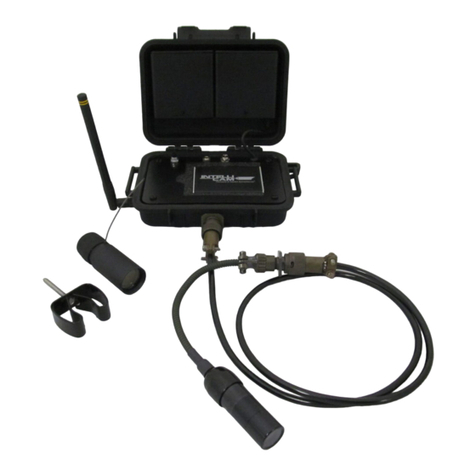
IntelliCam PPK-3 KIT User manual

1
PPK-3 KIT
Perimeter Protection Kit
DocRef# 0100601
PPK-3-Kit User Guide Revised 2016-8-2

2
TABLE OF CONTENTS
Section 1: PPK 3A Receiver Module
A. Introduction Page 3
B. Product View
C. Accessories
I. Set Up Page 4
A. Accessories
B. Power On/Off
II. Alarm and Playback Page 4
A. Alarm
B. Playback
III. PPK-3A Troubleshooting Page 5
A. Low Batteries
B. Limited RF Signal Reception
C. No Audible Beep
Section 2: IR-301 Passive Infrared Sensor
A. Introduction Page 6
B. Product View and Description Page 6
Section 3 Using Passive Infrared Sensors
A. Introduction Page 8
B. Infrared Signal Page 9
C. Infrared Noise Page 9
Section 4 Appendix
A. Technical Specifications Page 10
B. RF Interference Page 11
C. Contact Information Page 11

3
1
PPK-3A
Receiver Module
A. INTRODUCTION:
The PPK-3A is a receiver module that will provide the operator with
notification of a perimeter breach. IMPORTANT: The PPK-3A Receiver
will only receive alarms from the PPK’s IR-301’s sensors and not
with other standard Intellicam sensors.
B. Product View
1. Power Slide Switch
2. SMA Antenna Connection
3. Headphone Jack
4. Playback Button
5. Red and Green LED Lights
C. Standard Accessories
1. SMA Stainless Antenna
2. Earbud Headphones (not pictured)
3. Beeper Module
Beeper
Module
Slide
Switch
Red/Green
LEDs
Playback
Button
SMA
Antenna

4
I. PPK-3A Set Up
A. Accessories
1. Batteries: Remove all 4 screws (2 in each end panel), remove
bottom access panel, and slide cover down. Insert 3 each ‘AAA’
batteries.
2. Internal Dip Switches: Above the battery clips are two DIP
switches to manually turn off the LEDs or the vibrator. When these
DIP switches are in the “off”position, the LEDs and/or the vibrator
will never come on.
3. Antenna: Screw ANT-2 Stainless Antenna onto SMA connector
located on top panel. Other optional antennas are available.
4. Beeper and Earbud Headphones: The PPK-3A will send an
audible tone to the Beeper Module or Earbud Headphones. Plug in
the desired device into the Headphone Jack.
B. Power On/Off
1. Slide the Power Slide Switch on the top panel to the desired
position.
2. Always remember to turn the PPK-3A to the “Off” position after use
to conserve battery life.
II. Alarm and Playback
A. Alarm
1. New Alarm: When a new sensor alarm occurs the PPK-3A will
notify the Operator of the corresponding Sensor ID Number. The
PPK-3 will indicate the Sensor ID Number by one of three methods,
Red LEDs, audible beep, or the covert vibratory mode.
B. Alarm Playback
1. Alarm Playback: To recall and playback the most recent alarm,
press the Playback Button located on the front panel of the PPK-3A.
During playback, the Green LEDs will indicate the Sensor ID
Number. Also, the last beep and vibrate will be longer to indicate
that it is a playback, and not a new alarm.

5
III. PPK-3A Troubleshooting
A. Low Batteries
1. System Reset: When the batteries get critically low, the system
may reset and lose the previously stored Sensor ID Number.
B. Limited RF Signal Reception
1. SMA Antenna, or other antennas, may not be securely attached to
SMA connector.
2. Interference from surroundings such as bushes, trees or walls may
be blocking RF signal to the PPK-3A Receiver. Optional antennas
may increase reception.
C. No Audible Beep
1. The problem may be the Headphone Jack. First check both the
Beeper Module and the Earbud Headphones to ensure that these
devices are working properly. It is not recommended to use any
other Headphones or 3.5 mm accessories with the PPK-3A.

6
2
IR-301
Passive Infrared Sensors
A. Introduction:
The IR-301 Passive Infrared Sensor is capable of accurately detecting the
movement of human and vehicular targets. The IR-301 is packaged in a
rugged aluminum tube with integrated sensor, transmitter, and battery
holder.
The IR-301 is a non-programmable sensor designed for quick deployments
with fixed Sensor ID’s of 1 through 4 and a fixed Sensor Sensitivity of “3”.
The PPK 3 Kit is designed for perimeter protection. The Operator can locate
the four IR-301 sensors with unique Sensor ID’s of 1, 2, 3, and 4 around the
perimeter and record the sensor locations on the site plan. If a Sensor is
triggered, it will send a wireless RF signal to the PPK-3A receiver letting the
Operator know the exact location of the perimeter breach by way of the
unique Sensor ID number.
B. Product View and Description
IR-301 SENSOR
A) BATTERY COMPARTMENT
B) ALARM LED
C) ANTENNA
D) LENS

7
Battery Compartment:
The IR-301’s batteries are self-contained. Slide the rubber boot off the back
of the sensor and replace the batteries with 2 each CR1225 Lithium
Batteries. These should power the IR-301 for approximately 2-3 weeks
depending on the number of sensor activations. When not using the sensor,
you can disconnect the power by slipping a small piece of plastic between
the + lead and the top battery.
Red LED:
The RED LED is an alarm indicator. It only illuminates when an alarm
occurs during the first 10 minutes to aid in the initial set up and will
automatically turn off after 10 minutes for covert reasons.
Antenna:
The flexible stainless ANTENNA allows for the UHF propagation of the RF
signal. The ANTENNA must be oriented in a vertical direction for best RF
propagation and for proper alignment of the infrared beams.
Lens:
The IR-301’s focal length is preset to detect a person at an optimum
distance of 20 feet, although it will work satisfactorily over a range of 5 to
30 feet. Its field of view is about 6 feet wide at a distance of 30 feet. The
LENS is aimed in the direction of your target area.

8
Chapter 3 - Using Passive Infrared Sensors
3
Using Passive
Infrared Sensors
Narrow Beam Passive Infrared sensing offers
many advantages over other sensor types.
A. Introduction:
This technology is the most advanced when used in an outdoor environment.
Its versatility, small size, long range, precise targeting, and target
classifying allow it to be used reliably in many diverse applications.
However, having a fundamental understanding in how to use it is essential in
getting good results.
Since the IR-301 senses thermal movement at an extremely long range, it is
important to have it aimed at a proper background. There are some setups
that cannot be compensated for and will give you false alarms if you aren’t
aware of them. All setups involve maximizing what we call the signal to
noise ratio. The signal corresponds to whatever it is we are interested in
detecting, be it a bird, a human, an automobile, or an airplane, which all
have different sizes, shapes, and travel at different speeds. As far as the IR-
301 is concerned, they will all result in a different signal or infrared signature
when the IR-301 sees them. This will involve placing the sensor at a certain
distance and orientation to the target so that the signal is maximized.
The thing we want to minimize is the noise, or whatever the IR-301 sees
when the target is not there. This is the background such as bushes, trees
or open terrain. Because of the sun’s radiation and the chilling effect of the
wind, the outdoor environment often appears to an infrared sensor as a
moving thermal mass, much like the target we want to measure. Minimizing
this unwanted noise involves aiming the sensor at an appropriate
background. The safest backgrounds are open terrain (open distances up to
100 ft. and beyond) and solid ground.

9
Chapter 6 - Using Passive Infrared Sensors
B. Infrared Signal:
The optimum signal produced by a human is at a distance of 20 feet for the
IR-301, with the person walking at a casual pace (3 ft./sec). This is strictly
a function of the sensor’s optics, which is fixed and determines the devices
beam spread (4 ft. @ 20 ft. for the IR-301). At 20 feet, a person completely
fills the sensing region of each beam causing a maximum signal. Further
away than 20 feet, the person only partially fills the sensing region, thereby
generating a smaller signal. Closer than 20 feet, the person passes through
the beams faster since they are closer together, likewise generating a
smaller signal.
Therefore a person running by the sensor at 10 feet may register the same
as a person walking by at 30 feet, neither being sufficient to trip the sensor.
Automobiles will likewise be difficult to detect when the sensor is mounted
close to the road and they are moving fast. To compensate, you can either
move the sensor back from the road (fifty feet is OK) or you can aim the
sensor using a slight 70 degree angle, which in effect causes the sensor
beam geometry to widen. This will give much better results, especially if the
sensor is aimed upstream, since the target will be detected sooner. Also,
the RF transmission range between sensor and receiver should be kept
short, which will improve the overall reliability.
C. Infrared Noise:
Infrared Noise includes all environmental disturbances that occur when the
sensor is not detecting a target, such as wind chill on stationary objects or
blowing tree leaves on moving objects. Much of these types of disturbance
are filtered out by the side-by-side orientation of the infrared beams. Thus,
heat rising from a blacktop road will hit both beams simultaneously, causing
a cancellation of their signals. However, under certain circumstances, a tree
branch moving back and forth as the wind blows can look like a person doing
the same thing. This can really be a problem if the sensor is aimed at the
solid surface, which is relatively warm due to sunlight, and the cooler leaves
from a branch are blowing in front of the Sensor. A blade of grass located a
few inches from the sensor, blowing in the wind, can also appear as a person
walking, again because of the smaller beam geometry at that distance.
To prevent unwanted false alarms or reduced sensor performance, the
sensor should always be located on a stationary object (large tree trunk),
which will not move when the wind blows (avoid smaller diameter trees).
Any offending grasses or branches should always be pruned away from the
sensor’s field of view. Avoid aiming the sensor at trees with moving
branches, especially at close distances (less than 10 feet).

10
4
Appendix:
A. Technical Specifications
IR-301 Specifications:
Power
2, CR1225 3 volt Lithium
Operating
Temperature
14 F to 122 F (-10 C to +50 C)
Operational
21 days; based upon sensor activations
Sensing Method
Dual Element Pyroelectric Detector
Max. Detection Range
@ 80 deg. Ambient
Human Targets: 30 feet
Vehicles: 60 feet
RF Output Power
1 mw, per FCC Part 15 Rules (FCC ID RVL-
SICSAW916)
Modulation
OOK, 2-4Khz
RF Frequency
916.5 MHz (SAW stabilized)
Field of View
15 degrees
Dimensions
1.0” dia. x 2.8” length
Weight
1.8 oz. (45g)
PPK-3A Receiver/Processor Specifications:
Battery Type
3 each AAA 1.5 VDC Lithium Batteries
Power Supply Current
Normal Operating: 2.5 milliamps
Sleep Mode: 300 micro amps
Operating Temperature
14 F to 122 F (-10 C to +50 C)
Frequency
916.5 MHz (SAW stabilized)
Sensitivity
-98 dbm; (300 ft. range, line-of-sight)
Electronic Output
NPN Transistor (Open Collector, 20ma max)
Dimensions
2.25 width X 4.00” length
Weight
5.5 oz. (156g)
Notifications
LED, Audible, and Covert Vibratory

11
4
Appendix:
RF Interference
B RF Interference:
This device does not cause harmful interference.
This device must accept any interference received, including interference
that may cause undesired operation.
When operating in an urban area, sources of interference can include 900
MHz cordless phones, spread spectrum phones, computers, and other data
transmission devices. Interference caused by these sources is usually of
limited range (100 ft.) due to the fact that the FCC restricts the power
output at this frequency. Although the Receiver/Processor will reject most of
this interference, it is best to locate the interfering source and remove it (if
possible) prior to doing installation, or degraded reliability could result.
WARNING:
This device operates under Part 15 of the FCC Rules. Any modification not
expressly approved by IntelliCam, LLC may void the warranty and the
user’s authority to operate this device!
C. Contact Information:
Intellicam LLC
11138 Air Park Road, Suite H
Ashland, VA 23005
(+1) 804-798-1004
www.intellicam-llc.com
Table of contents
Other IntelliCam Security System manuals
Popular Security System manuals by other brands

Black Widow Security
Black Widow Security BW FM 100 installation manual

Tracon Electric
Tracon Electric WANKUOO Series user manual
Wetelux
Wetelux 83 14 68 instruction manual
Arrowhead Alarm Products
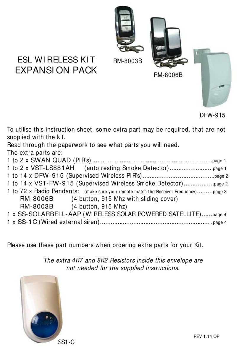
Arrowhead Alarm Products RM-8003B manual

Lindab
Lindab Fire System Pro Commissioning instructions

GE
GE NX-10 user manual
