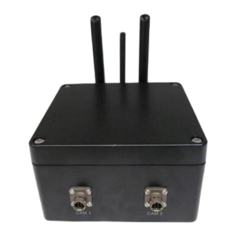
IntelliCam SYSTEM II User manual

1
SYSTEM II
Low Light Surveillance System
DocRef # 0030603
System II User Guide Revised 2019-9-19

2
TABLE OF CONTENTS:
INTRODUCTION Page 3
SYSTEM CONTROLS AND INDICATORS Page 3
Power/Receiver Processor
Programming/Reset Button
Red LED
Antenna
SYSTEM RECEIVER / PROCESSOR Page 4
Receiver / Processor
Video Run Time
SYSTEM QUICK SETUP Page 5
IR-903 SENSOR CONTROLS AND INDICATORS Page 8
Battery Holder
Programming Button
Red LED
Antenna
Lens
SENSOR RANGE TEST MODE Page 9
SENSOR WALK TEST MODE Page 10
SENSOR PROGRAMMING Page 11
Sensor Default Mode
Sensor ID and Sensitivity Programming
Sensor Sensitivity Table
USING PASSIVE IR SENSORS Page 13
Infrared Signal
Infrared Noise
RF INTERFERENCE Page 14
TECHNICAL INFORMATION Page 15
Sensor Specifications
Receiver/Processor Specifications
Power Requirement for DVR, Monitor, etc.
ACCESSORIES Page 16
RIL-1 Remote Infrared Illuminator
LLC Low Light Camera
CONTACT INFORMATION Page 17

3
INTRODUCTION:
The System II is packaged in a weatherproof enclosure containing a 32G Digital Video
Recorder with the integrated RX-930 Receiver Processor and AA Battery Pack. The System II is
the smallest, lightest, and most advanced video surveillance system on the market today. This
small form factor is designed for ease of concealment
SYSTEM II CONTROLS AND INDICATORS:
The Digital System II includes:
Micro 32G Digital Video Recorder with Remote Control
8 each AA Battery Pack
LLC-12 Low Light Black & White Camera
Non-armored video cable with Canon connectors
IR-903 Passive Infrared Sensor with TC-1 Tree Clip
2 each antenna
3.5” LCD Monitor
Phone jack for Video
Monitor input
Program/reset button
and LED
IR port for using
remote control of
DVR
SD card slot
IR903 Sensor
Tree clip
Camera
DVR power
Video out
Video in
3.5mm jack for Video
Monitor power
Antenna

4
Power/Receiver Processor
The Receiver/Processor Module accepts 12-Volt DC power from the integrated “AA” battery pack.
The Receiver pulls approximately 2.6 ma while it is “awake” and 5ua in the “sleep” mode. This
translates to about 14 days of operation (awake continuously) using alkaline batteries and about
1 month using Lithium batteries.
Programming/Reset Button
This button resets the Receiver Processor (clears the memory) and allows for limited
programming (video runtime variable). To clear the memory and reset the processor, press and
hold the Program/Reset Button until the Red LED comes on, then release it. The Program/Reset
Button can also turn “off” the DVR after an alarm trigger.
Red LED
The Red LED is used for programming and as an alarm indicator. It is also used to detect the
presence of other interfering devices operating at 916.5 MHz when it flickers. It only illuminates
for approximately 10 minutes and automatically turns off thereafter for covert reasons.
Antenna
The Receiver’s antenna is connected to the SMA receptacle. The antenna should be located
several inches from leaves, vines, etc., for best reception. RF reception is at 916.5 MHz (868.35
European) and is line-of-sight for best range.
SYSTEM RECEIVER PROCESSOR:
The Receiver/Processor is designed to receive signals from sensors, process the information,
and then controls the video recorder. Whenever an alarm occurs, the sensor sends a packet of
data or alarm record that characterizes the object that it detected. Some or all of the data can be
used to qualify the alarm before a decision is made to activate the video recorder and camera.
Alternately, the most important variable, the Receiver’s Video Runtime Variable, can be manually
programmed with the Program/Reset Button.

5
SYSTEM II QUICK SETUP:
1. Setup the Sensor (refer to section on Range Test, Walk Test).
2. Open System II Pelican Case. Remove battery pack insulator. (Replace 8 “AA” battery cells if
necessary.)
3. Prepare Digital Recorder.
a. Insert SD card into slot on left side of DVR (32G max)
b. Connect the Video monitor
c. Set the correct Date and Time on the DVR under MENU using the DVR’s
Remote Control.
4. Setting Date and Time.
a. Turn “on” the DVR by tapping the Program Reset Button. Gently lift the front of
the DVR at a slight angle to expose the DVR front panel. (See picture below.)
Using the DVR’s Remote Control included with your system, aim the Remote
Control at the IR port on left corner of the DVR and push Menu.
1. Gently lift the front of the DVR to expose IR port.
2. Push ‘Menu’ on Remote Control then scroll down to “System Setting” and push OK.

6
3. Scroll down to “Time” and push OK.
4. Enter the correct Date and Time and push OK
5. Scroll down to “Timestamp” and push “OK”, ensure ‘Timestamp’ is set to “Yes”. Then “Exit’.
5. Attach the camera to the small Canon military connector on the front of the system
case. Attach camera to Tree Mount Clip. Aim the camera at the target area. Camouflage
the camera, being careful of lens glare. Note: The camera has an automatic iris for light
level compensation and is pre-focused. The entire unit is water-resistant, but not
submersible.
6. The System II comes with two antennas. Select the desired antenna and attach to the
system’s SMA receptacle. If using the optional ANT-4 dipole antenna, tie off the antenna
to a small bush or hang it from a tree. Camouflage the antenna wire. For best results, try
to keep leaves and foliage away from the antenna. It makes no difference how the
antenna is oriented, but for best results, keep it in a vertical plane.

7
7. Runtime Programming: Open the System II top cover, remove the two battery pack
covers, and remove the battery tab to activate the Video Controller’s “AA” battery pack (or
insert “AA” batteries). The factory “default runtime” is one minute. To program a specific
runtime, press and hold the Program/Reset Button until the Red LED comes “on” and
immediately enter the video runtime variable by tapping the button once for each 10
seconds of runtime. After entering the desired runtime, the Red LED will “flash” to confirm
the number of “button taps” for the entered runtime. Programming is now complete.
Additional “pressing” of the Program Reset button will only turn “on” or “off” the DVR.
To view the camera, you will need to connect the 3.5” Video Monitor supplied with the
system. Connect the monitor to the power and video connectors on the top cover plate.
Press the Program Reset button to power “on” the DVR. You should now have a picture
on the Video Monitor. Aim the camera at the target while viewing the picture on the
monitor display screen. Turn the DVR “off” by tapping the Receiver Processor’s
Program/Reset Button. The DVR and camera can be tested in this mode prior to field
deployment.
8. Setup the Sensor and Walk Test the Sensor so that an alarm occurs. After the 8
second DVR “boot up” the DVR should turn “on” in the Record Mode simultaneous to the
Receiver Processor’s Red LED illuminating (indicating valid alarm). Reset (turn off) the
Video by pushing the Program/Reset Button.
Note: If the sensor trips but fails to activate the Receiver/Video Recorder, this may mean
that you are out of RF range. Check by resetting the Sensor to the Range Test Mode and
tripping it. The Receiver Processor’s Red LED should flash in concert with the Sensor’s
Red LED, indicating solid RF reception. Absence of the Red LED flashing, or flashing
erratically, means that you are out of RF range. The maximum range depends on terrain,
obstructions, and other factors.
9. Disconnect the Video Monitor, turn “off” the DVR, and shut the Pelican case lid.
10. When returning to the site to check the video, always trip the sensor so that you have
established an ending date for the period of surveillance. This may be useful for
troubleshooting the system if problems occur. Open the Pelican Case and turn on the
DVR using the Program/Reset Button. You can review the evidence on the SD card by
connecting the video monitor and using the supplied Remote Control. Enter the Main
Menu and scroll down to Playback.

8
IR-903 SENSOR CONTROLS AND INDICATORS
IR-903 Passive Infrared Sensor
A) BATTERY COMPARTMENT
B) PROGRAMMING BUTTON
C) BLUE PROGRAMMING & ALARM LED
D) ANTENNA
E) LENS
Battery Compartment:
The IR-903’s batteries are self-contained. Slide the rubber boot off the back of the sensor and
replace the batteries with 2 CR1225 Lithium Batteries. These should power the IR-903 for
approximately 60 days depending on the number of sensor activations. When not using the
sensor, you can disconnect the power by slipping a small piece of plastic between the + lead and
the top battery.
Programming Button:
The IR-903 uses a PROGRAMMING BUTTON for programming and control. The
PROGRAMMING BUTTON is slightly below the BLUE LED. Programming is accomplished by
quickly pushing or “tapping” the PROGRAMMING BUTTON.
Blue LED:
The BLUE LED is used for programming and as an alarm indicator. It only illuminates when an
alarm occurs during the Range Test/Walk Test period (2 minutes) and automatically turn off after
10 minutes for covert reasons.

9
Antenna:
The flexible stainless ANTENNA allows for the UHF propagation of the RF signal. The
ANTENNA must be oriented in a vertical direction for best RF propagation and for proper
alignment of the infrared beams.
Lens:
The IR-903’s focal length is preset to detect a person at an optimum distance of 30 feet, although
it will work satisfactorily over a range of 5 to 50 feet. Its field of view is about 10 feet wide at a
distance of 50 feet. The LENS is aimed in the direction of your target area.
The IR-900B is a long-range version of the IR-903 and utilizes an external battery pack. Its focal
length is preset to detect a person at an optimum distance of 100 feet, although it will work
satisfactorily over a range from 20 to 200 feet. The field of view at 100 feet is about 5 feet wide,
allowing for very precise control over the sensing region.
SENSOR RANGE TEST MODE:
Range Test Mode:
Sensor Range Test Mode is used to verify the maximum RF transmission distance from the IR-
903 Sensor to the Receiver/Processor. The IR-903 Sensor range test may be monitored by
several methods. One method is to simply program the frequency (916.5 MHz, AM mode) of the
IR-903 Sensor into a scanner. Another method would be to use another Intellicam device with a
Receiver/Processor such as the WTM-3A Walk Test Module. The WTM-3A is an optional device
and must be purchased separately, but has the advantage of mobility and small size. The other
option is to use any Intellicam System II receiver, the unit can either be carried while range
testing or can be placed near the target area on the ground, in which case the operator can
observe the RED LED on the receiver processor module. There is nothing the operator has to do
to the Receiver/Processor except apply power from the battery pack.
Screw the TC-1 Sensor Tree Clip into the tree, about 3 to 4 feet above the ground level and
install the sensor. It is best to locate the Receiver on the same side of the tree as the Sensor so
that the tree will not block the RF signal. The best range is achieved with line-of-sight conditions,
that is, with no obstructions coming between the Sensor and Receiver/Processor. Position the
IR-903 Sensor in the tree mount with the antenna vertical. Aim the Sensor at the target area. To
activate the IR-903, remove the plastic insulator from the batteries. As soon as power is applied,
the BLUE LED should come on and go off. After about a 30 second stabilization period, the
Sensor will automatically go into the Range Test mode.
Trip the Sensor by slowly waving your hand in front of the lens. When the Sensor trips, it will start
transmitting at 1 second intervals and with the Sensor BLUE LED flashing. Walk away from the
Sensor with the Receiver/Processor in your hand. The maximum range will be found when the
RED LED on the Receiver/Processor stops flashing or becomes erratic. You should cut this
distance in half for a more reliable setup, since RF/UHF frequencies cannot be predicted with any
great certainty due to absorption and reflections from nearby objects. The Range Test should
involve hanging the Receiver/Processor antenna in a suitable bush or tree, with appropriate
camouflage, and standing back from it. If the RED LED flashes on the Receiver/Processor
become erratic then you know that you are exceeding the maximum RF transmission distance.

10
Generally, if distances are kept below 100 feet, there should be little problem with the setup.
Factors that degrade the RF performance will be thick vegetation, buildings, or metal objects. For
longer range applications, repeaters are available that will send the alarm signal up to several
miles if so desired.
Range Test can be repeated if desired by pressing and holding the sensor PROGRAMMING
BUTTON until the BLUE LED comes on. After the BLUE LED comes on, immediately release
the PROGRAMMING BUTTON. Wait for several seconds and trip the Sensor with your hand.
When the Sensor trips, it will start transmitting at one second intervals with the Sensor BLUE
LED flashing. Range Test will normally last for about 1 to 2 minutes. Range Test can be aborted
at any time by momentarily pushing the PROGRAMMING BUTTON. The Sensor will then go into
the active Alarm Mode.
SENSOR WALK TEST MODE:
Sensor Walk Test Mode is used to verify the maximum detection distance that the IR-903 Sensor
will detect either a human or vehicular target.
First, initiate the Range Test Mode. When the Sensor trips (indicated by flashing BLUE LED),
abort the Range Test Mode by quickly “pushing” the PROGRAMMING BUTTON. The BLUE
LED will stop flashing. The Sensor is now armed and in its Default Mode with a Sensor ID 3 and
the Sensitivity in Full Auto Chameleon and ready for the Walk Test. (Alternately, you can
program a different Sensor ID and a different Sensitivity prior to Walk Test. See Sensor
Programming).
With the Sensor aimed at the target area, walk back and forth in the area where the sensor is
aimed. This motion will trigger the Sensor and the sensor’s BLUE LED will flash and an alarm
will be transmitted to the System II’s Receiver/Processor.
The Receiver’s RED LED will flash when it receives the sensor’s alarm. (The BLUE LED from
the Sensor and RED LED Receiver/Processor will illuminate only for the first 10 minutes. After
10 minutes, it will no longer illuminate for covert reasons. To reactivate the BLUE LED on the
sensor, simply remove and reinstall the CR-1225 batteries. To reactivate the RED LED on the
System II receiver, press the Receiver’s PROGRAMMING BUTTON.)
The Sensor takes 4-6 seconds to reset after an alarm is transmitted, so pause briefly before
attempting to re-enter the Sensor’s field-of-view. After you have located the Sensor’s beams with
the Walk Test method, walk at a slower pace to ensure that detection will be reliable.

11
SENSOR PROGRAMMING:
IR-903 Passive Infrared Sensors:
The IR-903 Passive Infrared Sensors can be programmed with a different Sensor ID and
Sensitivity Levels, or it can be used in the Default Mode, where the Sensor ID 3 and the
Sensitivity is set to Full Auto Chameleon. Programming Sensor ID’s is helpful when deploying
multiple sensors in the same area. The Default Mode is the simplest to use, requires no
programming input, and comes up automatically after power is applied and the Range Test is
completed. The Default Full Auto Chameleon Sensitivity is highly recommended for most
applications, particularly when the ambient temperature changes considerably during the day, in
which case the IR-903 will automatically adjust the sensitivity for the best Signal (target) to Noise
(background) ratio.
If programming is desired, enter the Sensor ID followed by the Sensitivity. The Sensor ID tells
the Receiver/Processor which Sensor went into alarm. The Sensitivity determines how far away
the Sensor will detect a target.
Optional Sensor Programming:
When power is applied the IR-903 enters the programming menu, the BLUE LED will illuminate
for 5 seconds. The user may press the PROGRAMMING BUTTON to program a Sensor ID and
Max Sensitivity. Each button press will reset the menu timeout to 3 seconds. After each
programming menu, the IR-903 will play back the entered Sensor ID and Max Sensitivity. If the
user does not program a Sensor ID or Max Sensitivity, the IR-903 will play back the default
Sensor ID of 3, or the default Max Sensitivity of 5.
Sensor ID Menu:
The first menu is the Sensor ID menu. When power is first applied the IR-903 enters the Sensor
ID menu, the BLUE LED will illuminate for 5 seconds. The user can program a Sensor ID from 1
to 5 by pressing the PROGRAMMING BUTTON 1 to 5 times. After the Sensor ID menu times
out, the IR-903 will play back the Sensor ID. If the user does not program a Sensor ID, the IR-
903 will play back the default Sensor ID of 3. The Sensor ID is transmitted when the IR-903
detects a target. The Sensor ID is used by some receivers to perform different functions.
Max Sensitivity Menu:
The second menu is the Max Sensitivity menu. After the confirmation of the Sensor ID, the BLUE
LED will illuminate for 5 seconds, at which time the user can program a Max Sensitivity from 1 to
5 by pressing the PROGRAMMING BUTTON 1 to 5 times. After the Max Sensitivity menu times
out, the IR-903 will play back the Max Sensitivity. If the user does not program a Max Sensitivity,
the IR-903 will play back the default Max Sensitivity of 5. The Max Sensitivity determines how far
away the IR-903 can detect a target. Setting a Max Sensitivity less than 5 may be necessary if
there is environmental noise in the IR-903 field of view, and the user wished to detect targets
closer than the environmental noise. Regardless of the Max Sensitivity, the IR-903 will still use
Chameleon™ Environmental Adaptive Technology to lower the sensitivity if the environment
becomes unstable. When the environment is stable again, the IR-903 will raise the sensitivity
back up to the Max Sensitivity. (See Page 14 for more information on Detection Distances.)

12
IR-903 Sensitivity Table
Press Button Value
Maximum Sensitivity
Description
No entry
Full Auto Chameleon
Mode
Human Target to 50 feet.
Vehicles to 150 feet.
The Sensitivity automatically varies from maximum range to
minimum range depending on how thermally stable the
environment is acting. If the environment is quiet, such as during
nighttime or on a cloudy day, the Sensitivity will be highest (value
5). If the environment is noisy, such as during a thunderstorm, the
Sensitivity will be at its lowest (value 1).
1
Human Target @ 10 feet
Sensor will detect a person up to 10 feet and vehicles to 20 feet.
2
Human Target @ 20 feet
Sensor will detect a person up to 20 feet and vehicles to 50 feet.
3
Human Target @ 30 feet
Sensor will detect a person up to 30 feet and vehicles to 100 feet.
4
Human Target @ 40 feet
Sensor will detect a person up to 40 feet and vehicles to 150 feet.
5
Human Target @ 50 feet
Sensor will detect a person up to 50 feet and vehicles to 200 feet.
Note: The Table above correlates to an average size person (6 ft., 175 lb.) walking at a brisk pace (6 feet per second)
at an ambient temperature of less than 85 degrees F. Distances will be less when the targets velocity is slow or the
ambient temperature is between 90 degrees F and 100 degrees F.

13
USING PASSIVE INFRARED SENSORS
Narrow Beam Passive Infrared Sensors offers many advantages over other sensor types.
When combined with Auto-Threshold Sensing (ATS) circuitry, this technology is the most
advanced when used in an outdoor environment. Its versatility, small size, long range, precise
targeting, and target classifying allow it to be used reliably in many diverse applications.
However, having a fundamental understanding in how to use it is essential in getting good results.
Since the IR-903 senses thermal movement at an extremely long range, it is important to have it
aimed at a proper background. There are some setups that cannot be compensated by the ATS
circuitry and will give you false alarms if you aren’t aware of them. All setups involve maximizing
what we call the “signal to noise” ratio. The signal corresponds to whatever it is we are interested
in detecting, be it a bird, a human, an automobile, or an airplane, which all have different sizes,
shapes, and travel at different speeds. As far as the IR-903 is concerned, they will all result in a
different signal or infrared signature when the IR-903 “sees” them. This will involve placing the
sensor at a certain distance and orientation to the target so that the signal is maximized.
The thing we want to minimize is the noise, or whatever the IR-903 sees when the target is not
there. This is the background such as bushes, trees or open terrain. Because of the sun’s
radiation and the chilling effect of the wind, the outdoor environment often appears to an infrared
sensor as a moving thermal mass, much like the target we want to measure. Minimizing this
unwanted noise involves aiming the sensor at an appropriate background. The safest
backgrounds are open terrain (open distances up to 100 ft. and beyond) and solid ground.
Infrared Signal
The optimum signal produced by a human is at a distance of 30 feet for the IR-903, with the
person walking at a casual pace (3 ft./sec). This is strictly a function of the sensor’s optics, which
is fixed and determines the devices beam spread (6 ft. @ 30 ft. for the IR-903). At 30 feet, a
person completely fills the sensing region of each beam causing a maximum signal. Further
away than 50 feet, the person only partially fills the sensing region, thereby generating a smaller
signal. Closer than 30 feet, the person passes through the beams faster since they are closer
together, likewise generating a smaller signal.
Therefore, a person running by the sensor at 10 feet may register the same as a person walking
by at 50 feet, neither being sufficient to trip the sensor. Automobiles will likewise be difficult to
detect when the sensor is mounted close to the road and they are moving fast. To compensate,
you can either move the sensor back from the road (several hundred feet is OK) or you can aim
the sensor using a slight 70 degree angle to the road, which in effect causes the sensor beam
geometry to widen. This will give much better results, especially if the sensor is aimed upstream,
since the target will be detected sooner, allowing the video more time to power up and start
recording. Also, the RF transmission range between sensor and receiver should be kept short,
which will improve the overall reliability.

14
Infrared Noise
As mentioned earlier, Infrared Noise includes all environmental disturbances that occur when the
sensor is not detecting a target, such as wind chill on stationary objects or blowing tree leaves on
moving objects. Much of this type of disturbance is “filtered” out by the side-by-side orientation of
the infrared beams. Thus, heat rising from a blacktop road will hit both beams simultaneously,
causing a cancellation of their signals. However, under certain circumstances, a tree branch
moving back and forth as the wind blows can look like a person doing the same thing. This can
really be a problem if the sensor is aimed at the tree trunk, which is relatively warm due to
sunlight, and the cooler leaves from a branch are blowing across it. Or a blade of grass located a
few inches from the sensor, blowing in the wind, can also “appear” as a person walking, again
because of the smaller beam geometry at that distance.
To prevent unwanted false alarms or reduced sensor performance, the sensor should always be
located on a stationary object (large tree trunk), which will not move when the wind blows (avoid
smaller diameter trees). Any offending grasses or branches should always be pruned away from
the sensor’s field of view. Avoid aiming the sensor at trees with moving branches, especially at
close distances (less than 100 feet). Better results will be obtained if you aim the sensor at open
spaces or bushes that are more solid in mass. Also, at close distance (20 feet or less), you
should use the IR-903 and program the sensitivity to a low value (value 1 or 2).
RF INTERFERENCE
This device complies with part 15 of the FCC rules (FCC ID RVL-SICSAW916). Operation is
subject to the following conditions:
1. This device may not cause harmful interference.
2. This device must accept any interference received, including interference that may cause
undesired operation.
When operating in an urban area, sources of interference can include 900 MHz cordless phones,
spread spectrum phones, computers, and other data transmission devices. Interference caused
by these sources is usually of limited range (100 ft.) due to the fact that the FCC restricts the
power output at this frequency. The presence of interference is indicated by a flickering Red LED
when the Receiver Processor is first turned on (Range Test/Walk Test Mode). Although the
Receiver Processor will reject most of this interference, it is best to locate the interfering source
and remove it (if possible) prior to doing installation, or degraded reliability could result.
Warning: This device operates under Part 15 of the FCC Rules. Any modification not expressly
approved by IntelliCam, LLC may void the warranty and the user’s authority to operate this
device.

15
TECHNICAL INFORMATION
Sensor Specifications
IR-903
Sensing Method
Dual Element Pyroelectric Detector
Max. Detection Range @ 80 deg.
Ambient)
Human Targets
Vehicles
50 feet
200 feet
RF Output Power
1 mw, per FCC Part 15 Rules (FCC ID RVL-
SICSAW916)
Modulation
OOK, 2-4Khz
RF Frequency
916.5 MHz (SAW stabilized)
Battery Type
2, CR1225 3 volt Lithium
Battery Life
60 days; based upon sensor activations
Operating Temperature
14 F to 122F (-10 C to +50 C)
Field of View
15 degrees
Dimensions
1.0” dia. x 2.8” length
Weight
1.8 oz. (45 g)
Receiver / Processor Specifications
Frequency
916.5 MHz SAW stabilized (868.35 European)
Sensitivity
-98 dbm; (300 ft. range, line-of-sight)
Battery Type
8 each ‘AA’ 1.5 VDC Lithium Batteries
Power Supply Current
Normal Operating
Sleep Mode
2.5 milliamps
300 micro amps
Electronic Output
NPN Transistor (Open Collector, 20ma max)
Video Control Output
Sony/Canon LANC protocol
Operating Temperature
14 F to 122 F (-10 C to +50 C)
Dimensions
Weight
1.5” diam. X 1.2” length
4.0 oz. (120g)
Monitor Power Requirement
9 –24 VDC
DVR Input Power
5 –30 VDC
Camera Input Power
10.8 -13.2 VDC

16
ACCESSORIES:
RIL-1 Remote Infrared Illuminator (OPTIONAL):
The optional RIL-1 Remote Infrared Illuminator is compatible for use with the LLC-12 Low Light
Camera for recording in zero light / total darkness. The illuminator provides 940 Nm invisible IR
illumination (invisible to the human eye) for distances of up to 30 feet from the target. It is
completely remote from the System II so that the desired illumination can be brought on the
subject without running wires for long distances. This also reduces the security risk should the
target utilize Night Vision goggles. If he finds the illuminator, he won’t be able to follow wires to
the camera and destroy the evidence (video).
Programming/Reset Black Button with integrated Receiver/Processor
15 each Infrared LEDS; 1 each Programming LED
Batteries (8 “AA” Cells) Illuminator Head
Photocell
Illuminator Control Housing
The IR Illuminator uses 8 “AA” batteries for power. This should power the illuminator for about 1
month in the standby mode (waiting for an alarm) with approximately 6 hours of continuous video
illumination when recording. The illuminator should be programmed with the same Video Runtime
as the System II, plus an additional 10 seconds to allow for DVR boot up time, so that the
illumination period will coincide with the recording times, thereby conserving power only when it’s
needed. The Illuminator only functions during the night, automatically turning off during the day to
conserve batteries. This is accomplished by a photocell. Access to the battery compartment is
found by unscrewing the lower tube from the illuminator head. The batteries can then be
replaced. Replace the batteries only with lithium types, and then screw the tube back into the
case, reversing the above procedure.
Illuminator Receiver / Processor
The Receiver Processor is integrated into the illuminator head. It receives alarm signals from the
sensor and turns on the illuminator to provide covert illumination for the low light camera. The
only programming variable is the illuminator Runtime. To program the Runtime, press and hold
the Programming Button until the Green LED comes ON. Immediately after the Green LED
comes ON, release the button and tap in the Runtime Variable. Each time you tap the button the
Runtime is incremented by 10 seconds. (1=10 sec., 2=20 sec., 3=30 sec.,….6=1 min., 24=4 min.
maximum).
Program/Reset Button
15 Infrared 940 Nm LEDs
Photocell
Green Programming LED

17
After you enter in the Runtime, the Receiver Processor will flash back to confirm the number you
entered in for verification. The unit is now ready to receive sensor alarms. The Green LED on the
unit will stay active for 10 minutes after the unit is programmed and after 10 minutes goes covert
mode (will not come on when the sensor activates the illuminator). If you wish to reactivate the
Green LED, simply toggle the unit On/Off by pressing the Programming Button briefly. The
illuminator can be toggled on or off without the sensor alarming by pushing the Receiver
Processor’s Programming Button. This can be useful when setting up and aligning the illuminator
“head”.
Illuminator Head
The illuminator head (LED End) should be aimed at the target area. For best results, position the
illuminator within 30 feet of the subject with the camera behind the illuminator. This way the
lighting will illuminate the front of the subject and will not “flood” the camera. If you position the
camera off to the side, you may not have the desired lighting effect, which will result in the
subject’s side profile instead of a facial profile. The illuminator head is a fairly narrow beam with a
range of 30 feet long by 15 feet wide. It can be tree mounted with the supplied bracket or ground
mounted. Do not cover the front of the head with any netting or other material, as this will
severely limit its usefulness. Using a low light camera with a telephoto lens will greatly improve
your ability to read license plates or identify faces.
LLC-12 Low Light Camera
The LLC-12 is a Low Light Black & White Camera, which can be used with very low levels of light
(moonlight) without the illuminator. When there is insufficient moonlight or total darkness, the
camera can be used with the RIL-1 Remote Infrared Illuminator. Attach the camera to the
System II Video Connector. Next turn the System II “on”by pressing the button on the
receiver/processor. Go to a “live view” mode as viewed through the Video Monitor. Clip the LLC-
12 camera into the supplied TC-1 tree mount and aim the camera at the target area. Once
camera is properly aimed, press the button on the receiver/processor to turn system off and close
the lid.
Contact Information:
IntelliCam, LLC
11138 Air Park Road, Suite H
Ashland, VA 23005
(804) 798-1004
www.intellicam-llc.com
This manual suits for next models
3
Table of contents
Other IntelliCam Security System manuals
Popular Security System manuals by other brands

Galaxy Control Systems
Galaxy Control Systems Ademco Vista quick guide
ELRO
ELRO CZ60RIP11S extended manual

Ansul
Ansul 100/30 Operation and maintenance manual

Dynamco
Dynamco CYCLOPS PARALYSER 485 User instructions
First Alert
First Alert FA162C installation instructions
Lorex
Lorex LW1200 Series quick start guide
