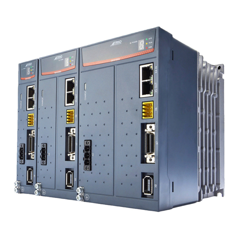
Intelligent Actuator RCON User manual

Catalog No. CE0264-1A (0619)
IAI Industrieroboter GmbH
Ober der Röth 4, D-65824 Schwalbach am Taunus, Germany
IAI (Shanghai) Co., Ltd.
Shanghai Jiahua Business Center A8-303, 808,
Hongqiao Rd., Shanghai 200030, China
IAI Robot (Thailand) Co., Ltd.
825 Phairojkijja Tower 7th Floor, Debaratana Rd.,
Bangna Nuea, Bangna, Bangkok 10260, Thailand
www.intelligentactuator.com
The information contained in this product brochure
may change without prior notice due to product improvements.
Please contact IAI for the latest information.
IAI America, Inc.
110 E. State Pkwy, Schaumburg, IL 60173 (800) 944-0333
1220 Kennestone Circle, Suite 108, Marietta, GA 30066 (888) 354-9470
US Headquarters: 2690 W. 237th Street, Torrance, CA 90505 (800) 736-1712
RCON
www.intelligentactuator.com

Gateway unit
PLC
Terminal unit
Actuator
Actuator Connectable
2-
axis
RCON is recommended for customers
who plan on using 2 axes or more.
Driver unit
22mm
is recommended for actuators with two axes or more.
Saves space inside
the control panel
Up to 2 axes of actuators can be connected to one RCON driver unit with 22mm width,
making it ideal for saving space in the control panel.
*3
*3 Minimum distance required for natural heat dissipation of the controller
PCON-CB x 16units
x 16-axis connection specication
1,010mm
223.4mm
30mm
179mm
115mm
Saves space by
85%
Up to 16 axes of actuators can be connected.
*1
16
axesmax.
8 driver units x 2 axes =
Driver unit x 16
*2 IAI product comparison
Saves up to 85% of control panel space.
*2
Select just as many
axes as necessary
*1 Actuator models
The maximum number of connectable axes diers
depending on (motor capacity / eld network
operation mode).
There will be no wasted space as driver units can be added in just the amount necessary.
Up to about 85% of control panel space can be saved, compared with models that connect a 1-axis actuator to a
single driver unit.
1

Gateway unit
PLC
Terminal unit
Actuator
Actuator Connectable
2-
axis
RCON is recommended for customers
who plan on using 2 axes or more.
Driver unit
22mm
is recommended for actuators with two axes or more.
Saves space inside
the control panel
Up to 2 axes of actuators can be connected to one RCON driver unit with 22mm width,
making it ideal for saving space in the control panel.
*3
*3 Minimum distance required for natural heat dissipation of the controller
PCON-CB x 16units
x 16-axis connection specication
1,010mm
223.4mm
30mm
179mm
115mm
Saves space by
85%
Up to 16 axes of actuators can be connected.
*1
16
axesmax.
8 driver units x 2 axes =
Driver unit x 16
*2 IAI product comparison
Saves up to 85% of control panel space.
*2
Select just as many
axes as necessary
*1 Actuator models
The maximum number of connectable axes diers
depending on (motor capacity / eld network
operation mode).
There will be no wasted space as driver units can be added in just the amount necessary.
Up to about 85% of control panel space can be saved, compared with models that connect a 1-axis actuator to a
single driver unit.
2

PCON-CB CC-Link specication x 16 units
PLC
PLC
Now, just one gateway is required.
Comparison example
For RCON
60% cost reduction
*4 IAI product comparison
*4
Reduces costs
by as much as 60% .
The conventional type ([Comparison example] below) requires network options installed to match the number of
controllers.
RCON can control driver units for up to 16 axes of actuators with a single gateway, allowing cost reductions up to
60% or so. It is especially recommended when using multiple axes.
A network option is required
for each controller.
CC-Link specication
high-output stepper
motor 16 axes
3

Can be connected to various eld networks.
PLC
Maintenance period reminders
Board replacement
period reminders
Rotation speed has dropped to 70%.
Fan unit
Driver unit
Actuator
Board replacement
period reminders
Fan replacement period reminders
Gateway unit
Capacitor capacitance has
dropped by 20%.
Capacitor life
sensor equipped
Capacitor life
sensor equipped
Patent
pending
Patent
pending
Capacitor capacitance has
dropped to 50%.
Motor temperature has exceeded
the set value due to motor overload,
grease depletion, wear on parts, etc.
Seven high-performance
functions that only IAI is
capable of delivering
High function
2
High function
1
Compatibility: No.1 in the industry with
seven eld network types supported
Predictive maintenance/preventative maintenance function
The RCON has a preventative maintenance function for the capacitor and a predictive maintenance function for the fan
unit and actuator.
Stop breakdowns
in advance!
PCON-CB CC-Link specication x 16 units
PLC
PLC
Now, just one gateway is required.
Comparison example
For RCON
60% cost reduction
*4 IAI product comparison
*4
Reduces costs
by as much as 60% .
The conventional type ([Comparison example] below) requires network options installed to match the number of
controllers.
RCON can control driver units for up to 16 axes of actuators with a single gateway, allowing cost reductions up to
60% or so. It is especially recommended when using multiple axes.
A network option is required
for each controller.
CC-Link specication
high-output stepper
motor 16 axes
4

Gateway unit
Fan unit
[RCON-FU]
Driver unit
Terminal unit
Connected axes
Controller interior
communication time
1~4-axis 1ms cycle
120
100
80
60
40
20
0
0 10 20 30 40 50 60
Operating temperature (°C)
With fan
Without fan
Install the optional fan unit to enable use in environments of 0 to 55°C without lowering actuator operating duty.
(one fan unit can be mounted across a driver unit and a terminal unit)
Controller interior communication time is 4ms even when 16 actuators are connected.
Controller interior communication time is 4ms cycle
PLC
5~9-axis 2ms cycle
10~14-axis 3ms cycle
15~16-axis 4ms cycle
Can also be easily
removed without
a tool.
(Retrotting is also
possible.)
High function
3
High function
4
Supports controller installation environment
temperatures of 0 to 55°C
Operating duty (%)
Field network
communication
5

Compatible with RCP2/3/4/5/6, RCA/2, RCD, RCL Series
Compatible with RCS2/3/4, IS(D)B, SSPA, LSA, NS, DDA Series
Large-capacity motor equipped actuator
RCON connection specication
SCON-CB/CGB
*
Expansion unit
(RCON-EXT)
Supports actuators equipped with a Battery-less absolute encoder as well as those with simple absolute and
incremental encoders.
When the SCON's RCON connection specication option (-RC) is selected, it can be connected to the RCON
expansion unit (RCON-EXT) to operate an actuator equipped with a large-capacity motor.
One RCON-EXT can connect to multiple SCON-CB controllers.
* IAI General Catalog product series / type model
Note that servo press actuator models, LSA-W21H, EC Series, SCARA robots,
TTA, ZR units and Wrist Units are not supported.
* As of December 2018
High function
5
No. 1 in the industry for number of supported actuators
(332 IAI actuator models ).
Connection cable CB-RE-CTL002
*Max. length 3m (CB-RE-CTLO30), total length
10m or less
Gateway unit
Fan unit
[RCON-FU]
Driver unit
Terminal unit
Connected axes
Controller interior
communication time
1~4-axis 1ms cycle
120
100
80
60
40
20
0
0 10 20 30 40 50 60
Operating temperature (°C)
With fan
Without fan
Install the optional fan unit to enable use in environments of 0 to 55°C without lowering actuator operating duty.
(one fan unit can be mounted across a driver unit and a terminal unit)
Controller interior communication time is 4ms even when 16 actuators are connected.
Controller interior communication time is 4ms cycle
PLC
5~9-axis 2ms cycle
10~14-axis 3ms cycle
15~16-axis 4ms cycle
Can also be easily
removed without
a tool.
(Retrotting is also
possible.)
High function
3
High function
4
Supports controller installation environment
temperatures of 0 to 55°C
Operating duty (%)
Field network
communication
6

All-axis motor power port
Single-axis motor power cuto
The following IAI 24V power supply (PSA-24) monitoring can be output to a PLC via RCON.
24V power supply (PSA-24)
*The graph is a reference image.
Output voltage Output current Power load factor Total energizing time
Internal temperature Low fan speed warning
Visualize power consumption
800
918[W]
[W]
600
400
200
0
0.5
Power supply peak power
Power supply rated power
Average power
1.0 1.5
[sec]
2.0 2.5
12[W]
0
Motor power cuto method can be selected.
Helps visualize equipment with 24V power monitor
PLC
Actuator single-axis
motor power cuto
Actuator all-axis
motor power cuto
Equipped with
communication
function to RCON
High function
6
High function
7
In accordance with customer safety function applications, the motor power (drive source) cuto method
at emergency stop can be selected through the RCON wiring method.
7

Each axis JOG (+/-) switch
USB port
Backward
Backward
Forward
Forward
Actuator
Home
(Coordinate: 0 mm)
Stroke end
Each axis brake release switch
Movable part
Actuator
Even without a teaching pendant or PC teaching software, each axis can be moved forward/backward.
Equipped with a brake release switch for each axis,
the movable parts can be moved by hand during
maintenance.
JOG switch enabled in manual mode, with PC software/
teaching pendant manual operation windows closed.
Connection to a PC is possible using
a commercial USB cable.
Dedicated cables are not required.
*Compatible with miniUSB (mini-B).
Forced brake
release
Enables easy start-up
and maintenance.
Movable
part
All-axis motor power port
Single-axis motor power cuto
The following IAI 24V power supply (PSA-24) monitoring can be output to a PLC via RCON.
24V power supply (PSA-24)
*The graph is a reference image.
Output voltage Output current Power load factor Total energizing time
Internal temperature Low fan speed warning
Visualize power consumption
800
918[W]
[W]
600
400
200
0
0.5
Power supply peak power
Power supply rated power
Average power
1.0 1.5
[sec]
2.0 2.5
12[W]
0
Motor power cuto method can be selected.
Helps visualize equipment with 24V power monitor
PLC
Actuator single-axis
motor power cuto
Actuator all-axis
motor power cuto
Equipped with
communication
function to RCON
High function
6
High function
7
In accordance with customer safety function applications, the motor power (drive source) cuto method
at emergency stop can be selected through the RCON wiring method.
8

<Selection example>
<Selection example>
SCON-CB
RCD RCP4 RCP2 RCA2 RCA2 RCP6
Controller Actuator
RCP2/3/4/5/6, RCA/2, RCD, RCL Series (24VDC)
<Selection example>
<24VDC>
<100/200VAC> ISB ISB
*Note that servo press actuator models, LSA-W21H, EC Series, SCARA robots, TTA, ZR units and Wrist Units cannot be connected.
Actuator selection
Selection Method
Step 1
Gateway unit selection
Select the gateway unit model from the network type.
Step 2
The actuator series are classied into two categories according to the table below.
<Selection example>
Gateway unit model
RCON-GW/GWG-DV
RCON-GW/GWG-CC
RCON-GW/GWG-CIE
RCON-GW/GWG-PR
RCON-GW/GWG-EC
RCON-GW/GWG-EP
RCON-GW/GWG-PRT
Network type
Select 1
Gateway unit
Gateway unit
16 axes of actuators can be connected to one gateway unit.
Gateway unit
+
×
Caution
RCD Series RCP4 Series RCP2 Series RCA2 Series RCA2 Series RCP6 Series ISB Series ISB Series
RCS2/3/4, IS(D)B, SSPA, LSA,
NS, DDA Series (100/200VAC)
Two
categories
Only one gateway unit can be connected per system.
When using two units or more, divide it into two.
One gateway
per system
* GW: Gateway unit of standard specications
GWG: Gateway unit of safety category type.
Contact IAI for additional safety category items (teaching pendant/TP adapter/
dummy plug/cable, etc.)
9

RCP4 RCP2
Actuator
External view Model Classication
Driver unit <Selection example>
RCON-PC-2
RCON-PC-1
RCON-PCF-1
RCON-AC-2
RCON-AC-1
RCON-DC-2
RCON-DC-1
1
1
-
1
-
-
1
2-axis specication
1-axis specication
1-axis specication
2-axis specication
1-axis specication
2-axis specication
1-axis specication
Stepper motor
RCP2
RCP3
RCP4
RCP5
RCP6
RCA
RCA2
RCL
2
5
10
20, 20S
30
RCD 3D
20P, 28P
35P, 42P
56P
56SP, 60P
86P
High thrust motor
Motor typeSeries
AC servo motor
DC brush-less motor
RCP6
RCA2 RCA2
RCD
2
*Connect to the RCON controller using a cable (CB-ADPC-MPA005).
The cable is supplied with the simple absolute unit.
Note: The ambient operating temperature of the simple absolute unit is within the range of 0~40°C.
* One simple absolute unit required per axis.
RCON-ABU-A RCON-ABU-P
Simple absolute unit selection
This is an example in which a 2-axis RCA2 Series actuator is selected for simple absolute specication.
<Selection example>
Driver unit Simple absolute unit
RCON-DC-1 RCON-PC-2 RCON-PC-1 RCON-AC-2 RCON-ABU-A x 2
Select 3
Driver unit selection
Step 3
Step 4
Select
2
Select
2
Select
2
Select
For actuators with simple absolute specication, select simple
absolute units (RCON-ABU-A/P) for the required number of axes.
Actuators to be made
compatible with
simple absolute
RCD
Series
RCP4
Series
RCP2
Series
RCP6
Series
RCA2
Series
RCA2
Series
Select the driver unit model number and required number of units according to the series name and motor type of the
actuator(s) to be connected to the RCON.
Number of axes
connected to actuator
Required
units
Simple absolute
battery
<Selection example>
<Selection example>
SCON-CB
RCD RCP4 RCP2 RCA2 RCA2 RCP6
Controller Actuator
RCP2/3/4/5/6, RCA/2, RCD, RCL Series (24VDC)
<Selection example>
<24VDC>
<100/200VAC> ISB ISB
*Note that servo press actuator models, LSA-W21H, EC Series, SCARA robots, TTA, ZR units and Wrist Units cannot be connected.
Actuator selection
Selection Method
Step 1
Gateway unit selection
Select the gateway unit model from the network type.
Step 2
The actuator series are classied into two categories according to the table below.
<Selection example>
Gateway unit model
RCON-GW/GWG-DV
RCON-GW/GWG-CC
RCON-GW/GWG-CIE
RCON-GW/GWG-PR
RCON-GW/GWG-EC
RCON-GW/GWG-EP
RCON-GW/GWG-PRT
Network type
Select 1
Gateway unit
Gateway unit
16 axes of actuators can be connected to one gateway unit.
Gateway unit
+
×
Caution
RCD Series RCP4 Series RCP2 Series RCA2 Series RCA2 Series RCP6 Series ISB Series ISB Series
RCS2/3/4, IS(D)B, SSPA, LSA,
NS, DDA Series (100/200VAC)
Two
categories
Only one gateway unit can be connected per system.
When using two units or more, divide it into two.
One gateway
per system
* GW: Gateway unit of standard specications
GWG: Gateway unit of safety category type.
Contact IAI for additional safety category items (teaching pendant/TP adapter/
dummy plug/cable, etc.)
10

For actuators to be connected to SCON-CB, select (1) to (3) below.
<Selection example>
x 1 unit
(1) Expansion unit (Model: RCON-EXT)
RCON expansion unit
RCON-EXT
max length 3m (030)
SCON-CB RC SCON-CB RC
<Selection example> I/O type
x 2 units
x Required number of units
Model: SCON- * - * * * - RC -*
Model: CB-RE-CTL
Total cable length may not exceed 10m
* 16 axes max.
* 100/200 VAC power supply for each SCON-CB RC
*
See P. 37
One cable (CB-ER-CTL002) is supplied as standard with SCON-CB for RCON connection.
(2) RCON connection specication SCON-CB
(3) RCON expansion unit to SCON-CB connection cable
Expansion unit selection
Step 5
4
Select
5
Select
RCON connection
specication
selected
Required for the number
of actuator axes to be
connected to SCON .
Must be separately
purchased only when
20 cm is too short.
When connecting SCON-CB and
RCON, one expansion unit is
required. One unit can connect to
multiple SCON-CB RC controllers.
Standard
accessory: 20 cm
Standard
accessory: 20 cm
SCON standard
accessory
SCON standard
accessory
11

Add up while checking the "Control Power Capacity List"below.
<Selection example>
<Selection example>
How to check
Gateway unit
Driver unit Simple absolute unitExpansion unit
RCON-DC-1 RCON-PC-2RCON-GW-CC RCON-EXT RCON-PC-1 RCON-AC-2 RCON-ABU-A x 2
RCD
SCON RCP4 RCP2 RCA2 RCA2RCP6
Without brake Without brake Without brakeWith brake
0.8A +0.1A + 0.2A + 0.2A + 0.4A + 0.2A +(0.2A x 2 axes)=2.3A < 9.0A
(Conrmed to be less than 9.0A. If larger than 9.0A, another gateway unit is required.)
Item Specications
Power supply voltage 24VDC±10%
Gateway unit (includes terminal unit) 0.8A
0.2A
0.4A
0.6A
0.1A
0.2A
Expansion unit
Simple absolute unit (common to all types)
Brake: No
Brake: Yes (1-axis specication)
Brake: Yes (2-axis specication)
x 1unit
x 1unit
x 1unit
x 2axes
Control power (CP)
( )
Control Power Capacity List
Calculating various unit control power capacities (CP)
Step 6
OK
Make sure that the total control power capacity of the
various units selected so far is within 9.0A.
Per driver unit
Gateway unit
Simple
absolute
specication
for 2 axes
Control power (CP)
9.0A or less
Control power
capacity (CP)
Driver unit
(common for
all types)
Current limit value
9.0A or less
For actuators to be connected to SCON-CB, select (1) to (3) below.
<Selection example>
x 1 unit
(1) Expansion unit (Model: RCON-EXT)
RCON expansion unit
RCON-EXT
max length 3m (030)
SCON-CB RC SCON-CB RC
<Selection example> I/O type
x 2 units
x Required number of units
Model: SCON- * - * * * - RC -*
Model: CB-RE-CTL
Total cable length may not exceed 10m
* 16 axes max.
* 100/200 VAC power supply for each SCON-CB RC
*
See P. 37
One cable (CB-ER-CTL002) is supplied as standard with SCON-CB for RCON connection.
(2) RCON connection specication SCON-CB
(3) RCON expansion unit to SCON-CB connection cable
Expansion unit selection
Step 5
4
Select
5
Select
RCON connection
specication
selected
Required for the number
of actuator axes to be
connected to SCON .
Must be separately
purchased only when
20 cm is too short.
When connecting SCON-CB and
RCON, one expansion unit is
required. One unit can connect to
multiple SCON-CB RC controllers.
Standard
accessory: 20 cm
Standard
accessory: 20 cm
SCON standard
accessory
SCON standard
accessory
12

Motor Power Capacity List
Actuator/driver unit
Item Motor typeSeries
Max. current
-
-
-
3.9A
-
3.3A
4.4A
4.4A
5.1A
4.0A
4.6A
6.4A
6.4A
1.5A
-
-
-
-
0.8A
1.9A
1.9A
2.3A
With PowerCON
20P/20SP/28P
56SP/60P/
86P
RCP2
RCP4
RCP5
RCP6
28P*
5W
10W
20W
20W(20S)
30W
2W
5W
10W
RCA
RCA2
RCL
RCD 3W
x 2axes
x 2axes
x 1axis
x 1axis
<Selection example>
Driver unitGateway unit
RCON-DC-1 RCON-PC-2RCON-GW-CC RCON-PC-1 RCON-AC-2
RCD
3W
Actuator
Series
Motor type
RCP4
28P
RCP2
20P
RCA2
20W
RCA2
20W
RCP6
35P
1.5A + 3.9A +0.8A + 3.9A +4.4A + 4.4A =
18.9A < 37.5A
(Conrmed to be less than 37.5A. If larger than 37.5A, another gateway unit is required.)
Stepper motor
RCON-PC
Stepper motor
RCON-PCF
AC servo motor
RCON-AC
DC brush-less motor
RCON-DC Standard
( )
How to check
28P/35P/42P/
42SP/56P
RCP4
RCP5
RCP6
5.7A
-
2.5A
2.5A
3.4A
2.2A
-
-
-
-
1.0A
1.3A
1.3A
1.7A
1.3A
0.8A
1.0A
1.3A
0.7A
-
* Applicable models: RCP2-RA3, RCP2-RGD3
Calculating various unit motor power capacities (MP)
Step 7 Gateway unit
OK
Make sure that the total motor power capacity of the driver units
selected so far is within 37.5A.
Add up while checking the "Motor Power Capacity List"below. If the
maximum current is listed, add the maximum current. If not, add the
rated current.
* Do not include the 100/200 VAC power supply to SCON-CB RC.
Rated
current
Motor power
capacity (MP)
Per 1-axis
actuator Standard / High
accel/decel /
Energy saving
Standard /
Hi-accel./decel.
Without
PowerCON
Without
PowerCON
Motor power (MP)
Current limit value
37.5 A or less
Motor power (MP)
37.5 A or less
<Selection
example>
When energy-
saving is set
Standard /
Hi-accel./decel.
RCP2
RCP3
Without
PowerCON
13

<Selection example>
<Selection example>
4 driver units ÷ 2 = 2 units Fan unit [RCON-FU]
1 6
Order using the model name for each unit.
Gateway unit (2 fan units included)
[RCON-GW-CC-FU2]
Expansion unit [RCON-EXT]
Driver unit [RCON-DC-1]
Driver unit [RCON-PC-2]
Driver unit [RCON-PC-1]
Driver unit [RCON-AC-2]
Simple absolute unit [RCON-ABU-A] x 2
RCON connection specication SCON
[SCON-*-***-RC] x 2
4
2
2
2
2
3
5
Fan unit selection
Step 8
Step 9 Unit models to be ordered
5 5
6 6
222241 1
3 3
6
Select
If the controller installation environment may exceed 40°C, a fan unit will be required. (Up to 55°C)
The number of fan units is the total number of driver units divided by 2.
If the total number of driver units is an odd number, add 1 to the total number and divide it by 2 (The last fan will connect to
the last driver card and the terminal unit).
When ordering, be sure to specify the gateway unit model.
Note: The ambient operating temperature of the simple absolute unit is
within the range of 0~40°C even when a fan unit is installed.
See pages 33 to 34 for applicable cables for each actuator.
Motor Power Capacity List
Actuator/driver unit
Item Motor typeSeries
Max. current
-
-
-
3.9A
-
3.3A
4.4A
4.4A
5.1A
4.0A
4.6A
6.4A
6.4A
1.5A
-
-
-
-
0.8A
1.9A
1.9A
2.3A
With PowerCON
20P/20SP/28P
56SP/60P/
86P
RCP2
RCP4
RCP5
RCP6
28P*
5W
10W
20W
20W(20S)
30W
2W
5W
10W
RCA
RCA2
RCL
RCD 3W
x 2axes
x 2axes
x 1axis
x 1axis
<Selection example>
Driver unitGateway unit
RCON-DC-1 RCON-PC-2RCON-GW-CC RCON-PC-1 RCON-AC-2
RCD
3W
Actuator
Series
Motor type
RCP4
28P
RCP2
20P
RCA2
20W
RCA2
20W
RCP6
35P
1.5A + 3.9A +0.8A + 3.9A +4.4A + 4.4A =
18.9A < 37.5A
(Conrmed to be less than 37.5A. If larger than 37.5A, another gateway unit is required.)
Stepper motor
RCON-PC
Stepper motor
RCON-PCF
AC servo motor
RCON-AC
DC brush-less motor
RCON-DC Standard
( )
How to check
28P/35P/42P/
42SP/56P
RCP4
RCP5
RCP6
5.7A
-
2.5A
2.5A
3.4A
2.2A
-
-
-
-
1.0A
1.3A
1.3A
1.7A
1.3A
0.8A
1.0A
1.3A
0.7A
-
* Applicable models: RCP2-RA3, RCP2-RGD3
Calculating various unit motor power capacities (MP)
Step 7 Gateway unit
OK
Make sure that the total motor power capacity of the driver units
selected so far is within 37.5A.
Add up while checking the "Motor Power Capacity List"below. If the
maximum current is listed, add the maximum current. If not, add the
rated current.
* Do not include the 100/200 VAC power supply to SCON-CB RC.
Rated
current
Motor power
capacity (MP)
Per 1-axis
actuator Standard / High
accel/decel /
Energy saving
Standard /
Hi-accel./decel.
Without
PowerCON
Without
PowerCON
Motor power (MP)
Current limit value
37.5 A or less
Motor power (MP)
37.5 A or less
<Selection
example>
When energy-
saving is set
Standard /
Hi-accel./decel.
RCP2
RCP3
Without
PowerCON
14

Model Specication Items
EXT ABU
RCON
SCON
RCON
RCON RCON
Type
Type
Type
Expansion Absolute Unit
RC 0
I/O Type
Motor Type Power Supply
Voltage
Number of
Axes
Type
Options
Encoder Type Options I/O Type I/O Cable Length
Series
Series
Series Series
GW Standard type
GWG Safety category spec type
PStepper motor
AAC servo motor
CC-Link connection specication
CC
CIE CC-Link IE Field connection specication
DV DeviceNet connection specication
EP EtherNet/IP connection specication
EC EtherCAT connection specication
PR PROFIBUS-DP connection specication
PRT PROFINET IO connection specication
1-axis specication
1
2-axis specication2
PC Stepper motor
PCF High thrust stepper motor
AC AC servo motor
DC DC brush-less motor
(1) Gateway unit
(5) SCON controller (RCON connection specication)
(2) Driver unit
(3) Expansion unit (4) Simple absolute unit
Type: PC
1.2A motor
1-axis
2-axis
20P
20SP
28P
35P
42P
42SP
56P
20stepper motor
20stepper motor (For RA2AC/RA2BC)
28stepper motor
35stepper motor
42stepper motor
42stepper motor (For RCP4-RA5C)
56stepper motor
Type: PCF
4A motor
1-axis
56SP
60P
86P
56high thrust stepper motor
60high thrust stepper motor
86high thrust stepper motor
Type: AC
2-30W motor
1-axis
2-axis
2
5
10
20
20S
30
2W servo motor
5W servo motor
10W servo motor
20W servo motor
20W servo motor (For RCA2-SA4/RCA-RA3)
30W servo motor
Type: DC
3D motor
1-axis
2-axis
3D 2.5W DC brush-less motor
(1)
(3) (4)
(2)
*Type: Only 1-axis can be selected for PCF
Fan unit mounting (: Specify the number of units, 1 ~ 8)FU
TRN Without terminal unit
* A terminal unit is required during operation.
* “-FU” can be deleted if fan unit is ordered separately.
Ex. RCON-GW-EP-FU2 is equal to RCON-GW-EP and RCON-FU (2 qty).
Contact IAI for model selection items
Only SCON-C RC option can be connected to RCON-EXT.
15

System Conguration
Field network
DeviceNet, CC-Link,
CC-Link IE Field, EtherCAT,
EtherNet/IP,
PROFIBUS-DP, PROFINET IO
RCON connection
specication
SCON controller
[I/O type: RC]
(Please contact IAI for
more details)
PC teaching software
(See P. 30)
<Model: IA-OS>
<Model: RCM-101-MW/USB>
Options
24 V power supply
(See P. 31)
<Model: PSA-24(L)>
Options
Connection cable
(See P. 37)
<Model: CB-RE-CTL002>
Supplied with SCON-CB (RC specication)
Drive source shuto connector
(See P. 32)
<Model: DFMC1.5/2-STF-3.5>
Supplied with driver unit
System I/O connector
(See P. 32)
<Model: DFMC1.5/
5-ST-3.5>
Included with gateway
unit
Connection cable
(See P. 35)
<Model:
CB-ADPC-MPA005>
Supplied with simple absolute unit
Terminal connector
(See P. 31)
<Model: RCON-EXT-TR>
Supplied with expansion unit
Options
Touch panel teaching
pendant
(See P. 30)
Options
Fan unit
(See P. 32)
<Model: RCON-FU>
Options
Simple absolute unit
(See P. 25)
<Model: RCON-ABU-P
(For stepper motor)>
<Model: RCON-ABU-A
(For AC servo motor)>
Motor/encoder cable*
RCS2/3/4
Series
Connectable actuators
100/200VAC 24VDC
RCP2/3/4/5/6 Series RCA/2 Series RCD SeriesDDA Series
LSA Series
IS(D)B Series
SSPA Series
* Refer to page 25 for actuators that
cannot be connected.
*The 100/200 VAC motor/encoder cable is supplied with the actuator.
The motor/encoder cables are dierent according to the actuator type to be connected.
Refer to page 33 if conversion cables need to be prepared.
Supplied with GWG specication
Dummy plug
(See P. 32)
<Model: DP-5>
For IA-OS: USB cable
For RCM-101:
Supplied with PC teaching
software
<Model: TB-02><Model: TB-03>
16

System CongurationUnit Conguration
The RCON has a modular conguration. Connect each unit under the following conditions.
Gateway unit Driver unit Terminal unitExpansion unit
Unit name Number of connected units Location
Gateway unit 1 Placed at far left
Expansion unit 1 Placed to right of gateway unit
Driver unit 16 axes max.*Placed to left of terminal unit
Terminal unit 1 Placed at far right
Product name Model Reference page
Gateway unit
(GWG: Safety category type)
DeviceNet connection specication RCON-GW/GWG-DV P. 20
CC-Link connection specication RCON-GW/GWG-CC P. 20
CC-Link IE Field connection specication RCON-GW/GWG-CIE P. 21
PROFIBUS-DP connection specication RCON-GW/GWG-PR P. 21
EtherCAT connection specication RCON-GW/GWG-EC P. 22
EtherNet/IP connection specication RCON-GW/GWG-EP P. 22
PROFINET IO connection specication RCON-GW/GWG-PRT P. 23
Expansion unit
For SCON-CB connection RCON-EXT P. 25
Terminal connector (for SCON-CB) RCON-EXT-TR P. 32
Driver unit
Stepper motor 1-axis specication RCON-PC-1
P. 24
Stepper motor 2-axis specication RCON-PC-2
High thrust stepper motor 1-axis specication RCON-PCF-1
AC servo motor 1-axis specication RCON-AC-1
AC servo motor 2-axis specication RCON-AC-2
DC brush-less motor 1-axis specication RCON-DC-1
DC brush-less motor 2-axis specication RCON-DC-2
Terminal unit Included with gateway unit RCON-GW-TR P. 25
Simple absolute unit
(1-axis specication)
For RCON-PC RCON-ABU-P
P. 25
For RCON-AC RCON-ABU-A
Fan unit One for every two driver units RCON-FU P. 32
* · Driver units can be rearranged.
· The maximum number of connectable axes varies depending on the operation mode.
For details, refer to “Maximum number of connectable axes (page 26)”.
Unit name and single product model number list
17

General Specications
Item Specications Details page
Power supply voltage 24VDC ±10% -
Power supply current Differs with system conguration P. 19
Number of axes controlled 1 to 16 axes *For maximum axes, refer to “Maximum number of connectable axes” P. 26
Encoder resolution
[pulse/r]
Stepper motor
Incremental 800
-
Battery-less Absolute
RCP4/RCP5 800
RCP6 8192
AC servo motor
Incremental
RCA
800
Battery-less Absolute 16384
Incremental
RCA2-***N/NA 1048
Excluding RCA2-***N/NAN 800
DC brush-less motor Incremental
RCD-RA1R/GRSN 400
RCD-RA1DA/GRSNA 480
Supported eld networks DeviceNet, CC-Link, CC-Link IE Field, PROFIBUS-DP,
EtherCAT, EtherNet/IP, PROFINET IO
Conguration units Gateway unit, driver unit, expansion unit,
simple absolute unit P. 20
SIO interface
Teaching port
Communication method RS485
-
Communication speed 9.6/19.2/38.4/57.6/115.2/230.4kbps
USB port
Communication method USB
Communication speed 12Mbps
Emergency stop/Enable operation Collective system support with gateway unit STOP signal input, equipped with connectors capable of
shutting off the drive power supply to individual axes of each driver unit -
Data recording device Position data and parameters are saved in non-volatile memory
(Unlimited rewrites) -
Calendar function Retention function: About 10 days Charging time: About 100 hours -
Safety category compliance B (The safety category specication supports up to category 4 external circuits) -
Protection functionality Overcurrent, abnormal temperature, encoder disconnection, overload -
Preventative/predictive maintenance
function Low electrolytic capacitor capacity and low fan rotation speed -
Ambient operating temperature 0~55°C *0~40°C for simple absolute units -
Ambient operating humidity 85% RH or less, non-condensing -
Operating atmosphere Avoid corrosive gas and excessive dust -
Vibration resistance Frequency: 10~57Hz / Amplitude: 0.075mm, Frequency: 57~150Hz / Acceleration: 9.8m/s2
XYZ directions Sweep time: 10 minutes Number of sweeps: 10 times -
Shock resistance Drop height: 800mm 1 corner, 3 edges, 6 faces -
Electric shock protection mechanism Class III -
Degree of protection IP20 -
Insulation withstanding voltage 500VDC 10MΩ -
Generated heat
(per unit)
RCON-PC
PowerCON: No 5.0W
-
PowerCON: Yes 8.0W
RCON-PCF PowerCON: No 19.2W
RCON-AC Standard / High accel/decel / Energy saving 4.5W
RCON-DC Standard 3.0W
Cooling method Natural cooling and forced cooling by fan unit (option) -
Connections between each unit Unit connection method -
Installation/mounting method DIN rail (35mm) mounting -
Regulations/standards CE Marking, UL Certication (planned), RoHS -
18

Power Capacity
Item Specications
Power supply voltage 24VDC±10%
Control power capacity
(per unit)
Gateway unit
(includes terminal unit) 0.8A
Driver unit
(common for all types)
Brake: No 0.2A
Brake: Yes (1-axis specication) 0.4A
Brake: Yes (2-axis specication) 0.6A
Expansion unit 0.1A
Simple absolute unit (common to all types) 0.2A
Motor power capacity
(per 1-axis actuator)
Actuator/driver unit
Rated
current
Max. current
Series Motor type When energy-
saving is set
Stepper motor/
RCON-PC
RCP2
RCP3
20P/20SP/28P
Without PowerCON
0.8A - -
28P*1.9A - -
RCP4
RCP5
RCP6
28P/35P/42P/
42SP/56P
Without PowerCON 1.9A - -
With PowerCON 2.3A - 3.9A
Stepper motor/
RCON-PCF
RCP2
RCP4
RCP5
RCP6
56SP/60P/86P Without PowerCON 5.7A - -
AC servo motor/
RCON-AC
RCA
RCA2
5W Standard / Hi-accel./decel. 1.0A - 3.3A
10W
Standard / High accel/decel /
Energy saving
1.3A 2.5A 4.4A
20W 1.3A 2.5A 4.4A
20W(20S) 1.7A 3.4A 5.1A
30W 1.3A 2.2A 4.0A
RCL
2W
Standard / Hi-accel./decel.
0.8A - 4.6A
5W 1.0A - 6.4A
10W 1.3A - 6.4A
DC brush-less motor/
RCON-DC RCD 3W Standard 0.7A - 1.5A
Item Current limit value
Control power 9.0A or less
Motor power 37.5A or less
Based on the connection conguration, make sure for each unit that the calculated results for control power and
motor power do not exceed the current limit value for selection calculation.
Power supply capacity by unit
· For operation patterns where acceleration/deceleration operation is performed simultaneously on all axes, and where
operating duty is 100%: Motor power must be calculated at the maximum current value.
(If the maximum current is not listed, calculate with the rated current.)
Caution
* Applicable models: RCP2-RA3, RCP2-RGD3
* Do not include the power supply to SCON-CB RC.
19
Table of contents
Popular Control System manuals by other brands
Conviron
Conviron CMP6050 Operator's manual
Toshiba
Toshiba BMS-SM1280HTLE Service manual

Balboa
Balboa Revolution System Overview Manual
Mountz
Mountz E-DRIV MD-Series CALIBRATION PROCEDURE
Idex
Idex Knight ILCS EDGE installation manual
Magnetic Autocontrol
Magnetic Autocontrol MAGSTOP MBE35 operating instructions
