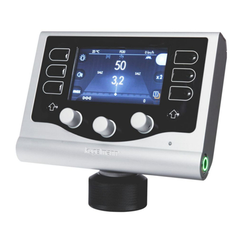
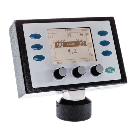
Kugelmann K-BASIC 2 User manual

// ORIGINAL OPERATING INSTRUCTIONS
Art.Nr.: 10041948 25.04.2019 | Version 1.4 | EN
Kugelmann Maschinenbau e.K.
Gewerbepark 1-5
87675 Rettenbach a.A.
GERMANY
www.kugelmann.com
+49 (0) 8860 | 9190-0
Kugelmann Maschinenbau is a family-run Allgäu business with its main emphasis and
tradition in municipal technology. With passion, we manufacture reliable and pioneering
machines - we love what we do.
ORIGINAL OPERATING INSTRUCTIONS
Control system
K-BASIC 2

// ORIGINAL OPERATING INSTRUCTIONS
Copyrights and trademarks 25.04.2019 2/54
Copyrights and trademarks
© Kugelmann Maschinenbau e.K.
Gewerbepark 1-5
87675 Rettenbach a.A.
Tel.: +49 (0) 8860 / 9190-0
Fax: +49 (0) 8860 / 9190-19
Mail: office@kugelmann.com
Web: www.kugelmann.com
All company names and designations used in this manual may also be registered trademarks
of the respective manufacturing companies and shall not be used commercially or otherwise.
Errors and omissions excepted.
All rights reserved. No part of this manual shall be reproduced or copied in any form (printing,
photocopying, storing or distribution in electronic form) without prior written consent of
Kugelmann Maschinenbau e.K.
We are constantly developing our products to offer our customers maximum convenience.
Therefore, we ask for your understanding that the manual can deviate from the product in some
regards.

// ORIGINAL OPERATING INSTRUCTIONS
Content 25.04.2019 3/54
2 Content
1 Title............................................................................................................. 1
2 Content........................................................................................................3
3 General information.....................................................................................5
3.1 Service information......................................................................................................................5
3.2 EC Declaration of Conformity.......................................................................................................6
4 Introduction.................................................................................................7
4.1 Target group.................................................................................................................................7
4.2 Application...................................................................................................................................7
4.3 Conventions used.........................................................................................................................8
4.4 Change history............................................................................................................................. 8
5 General description......................................................................................9
5.1 Components of the control system............................................................................................10
5.2 User interface............................................................................................................................ 11
5.3 Control variants..........................................................................................................................13
5.4 Setup menu................................................................................................................................14
5.5 Designated use...........................................................................................................................15
5.6 Obvious misuse..........................................................................................................................15
5.7 Wear parts................................................................................................................................. 16
6 Safety instructions......................................................................................17
6.1 General safety instructions........................................................................................................ 17
6.2 Commissioning...........................................................................................................................18
6.3 Use............................................................................................................................................. 19
6.4 Maintenance..............................................................................................................................19
6.5 Designations.............................................................................................................................. 21

// ORIGINAL OPERATING INSTRUCTIONS
Content 25.04.2019 4/54
7 Commissioning...........................................................................................22
7.1 Wiring diagram.......................................................................................................................... 23
7.2 Start/finish setup menu............................................................................................................. 25
7.3 Regulation equipment............................................................................................................... 26
7.4 Configuration of drive signal......................................................................................................26
7.5 Simulation speed....................................................................................................................... 28
7.6 Checking and setting of sensors.................................................................................................28
7.7 Regulator adjustment................................................................................................................ 30
7.8 Weighing of spreading materials............................................................................................... 31
7.9 Number of screws......................................................................................................................33
7.10 Configuration of spreading width............................................................................................ 33
7.11 Stop of spreading disc when vehicle stops.............................................................................. 35
7.12 Stop of spreading disc at pause............................................................................................... 35
7.13 Electrical monitoring of spreading process..............................................................................36
7.14 Rotating beacon.......................................................................................................................36
7.15 Working headlight....................................................................................................................37
7.16 Spreading protocol...................................................................................................................37
7.17 Boost function..........................................................................................................................38
7.18 Reset to factory settings.......................................................................................................... 39
7.19 Recommissioning.....................................................................................................................40
8 Operating instructions................................................................................41
8.1 Info menu...................................................................................................................................42
8.2 Update....................................................................................................................................... 44
8.3 Error codes.................................................................................................................................45
8.4 Requirements for carrier vehicle............................................................................................... 49
9 Storage.......................................................................................................50
10 Technical Data.......................................................................................... 51
11 Disconnecting the system.........................................................................52
Warranty...................................................................................................... 53

// ORIGINAL OPERATING INSTRUCTIONS
General information 25.04.2019 5/54
3 General information
This chapter gives you information on the following:
•Chapter 3.1 "Service information", page 5
•Chapter 3.2 "EC Declaration of Conformity", page 6
3.1 Service information
Customer service:
Tel.: +49 (0) 8860 / 9190-90
Fax: +49 (0) 8860 / 9190-49
E-Mail: [email protected]

// ORIGINAL OPERATING INSTRUCTIONS
General information 25.04.2019 6/54
3.2 EC Declaration of Conformity
in terms of the EC Machinery Directive 2006/42/EC and
the EMC Directive 2014/30/EU
We herewith declare that the control system designated below complies with the
relevant essential health and safety requirements of the respective EC Machine
Directives and the EMC Directive due to its design and construction, and in the
version supplied by us.
If the control system is modified without our consent, this declaration shall cease to
apply.
Designation: Control system k-basic 2
Relevant EC machinery directives:
DIN EN ISO 15431 / 16330/292-1 / 292-2 / 60204-1 / 12100 / 13849-1 / 13849-2
Rettenbach a.A., December 2016 Josef Kugelmann

// ORIGINAL OPERATING INSTRUCTIONS
Introduction 25.04.2019 7/54
4 Introduction
This chapter gives you information on the following:
•Chapter 4.1 "Target group", page 7
•Chapter 4.2 "Application", page 7
•Chapter 4.3 "Conventions used", page 8
•Chapter 4.4 "Change history", page 8
4.1 Target group
These operating instructions are intended for skilled persons who are responsible for
the following work at the control system:
•Commissioning
•Control
•Operation
•Use
At least once a year, all personnel must be trained in the operation of the control
system in accordance with the guidelines of the business liability insurance. The use
of the control system by untrained or unauthorized persons is prohibited.
4.2 Application
These operating instructions contain all necessary data and information for safe
operation and commissioning of the spreader.
Make sure that all persons responsible for operation of the control system or persons
working in the immediate environment of the control system are familiar with the
operating instructions as well as the safety information in this manual.
These operating instructions are part of the product and have to be kept in a safe
place. In case of resale or transfer of the control system to third parties, these
operating instructions have to be included.
All information, illustrations and technical data correspond to the technical state at
the time of printing. Subject to technical modifications.

// ORIGINAL OPERATING INSTRUCTIONS
Introduction 25.04.2019 8/54
4.3 Conventions used
This manual uses the following typographic conventions:
Symbol Signal
word Meaning
Danger
Indicates an imminent dangerous situation, which - in case of
non-observance of the safety instructions - will entail death or
grievous bodily harm.
Warning
Indicates a possibly dangerous situation, which - in case of non-
observance of the safety instructions - may entail death or
grievous bodily harm.
Caution
Indicates a possibly dangerous situation, which - in case of non-
observance of the safety instructions - may result in minor
injuries or damage to property.
Notice Contains useful information with respect to proper handling of
the machine.
4.4 Change history
Date Version Modification
January 13,
2016
1.1 First edition
Oct 14,
2016
1.2 Software modifications
Dec 6, 2016 1.3 Software modifications in the setup menu
Apr 25,
2019
1.4 Setup menu revised

// ORIGINAL OPERATING INSTRUCTIONS
General description 25.04.2019 9/54
5 General description
This chapter gives you information on the following:
•Chapter 5.1 "Components of the control system", page 10
•Chapter 5.2 "User interface", page 11
•Chapter 5.3 "Control variants", page 13
•Chapter 5.4 "Setup menu", page 14
•Chapter 5.5 "Designated use", page 15
•Chapter 5.6 "Obvious misuse", page 15
•Chapter 5.7 "Wear parts", page 16

// ORIGINAL OPERATING INSTRUCTIONS
General description 25.04.2019 10/54
5.1 Components of the control system
Please see the following illustration for components of the control system:
Pos. Part
10 Turning knob
20 Membrane keyboard
30 Side plate (lh)
40 Side plate (rh)
50 ON / OFF push-button
60 Housing front shell
70 Printed circuit board (PCB)
80 Housing rear shell
90 Fixture
100 Spherical head
110 Counternut
120 Locking nut

// ORIGINAL OPERATING INSTRUCTIONS
General description 25.04.2019 11/54
5.2 User interface
Active command
Disabled
command
Pos. No. Key command
10 Setting of spreading width
20 Setting of spreading density
30 •Orange -> Warning
•Red -> Error
40 Rotating beacon / Flasher
50 Working headlight
60 Speed and spreading quantity resulting from V Sim
70 Double spreading density
80 Chute sensor
90 Electrical spreading pattern control
100
•Upper LED lights up if V=10 km/h is exceeded and goes out if the speed falls
below V=5 km/h
•Lower LED lights up if a drive signal has been recognized
110 Spreading operation / Pause
120 USB interface for software update
130 ON / OFF
140
150
•Glowing permanently in case of error-free operation
•Flashing in case of undersupply or oversupply

// ORIGINAL OPERATING INSTRUCTIONS
General description 25.04.2019 12/54
Pos. No. Key command
10 Adjustment of spreading width
20 Adjustment of spreading density
30 RS 232 plug for data protocol
40 Workshop display
50 Trigger button -> actuation at the front
60 Drive signal / current supply
70 Coupling for slave connecting cable
80 Navigation keys -> actuation at the front

// ORIGINAL OPERATING INSTRUCTIONS
General description 25.04.2019 13/54
5.3 Control variants
Three different control variants are available:
1 Basic variant with operation/pause control via key
2 Start/stop function:
➯Regulation via drive signal of carrier vehicle:
– Regardless of speed -> same spreading rate, different spreading
density.
– Standstill -> no spreading.
3 Path-dependence:
➯Drive signal is detected via speedometer or a sensor with punched
disk at the carrier vehicle:
– Spreading rate proportional to speed.
– Setting of spreading density.
– Standstill -> no spreading.
Hinweis
Drive signal at carrier vehicle.
•Please see the operating instructions of the carrier vehicle for the position where
the drive signal is taken.

// ORIGINAL OPERATING INSTRUCTIONS
General description 25.04.2019 14/54
5.4 Setup menu
1 screw 2 screws Description
Installed software version.
Regulation equipment of the device (see Chapter 7.3 "Regulation equipment",
page 26).
Adjustment of drive signal (see Chapter 7.4 "Configuration of drive signal",
page 26).
Setting of simulated speed (see Chapter 7.5 "Simulation speed", page 28).
Check sensors (see Chapter 7.6 "Checking and setting of sensors", page 28).
Recording characteristic curve of spreading disc (see Chapter 7.7 "Regulator
adjustment", page 30).
Recording characteristic curve of conveyor screw(s) (see Chapter 7.7 "Regulator
adjustment", page 30).
Checking of spread quantity (see Chapter 7.8 "Weighing of spreading materials",
page 31).
Fine correction of spread quantity (see Chapter 7.8 "Weighing of spreading
materials", page 31).
Number of metering screws (see Chapter 7.9 "Number of screws", page 33).
Fine correction of spreading width (see Chapter 7.10 "Configuration of spreading
width", page 33).
Stop of spreading disc in case of vehicle stop (see Chapter 7.11 "Stop of spreading
disc when vehicle stops", page 35).
Stop of spreading disc in case of pause (see Chapter 7.12 "Stop of spreading disc
at pause", page 35).
Electrical monitoring of spreading process (see Chapter 7.13 "Electrical monitoring
of spreading process", page 36).
Rotating beacon (see Chapter 7.14 "Rotating beacon", page 36).
Working headlight (see Chapter 7.15 "Working headlight", page 37).
Possibility to record and assemble a spreading protocol (see Chapter 7.16
"Spreading protocol", page 37).
Increased spreading output when starting (see Chapter 7.17 "Boost function",
page 38).
Time of increased spreading output when starting (see Chapter 7.17 "Boost
function", page 38).
Quantity of spreading material in the set time (see Chapter 7.17 "Boost function",
page 38).
Reset to standard settings (see Chapter 7.18 "Reset to factory settings",
page 39).
Update (see Chapter 8.2 "Update", page 44).

// ORIGINAL OPERATING INSTRUCTIONS
General description 25.04.2019 15/54
5.5 Designated use
Use the control system only for spreaders manufactured by Kugelmann
Maschinenbau e.K.
Use the control system only with the plug-and-socket connections provided for this
purpose and with the respective original cables.
Any kind of use that deviates from the procedure set forth herein is considered
contrary to its designated use. The operator of the control system is liable for any
damages arising from such action.
Use and reconditioning of the control system may only be carried out by trained and
competent personnel.
To operate the equipment within the limits of its designated use, please note the
following:
•These operating instructions as well as all other enclosed documentation.
•The relevant accident prevention regulations.
•The generally recognised rules relating to technical safety requirements and
occupational health.
•The operating instructions of the carrier vehicle.
5.6 Obvious misuse
It is not allowed to operate machines with the control system which were not
designed and manufactured by Kugelmann Maschinenbau e.K.
Do not use or store the control system outside or uncovered.
The control system shall not be used as handle.

// ORIGINAL OPERATING INSTRUCTIONS
General description 25.04.2019 16/54
5.7 Wear parts
Hinweis
Wear parts are:
•Potentiometer for:
– Spreading density
– Spreading width
•Membrane keyboard
•ON/OFF push-button
•Rotary control for:
– Spreading density
– Spreading width
•Lighting
– Rotating beacon
– Working headlight
•Connector

// ORIGINAL OPERATING INSTRUCTIONS
Safety instructions 25.04.2019 17/54
6 Safety instructions
This chapter gives you information on the following:
•Chapter 6.1 "General safety instructions", page 17
•Chapter 6.2 "Commissioning", page 18
•Chapter 6.3 "Use", page 19
•Chapter 6.4 "Maintenance", page 19
•Chapter 6.5 "Designations", page 21
6.1 General safety instructions
Warning
Use of the control system by untrained persons.
Risk of serious injury.
•Make sure that all persons responsible for operation or maintenance of the
control system are trained in the operation of the device and are familiar with the
operating instructions as well as the safety information in this manual!
•Insist on compliance with the applicable safety regulations!
Warning
Non-observance of guidelines.
Risk of serious injury or death.
•Please observe the regulations relating to accident prevention!
•Please observe the generally applicable safety regulations, industrial standards
and medical guidelines!
•Please observe the road transport guidelines!
•Please pay attention to the general advice in these operating instructions!

// ORIGINAL OPERATING INSTRUCTIONS
Safety instructions 25.04.2019 18/54
Caution
Changes at the control system.
Impairment of functionality and danger of property damage.
•Do not make any changes at the control system!
6.2 Commissioning
Caution
First commissioning without instruction.
Risk of injury or property damage.
•First commissioning of the control system must be accomplished by employees of
the dealer, the manufacturer or a representative of our works!
Caution
Wrong polarity.
Danger of property damage.
•Check the polarity prior to commissioning.
Caution
Damaged power lines.
Risk of injury or property damage.
•Damaged power lines have to be replaced immediately!
Caution
Commissioning without making sure that the machine is in perfect technical
condition.
Risk of injury or property damage.
•Check all important parts before commissioning!
•Check all safety-related protection devices before commissioning!
•If applicable, please replace damaged parts!

// ORIGINAL OPERATING INSTRUCTIONS
Safety instructions 25.04.2019 19/54
Caution
Improper fixing of control system.
Danger of property damage.
•Make sure that the control system is fixed at an appropriate place designated for
this purpose!
6.3 Use
Caution
Non-observance of regulations concerning road safety.
Risk of injury or property damage.
•Please make sure that the control system complies with the regulations
concerning road safety!
Caution
Operating the spreader in the event of malfunctions.
Risk of injury or property damage.
•In the event of malfunction, stop the control system and switch it off!
•Resolve the error immediately or ask a workshop!
6.4 Maintenance
Warning
Electric shocks during maintenance work.
Risk of serious injury or death.
•Interrupt power supply before executing work at an electrical device!

// ORIGINAL OPERATING INSTRUCTIONS
Safety instructions 25.04.2019 20/54
Caution
Non-observance of safety regulations.
Risk of injury or property damage.
•Comply with the safety regulations during all maintenance work!
Caution
Use of wrong spare parts.
Risk of injury or property damage.
•Do only use original parts for repair work!
Caution
Maintenance work without necessary technical knowledge or appropriate tooling.
Risk of injury or property damage.
•Only carry out maintenance work if you have the necessary expertise as well as
suitable tools!
Caution
Cleaning with high-pressure cleaner.
Danger of property damage.
•Cleaning of bearings, plastic parts, electronic parts and hydraulic lines only with
low pressure!
Caution
Cleaning of metallic surfaces.
Risk of material damage due to detergents.
•Do not use aggressive detergents!
Table of contents
Other Kugelmann Control System manuals
Popular Control System manuals by other brands

TouchTronics
TouchTronics POWERTouch P1000 Series Service manual

Daktronics
Daktronics RC-100 Operation manual

Minka Group
Minka Group minkaAire AireControl WC1000 instructions

YOKOGAWA
YOKOGAWA CENTUM CS 3000 Installation guidance

Digitrax
Digitrax DSXSV9 instructions

Raven
Raven AccuBoom Parallel Installation Manual