Parker IQAN-MD3 User manual

IQAN-MD3
Instruction book
Publ no HY33-8395-IB/UK
Edition 2013-04-24

ii
Contents
Instruction book, IQAN-MD3
1 Introduction . . . . . . . . . . . . . . . . . . . . . . . . . . . . . . . . . . . . . . . . . . . . . . . . . . . . 1
Warnings . . . . . . . . . . . . . . . . . . . . . . . . . . . . . . . . . . . . . . . . . . . . . . . . . . . . 1
Overview of relevant documentation . . . . . . . . . . . . . . . . . . . . . . . . . . . . . . . 2
2 Precautions . . . . . . . . . . . . . . . . . . . . . . . . . . . . . . . . . . . . . . . . . . . . . . . . . . . . 3
Read This . . . . . . . . . . . . . . . . . . . . . . . . . . . . . . . . . . . . . . . . . . . . . . . . . . . . 3
Design of control system . . . . . . . . . . . . . . . . . . . . . . . . . . . . . . . . . . . . . 3
Start-up, maintenance, and diagnostics . . . . . . . . . . . . . . . . . . . . . . . . . 4
3 Product description . . . . . . . . . . . . . . . . . . . . . . . . . . . . . . . . . . . . . . . . . . . . . 5
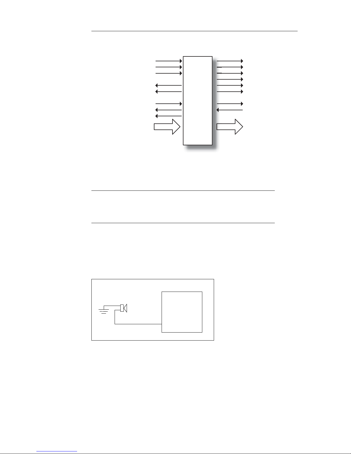
IQAN-MD3 . . . . . . . . . . . . . . . . . . . . . . . . . . . . . . . . . . . . . . . . . . . . . . . . . . . 5
System overview . . . . . . . . . . . . . . . . . . . . . . . . . . . . . . . . . . . . . . . . . . . 5
I/O overview . . . . . . . . . . . . . . . . . . . . . . . . . . . . . . . . . . . . . . . . . . . . . . 6
CAN related functions . . . . . . . . . . . . . . . . . . . . . . . . . . . . . . . . . . . . . . . . . . 6
Diagnostics . . . . . . . . . . . . . . . . . . . . . . . . . . . . . . . . . . . . . . . . . . . . . . . 7
Communication . . . . . . . . . . . . . . . . . . . . . . . . . . . . . . . . . . . . . . . . . . . . 7
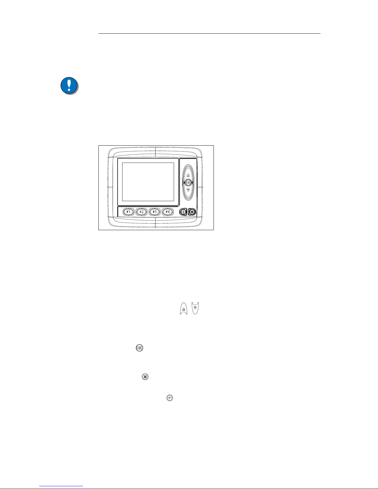
HMI (human machine interface) . . . . . . . . . . . . . . . . . . . . . . . . . . . . . . . . . . . 7
Features . . . . . . . . . . . . . . . . . . . . . . . . . . . . . . . . . . . . . . . . . . . . . . . . . 7
Display . . . . . . . . . . . . . . . . . . . . . . . . . . . . . . . . . . . . . . . . . . . . . . . . . . 8
Environment Specification . . . . . . . . . . . . . . . . . . . . . . . . . . . . . . . . . . . . 8
IQAN-MD3 menu system . . . . . . . . . . . . . . . . . . . . . . . . . . . . . . . . . . . . . . . . 9
Overview . . . . . . . . . . . . . . . . . . . . . . . . . . . . . . . . . . . . . . . . . . . . . . . . . 9
System information . . . . . . . . . . . . . . . . . . . . . . . . . . . . . . . . . . . . . . . . . 9
Preferences . . . . . . . . . . . . . . . . . . . . . . . . . . . . . . . . . . . . . . . . . . . . . . 10
Measuring . . . . . . . . . . . . . . . . . . . . . . . . . . . . . . . . . . . . . . . . . . . . . . . 10
Adjusting . . . . . . . . . . . . . . . . . . . . . . . . . . . . . . . . . . . . . . . . . . . . . . . . 11
Internal Diagnostics . . . . . . . . . . . . . . . . . . . . . . . . . . . . . . . . . . . . . . . . . . . 13
Safe mode . . . . . . . . . . . . . . . . . . . . . . . . . . . . . . . . . . . . . . . . . . . . . . . . . . 13
4 Safety . . . . . . . . . . . . . . . . . . . . . . . . . . . . . . . . . . . . . . . . . . . . . . . . . . . . . . . . 14
Internal diagnostics . . . . . . . . . . . . . . . . . . . . . . . . . . . . . . . . . . . . . . . . . . . 14
CAN-bus interruption . . . . . . . . . . . . . . . . . . . . . . . . . . . . . . . . . . . . . . . . . . 14
Current check . . . . . . . . . . . . . . . . . . . . . . . . . . . . . . . . . . . . . . . . . . . . . . . . 14
Emergency stop . . . . . . . . . . . . . . . . . . . . . . . . . . . . . . . . . . . . . . . . . . . . . . 14
5 Mounting . . . . . . . . . . . . . . . . . . . . . . . . . . . . . . . . . . . . . . . . . . . . . . . . . . . . . 15
Mounting the unit . . . . . . . . . . . . . . . . . . . . . . . . . . . . . . . . . . . . . . . . . . . . . 15
Dashboard or panel assembly . . . . . . . . . . . . . . . . . . . . . . . . . . . . . . . 15
Mounting considerations . . . . . . . . . . . . . . . . . . . . . . . . . . . . . . . . . . . . 15
6 Installation . . . . . . . . . . . . . . . . . . . . . . . . . . . . . . . . . . . . . . . . . . . . . . . . . . . . 17
Connectors C1 and C2 . . . . . . . . . . . . . . . . . . . . . . . . . . . . . . . . . . . . . . . . . 17
Connector pin assignments . . . . . . . . . . . . . . . . . . . . . . . . . . . . . . . . . . . . . 18
Supply voltage . . . . . . . . . . . . . . . . . . . . . . . . . . . . . . . . . . . . . . . . . . . . . . . 19
Emergency stop . . . . . . . . . . . . . . . . . . . . . . . . . . . . . . . . . . . . . . . . . . 19
Connecting of Supply Voltage . . . . . . . . . . . . . . . . . . . . . . . . . . . . . . . . 19
Polarity reversal . . . . . . . . . . . . . . . . . . . . . . . . . . . . . . . . . . . . . . . . . . 19
Addressing . . . . . . . . . . . . . . . . . . . . . . . . . . . . . . . . . . . . . . . . . . . . . . . . . . 20
IQAN-MD3 use of an ID-Tag . . . . . . . . . . . . . . . . . . . . . . . . . . . . . . . . . 20
Diagnostic interfaces . . . . . . . . . . . . . . . . . . . . . . . . . . . . . . . . . . . . . . . . . . 21
CAN diagnostics connection . . . . . . . . . . . . . . . . . . . . . . . . . . . . . . . . . 21
USB connection . . . . . . . . . . . . . . . . . . . . . . . . . . . . . . . . . . . . . . . . . . 22
USB and "ground loops" (differences in ground potential) . . . . . . . . . . 22
Reference voltage, VREF . . . . . . . . . . . . . . . . . . . . . . . . . . . . . . . . . . . . . . . 23
Voltage inputs . . . . . . . . . . . . . . . . . . . . . . . . . . . . . . . . . . . . . . . . . . . . . . . 24

iii
Contents
Instruction book, IQAN-MD3
Connecting sensors to the voltage inputs . . . . . . . . . . . . . . . . . . . . . . . 24
Connecting a 2-wire temperature sensor to voltage in . . . . . . . . . . . . . 25
Connecting switches to the voltage inputs . . . . . . . . . . . . . . . . . . . . . . 25
Connecting switches to the voltage inputs . . . . . . . . . . . . . . . . . . . . . . 26
7 Start-up . . . . . . . . . . . . . . . . . . . . . . . . . . . . . . . . . . . . . . . . . . . . . . . . . . . . . . . 27
Start-up procedures . . . . . . . . . . . . . . . . . . . . . . . . . . . . . . . . . . . . . . . . . . . 27
Starting the control system . . . . . . . . . . . . . . . . . . . . . . . . . . . . . . . . . . 27
Prepare for system start . . . . . . . . . . . . . . . . . . . . . . . . . . . . . . . . . . . . 27
Start the system . . . . . . . . . . . . . . . . . . . . . . . . . . . . . . . . . . . . . . . . . . 27
Appendix A . . . . . . . . . . . . . . . . . . . . . . . . . . . . . . . . . . . . . . . . . . . . . . . . . . . 28
IQAN-MD3 Technical Overview . . . . . . . . . . . . . . . . . . . . . . . . . . . . . . . . . . 28
Absolute Maximum Ratings . . . . . . . . . . . . . . . . . . . . . . . . . . . . . . . . . 28
Environmental ratings . . . . . . . . . . . . . . . . . . . . . . . . . . . . . . . . . . . . . . 28
Recommended Operating Conditions . . . . . . . . . . . . . . . . . . . . . . . . . . 29
System . . . . . . . . . . . . . . . . . . . . . . . . . . . . . . . . . . . . . . . . . . . . . . . . . 29
I/O . . . . . . . . . . . . . . . . . . . . . . . . . . . . . . . . . . . . . . . . . . . . . . . . . . . . . 30
User interface . . . . . . . . . . . . . . . . . . . . . . . . . . . . . . . . . . . . . . . . . . . . 30
Appendix B . . . . . . . . . . . . . . . . . . . . . . . . . . . . . . . . . . . . . . . . . . . . . . . . . . . 31
Error messages and actions . . . . . . . . . . . . . . . . . . . . . . . . . . . . . . . . . . . . . 31
Failure Modes . . . . . . . . . . . . . . . . . . . . . . . . . . . . . . . . . . . . . . . . . . . . . . . . 31
Failure modes for CAN interface . . . . . . . . . . . . . . . . . . . . . . . . . . . . . . 31
Failure modes for VREF . . . . . . . . . . . . . . . . . . . . . . . . . . . . . . . . . . . . 32
Failure modes for VIN . . . . . . . . . . . . . . . . . . . . . . . . . . . . . . . . . . . . . . 32
Failure modes for DIN . . . . . . . . . . . . . . . . . . . . . . . . . . . . . . . . . . . . . . 32
Appendix C . . . . . . . . . . . . . . . . . . . . . . . . . . . . . . . . . . . . . . . . . . . . . . . . . . . 33
Dimensioning of the IQAN-MD3 module . . . . . . . . . . . . . . . . . . . . . . . . . . . 33

1
Warnings
1 Introduction
Instruction book, IQAN
1 Introduction
These instructions are to be used as a reference tool for the vehicle manufacturer’s
design, production, and service personnel.
The user of these instructions should have basic knowledge in the handling of
electronic equipment.
Warnings
Sections marked with a symbol in the left margin, must be read and understood by
everyone using the system, carrying out service work, or making changes to hardware
and software.
The different symbols used in this manual are defined below.
WARNING
Sections labeled WARNING with a caution symbol in the left margin, indicate that a
hazardous situation exists. We use warnings, marked with the warning symbol, in two
ways.
• As a strong recommendation about work practices when using the product in the
machine (e.g. routines when updating an application). This use is common to the
term 'hazardous situation', that a person is exposed to a hazard.
• As a way of pointing out important information for the machine designer that in
some way relates to safety. This includes the design of the physical machine, and
also the application program being developed for the control system.
Not all document sections that contain information about safety are marked with a
warning symbol (there would be warnings everywhere). Failure to comply with the
recommendations can cause unintentional, and unexpected behavior of the control
system. This can potentially cause death, serious injury or property damage.
NOTICE
Sections labeled NOTICE with a notice symbol in the left margin, indicate there is
important information about the product. Ignoring this could result in less than optimal
performance, or damage to the product.
Contact the manufacturer if there is anything you are not sure about or if you have any
questions regarding the product and its handling or maintenance.
The term "manufacturer" refers to Parker Hannifin Corporation.

2
Overview of relevant documentation
1 Introduction
Instruction book, IQAN
Overview of relevant documentation
The following publications are relevant for users of this product.
The main documentation contains information that is not found elsewhere.
The additional documentation contains product information in a compact format, for
details on the information found in those documents, consult this manual.
The IQAN module documentation system.
Compact
Documentation
Main
Documentation
IQANdesign/
IQANrun
User Manuals
IQAN module
Instruction Book
HY33-8nnn-IB
IQAN module
Catalogue Datasheet
HY33-8nnn
IQAN module
Installation Sheet
HY33-8nnn-IS
IQAN module
Electrical Schematic
HY33-8nnn-ES
Mounting and Maintenance
Instruction Book
HY33-8327-IB

3
Read This
2 Precautions
Instruction book, IQAN
2 Precautions
Work on the hydraulics control electronics may only be carried out by trained
personnel who are well-acquainted with the control system, the machine and its safety
regulations.
WARNING
Make sure that you have sufficient knowledge before designing, modifiying or
servicing the control system.
Read the relevant sections of this document before conducting any work on the control
system.
WARNING
This product is not field repairable.
NOTICE
As much as possible of the welding work on the chassis should be done before the
installation of the system. If welding has to be done afterwards, the electrical
connections on the system must be disconnected from other equipment. The negative
cable must always be disconnected from the battery before disconnecting the positive
cable. The ground wire of the welder shall be positioned as close as possible to the
place of the welding. The cables on the welding unit shall never be placed near the
electrical wires of the control system.
Read This
Design of control system
WARNING
Risk of injury may be introduced by design of control system!
This product is designed to control hydraulic outputs. The control application must be
designed using basic safety principles so that unintentional movement is avoided.
The machine must be equipped with an emergency stop that stops all movement. Please
refer to section "Supply voltage".
Before you start
Read this document.
Read the IQANdesign software user manual section on 'application safety'.

4
Read This
2 Precautions
Instruction book, IQAN
Start-up, maintenance, and diagnostics
For all personnel carrying out installation, commissioning, maintenance or
troubleshooting.
WARNING
Work on the hydraulics control electronics may only be carried out by trained
personnel who are well-acquainted with the control system, the machine and its safety
regulations.
Before you start,
Read section "Start-up".
Additional information for service
Mounting and maintenance instruction book.
Additional information for diagnosing the system
Read section "System diagnostics", and see "Appendix B", in this document.
Use the IQANrun software user manual as a reference.

5
IQAN-MD3
3 Product description
Instruction book, IQAN- MD3
3 Product description
IQAN-MD3
IQAN-MD3 is a combined display and bus master capable of running applications
created by IQANdesign. Built on a 32-bit platform the unit has large computational
power and is capable of controlling large applications.
The IQAN-MD3 module.
System overview
The master module, IQAN-MD3, is the central unit in the system, or in the case of a
multi-master system, one of the central units. IQAN-MD3 has three CAN buses. The
CAN buses support ICP and are able to control IQAN expansion units. SAE J1939 and
Generic CAN protocols are also supported on the CAN buses and gives the possibility
to interface to 3rd party units. It is recommended to keep one CAN bus available (no
traffic or minimal traffic) for diagnostic purposes.
"Soft" function buttons and control buttons in combination with a graphical display
makes system feedback with user interaction possible. The display in the module has
very high optical performance across a wide operating temperature range and over a
wide range of ambient light.
IQAN-MD3 has voltage and digital inputs that are designed to be flexibly configured
using IQANdesign software. The unit also has a low power digital output.
All I/O are EMI filtered and protected against short circuit to -BAT and +BAT.
A typical IQAN-MD3 system
Levers and sensors IQAN-MD3
Expansion units

6
CAN related functions
3 Product description
Instruction book, IQAN- MD3
I/O overview
Inputs/Outputs
The IQAN-MD3 module has seven (7) voltage inputs VIN-A thru VIN-G for
connection of 0-5 Vdc signals. These inputs can be configured as digital inputs for
reading switches. Voltage inputs and digital inputs share positions, see below.
There is a digital output, DOUT-A, on IQAN-MD3 that may be activated when there is
an error message for the system, such as a short-circuit and input or output interruption.
By connecting the digital output to a warning lamp or audio signal, the driver is alerted
that an error message has been given.
Connect the alarm (audio signal) between pin C2:12 and ground (the battery’s negative
pole). See the illustration below. An active output gives battery voltage (11-32 Vdc) to
the pin. The maximum load is 200 mA.
Connection of DOUT as an alarm output.
CAN related functions
The IQAN-MD3 uses three CAN-buses (CAN = Controller Area Network) to
communicate with IQAN expansion modules, other systems and diagnostics.
(7) Voltage inputs VIN-A, VIN-B, VIN-C, VIN-D.....VIN-G
or
(7) Digital inputs DIN-A, DIN-B, DIN-C, DIN-D...... DIN-G
+BAT CAN-H
CAN-L
PORT 1
-BAT
+VREF
-VREF
PORT 0
CAN-H
CAN-L
+RTC
RS232-DATA IN
RS232-DATA OUT
RS232-READY
MD3
USB-D+
USB-D-
CAN-H/Diag
CAN-L/Diag
IQAN-MD3
DOUT

7
HMI (human machine interface)
3 Product description
Instruction book, IQAN- MD3
Diagnostics
Any of the IQAN-MD3 CAN buses may be dedicated for diagnostic purposes. This
function is available when using IQANdesign 2.0 version or higher.
NOTICE
It is recommended to have one CAN bus dedicated for diagnostic purposes.
Communication
The IQAN-MD3 has one RS232 port for remote diagnostics via ’dial-up’ modem
communication and one USB port for connection with a PC.
HMI (human machine interface)
IQAN-MD3 front panel HMI.
Features
IQAN-MD3 has a 3.5" transflective TFT color display, 320x240 pixels for reading
system information. The front of IQAN-MD3 consists of a control panel with a display
and nine buttons.
• F1 thru F4 function buttons.
Programmable ’softkeys’ that can be configured by IQANdesign software to bring
up a display page, bring up an adjustment group or act as a virtual input.
• Up and down arrow buttons , .
Navigation buttons that are used to scroll thru selections on a menu page. May be
configured by IQANdesign software to bring up a display page, bring up an
adjustment group or act as a virtual input.
• OK button .
Pushing this button equals ’enter’. Saves the value or confirms the selection you
have made.
• Menu button .
Always brings up the Menu page. It is not programmable.
• ’Esc’ or BACK button .
Returns you to the previous display page. May be configured by IQANdesign
software to bring up a display page, bring up an adjustment group or act as a virtual
input.

8
HMI (human machine interface)
3 Product description
Instruction book, IQAN- MD3
Display
Brightness
The brightness is easily adjusted by pressing the ’menu’ button and following the
prompts to the backlight settings section.
Burn-in
The IQAN-MD3 TFT display, like other computer screens can have a ghost picture
occur if a static image is left on the display for extended periods of time. For the best
viewing over the life of the product we recommend using the screensaver functionality.
NOTICE
To avoid burn-in, use the screensaver on the display.
Maintenance
The 3.5" transflective display is a high quality viewing interface and reasonable care
should be taken to maintain it.
The display can be cleaned with an LCD cleaning solution found in many stores. Use a
lightly dampened lint-free, non-abrasive cloth when cleaning the display.
NOTICE
To avoid scratches, do not wipe or clean a dry display.
Polarization
The MD3 screen has polarizers, the TFT is defined by its manufacturer as portrait
mode, but we have tilted it to have a landscape mode display. When wearing polarized
sunglasses, the effect is for the screen to be unreadable due to the conflicting
polarizations. This is easily solved by applying a film to the display. One type of film
that is proven to work is NuShield DayVue anti-reflective overlay film.
Environment Specification
IQAN-MD3 is a hardened module suitable for outdoor use. However, concentrating
cleaning jets on the control surface of the IQAN-MD3 can cause a degradation of the
finishing and should be avoided.
NOTICE
To keep the unit’s buttons looking their best, do not blast the control surface with
cleaning jets.
Back of unit
If the rear surface of the IQAN-MD3 unit is exposed and will be subjected to high
pressure steam cleaning, care should be taken around the connector assemblies. The
Deutsch DTM connectors are IP67 rated which is suitable for any type of outdoor
conditions. However, concentrating the cleaning jets on the connectors of the IQAN-
MD3 can cause damage to the connector seals or wire insulation and should be
avoided. Use of shielding is recommended to block high pressure cleaning jets, if the
rear of the unit is exposed.
NOTICE
To avoid damaging the connector seals or wire insulation, do not blast the connectors
with cleaning jets.

9
IQAN-MD3 menu system
3 Product description
Instruction book, IQAN- MD3
IQAN-MD3 menu system
The IQAN-MD3 has an easy to use graphical user interface and menu system. In the
display’s menu system, you get access to information and settings concerning the
IQAN system.
Menu navigation flowchart.
Overview
The menu system is an easy to use set of pages in the IQAN-MD3 that allow you to see
module information and logs, set preferences, measure system I/O or adjust
parameters.
All of this is done using the control and function buttons on the face of the IQAN-
MD3. To begin, go to the main menu page by simply pressing the ’menu’ button (three
horizontal lines). You may return to the operating display at any time by pressing the
menu button again.
Main menu page.
System information
To see information about your system press the button on the main menu page under
the ’Info’ icon, F4. This will bring up the information page which displays the loaded
application name, the last person who performed an edit and when the edit was done.
Operating
display page
Menu page
Adjustment
page
Measurement
page
Preferences
page
Information
page
From any page:
Press menu to quit or
press escape to go back
to the previous page
Press menu button
Select
adjust group
Select
measure group
Select
display, time
or language
Select
module,
modem or log
Change
settings
View
information
Press a function button
Select function
or channel
Select raw or
scaled value
Change
parameters or
reset to defaults
View
measurements
menu button
Main
Measure
Adjust Preferences Info

10
IQAN-MD3 menu system
3 Product description
Instruction book, IQAN- MD3
Other button options now appear for the function buttons that allow you to view
information about modules, modem or logs. To return to the previous (main menu)
page you can press the ’escape’ button. The ’escape’ button always takes you back to
the previous page. If you have chosen to view information on any of the other pages
you are given the option to simply press the button under the ’Main’ icon, F1.
Information page.
Preferences
To set preferences for the IQAN-MD3 press the button on the main menu page under
the ’Preferences’ icon, F3. This will bring up the preferences page. Other button
options now appear for the function buttons that allow you to set preferences for the
display, date/time or language. To return to the previous (main menu) page you can
press the ’escape’ button. If you have chosen to view information on any of the other
pages you are given the option to simply press the button under the ’Main’ icon, F1.
Preferences page.
Measuring
If you would like to measure any channels using the IQAN-MD3 press the button on
the main menu page under the ’Measure’ icon, F2. This will bring up the measure page
that displays the measure groups that have been set up in IQANdesign. To select a
measure group you press the up or down buttons until it is highlighted and then press
’OK’. That takes you to a page where you may view the channels in the selected group.
Button F2 may now be used to toggle between raw values and scaled values for the
channels. To return to the measure page you can press the ’escape’ button. To return to
the main menu page, you are given the option to simply press the button under the
’Main’ icon, F1.
esc button
Main
Measure
Adjust Preferences Info
to go back
esc button
Main
Measure
Adjust Preferences Info
to go back

11
IQAN-MD3 menu system
3 Product description
Instruction book, IQAN- MD3
Measure page.
Adjusting
If you would like to adjust any channels using the IQAN-MD3 press the button on the
main menu page under the ’Adjust’ icon, F1. This will bring up the adjust page that
displays the adjustable groups that have been set up in IQANdesign. To select an
adjustable group you press the up or down buttons until it is highlighted and then press
’OK’. That will take you to the next page, where you may view the channels in the
selected group. If a lock icon, is next to the group in the list, then a pin code is
required to access that group. Press the up, down and OK buttons to enter the pin code
Adjust page.
Once you have selected a group, a list of the adjustable channels is displayed. You may
select a particular channel in the same way you selected the group, by using the up and
down buttons and pressing OK. To choose the plus or minus direction for adjusting, use
the appropriate function button F3 or F4. The current parameters for the highlighted
direction are displayed on the right side of the display window. When you have
highlighted the desired channel and direction, press OK.
press OK
Main
Measure
Adjust Preferences Info
to select
press OK
Main
Measure
Adjust Preferences Info
to select
lock icon

12
IQAN-MD3 menu system
3 Product description
Instruction book, IQAN- MD3
Adjust group page.
Adjusting a parameter
Now you are at the page where the actual adjustment is done. You may toggle through
the different parameters by pressing OK repeatedly. When the parameter you wish to
adjust is highlighted, you may change it by pressing the up and down buttons. The
displayed values change to give you feedback. At any time after adjustments have been
made, if you want to return to the default values of the application, you may press the
button under the ’Reset’ icon, F2. To return to the previous page you can press the
’escape’ button. To return to the main menu page, you are given the option to simply
press the button under the ’Main’ icon, F1.
Adjusting a parameter.
press OK
Main
Measure
Adjust Preferences Info
to select
press up and
Main
Measure
Adjust Preferences Info
down to adjust

13
Internal Diagnostics
3 Product description
Instruction book, IQAN- MD3
Internal Diagnostics
The IQAN-MD3 has a diagnostics page. This page can be useful for obtaining
diagnostic information. To view the test page, press the menu and escape buttons
simultaneously and hold during power up. To exit test mode, turn the unit off and
power up normally.
Accessing the diagnostics page.
Safe mode
If necessary, the IQAN-MD3 may be started in safe mode. When started in safe mode,
no application is loaded and nothing is running. The screen shows a default background
and a dialog box notifies the user that the unit is in safe mode. This can be useful for
installing an IQAN-MD3 with an unknown application in memory, when retrofitting of
new hydraulic components has occurred or if a user has somehow changed the
application in an unacceptable way. To start in safe mode, press the escape button and
hold during power up. In safe mode you can then upload a new application to the
IQAN-MD3. To exit safe mode, turn the unit off and power up normally.
menu button
esc button

8
Internal diagnostics
4 Safety
Instruction book, IQAN
4 Safety
Internal diagnostics
The module performs a number of self-checks that improve safety. Checks include
monitoring of voltage supplies, checksums on memory and a watchdog that monitors
software execution. The module is using a real time operating system which supervises
software execution.
If a critical error is detected, the module is stopped, with CAN-bus and outputs off.
CAN-bus interruption
The IQAN modules communicate on a CAN-bus. Both the master module and
expansion modules check for any interruptions in CAN-bus communication. If an error
occurs the master will use zero or an application defined error value for the module
inputs, and the module outputs will be off.
The error will be presented on the master/display module, if there is one, and with a
related blink code on the IQAN module status LEDs.
Current check
For the proportional outputs when used in current mode, a current check is performed.
If an error is detected, this will be indicated on the master module, and the output will
shut off.
The module can detect open-circuit, short-circuit to +BAT/-BAT or short-circuit to
other proportional output and return pins.
Emergency stop
WARNING
Risk of injury!
The emergency stop must disconnect the power supply to the module; do not connect
the emergency stop as a signal input only.
The emergency stop must be installed so that the risk of reverse feed of the module is
avoided, see section "Supply voltage".

15
Mounting the unit
5 Mounting
Instruction book, IQAN- MD3
5 Mounting
Mounting the unit
The IQAN-MD3 unit should be mounted according to the following instructions.
Dashboard or panel assembly
• When installing in a dash or panel the recommended panel thickness is 1.0 - 3.5
mm. Use PT40 screws to mount the unit
Mounting the IQAN-MD3.
NOTICE
Select the screw length so that the thread engagement in the unit is 8-11 mm.
• Less engagement and the screw may not hold.
• More engagement and the housing may be damaged.
Mounting considerations
NOTICE
IQAN-MD3 shall be positioned in the machine per the following instructions:
• The unit is designed for outdoor use. Position the unit in desired location and make
sure that it is not exposed to mechanical damage.
• The connectors on the reverse side of the unit should be accessible.
• Position the unit so there is no risk that the cabling can be folded, crushed, worn or
damaged in any way.
96
118
82
91
Mv-0.8-1.0 Nm
PT40 screw
ø4.5
R8.0 max

16
Mounting the unit
5 Mounting
Instruction book, IQAN- MD3
• Leave sufficient room behind the unit to insert connectors. Less than 75 mm
clearance will stress the cabling and distort the seals in the connectors. This can
cause the environmental specification not to be met.
Distance behind the unit.
NOTICE
Take careful consideration when positioning the unit.
• Position the unit so there is no risk to be exposed to external heat, e.g. from the
engine or heater.
• The best readability will be achieved by positioning the front face of the unit
directly towards the operator.
• Extended periods of exposure to direct sunlight can cause an internal temperature
exceeding 75°C which may cause permanent degradation of the LCD display.
NOTICE
Both of the connectors, C1 and C2, must be properly installed in the unit.
• If you leave a connector unplugged, the unit will not be sealed.
• If unused wire positions in a connector are not closed with the recommended plugs,
the unit will not be sealed.
75 mm
22 mm
48 mm

17
Connectors C1 and C2
6 Installation
Instruction book, IQAN- MD3
6 Installation
Connectors C1 and C2
NOTICE
No pin may be "double crimped". That means only one wire may be attached to any
given pin. Failure to follow this instruction will cause the module to not meet the
environmental specification.
Make "Y" connections or splices using weatherproof methods external to the IQAN-
MD3 connectors.
Connector kit Parker 20073081 C1 (DTM12 key A)
Housing, C1 Deutsch no. DTM06-12-SA
Pin type Deutsch no. 1062-20-0222
Wedge type Deutsch no. WM12S
Sealing plug Deutsch no. 0413-204-2005
C2 (DTM12 key B)
Housing, C2 Deutsch no. DTM06-12-SB
Pin type Deutsch no. 1062-20-0222
Wedge type Deutsch no. WM12S
Sealing plug Deutsch no. 0413-204-2005
Recommended
cable 0.75-1 mm2 (18 AWG)
5
4
3
2
1
12 11 10 987
6
11 10 987
6
54
32
1
12
+BAT CAN-H
CAN-L
PORT 1
-BAT
+VREF
-VREF
PORT 0
CAN-H
CAN-L
+RTC
RS232-DATA IN
RS232-DATA OUT
RS232-READY
MD3
USB-D+
USB-D-
CAN-H/Diag
CAN-L/Diag
Other manuals for IQAN-MD3
1
Table of contents
Other Parker Control System manuals