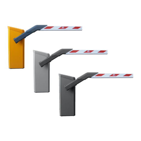
Magnetic Autocontrol MAGSTOP MBE35 User manual

Operation Instructions
MBE35_50 OPERATION MANUAL 2005_10 - 1 -
Operating Instructions
MAGSTOP Traffic Barrier
MBE35/50
Version 2005_10

Operation Instructions
MBE35_50 OPERATION MANUAL 2005_10 2
TABLE OF CONTENTS
1.0 SAFETY...........................................................................................................................................................4
1.1 SAFETY SYMBOLS USED IN THIS HANDBOOK................................................................................................................................4
1.2 GENERAL SAFETY INFORMATION.................................................................................................................................................. 5
1.3 INTENDED USE.............................................................................................................................................................................. 5
1.4 WARNING AND SAFETY SIGNAGE ................................................................................................................................................. 5
1.5 SAFETY REQUIREMENTS.............................................................................................................................................................. 6
1.6 OPERATIONAL SAFETY ................................................................................................................................................................. 7
1.7 TECHNICAL DEVELOPMENTS ........................................................................................................................................................ 8
1.8 WARRANTY................................................................................................................................................................................... 8
2.0 INSTALLATION ...................................................................................................................................................8
2.0 INSTALLATION ...................................................................................................................................................9
2.1 GUIDELINES FOR FOUNDATION .................................................................................................................................................... 9
2.1 MOUNTING THE HOUSING TO THE GROUND ............................................................................................................................... 10
3.0 OPERATING THE MBE* BARRIER GATE..........................................................................................................13
4.0 CONTROLLER...................................................................................................................................................14
4.1 GENERAL.................................................................................................................................................................................... 14
4.2 CONTROLLER INPUTS................................................................................................................................................................. 16
4.3 CONTROLLER OUTPUTS ............................................................................................................................................................. 18
4.4 OPERATING MODES AND ADDITIONAL FUNCTIONS ..................................................................................................................... 19
4.5 DIP SWITCH SETTINGS .............................................................................................................................................................. 20
4.6 OPERATING MODES ................................................................................................................................................................... 23
4.6.1 OPERATING MODE 1......................................................................................................................................................... 23
4.6.2 OPERATING MODE 2......................................................................................................................................................... 24
4.6.3 OPERATING MODE 3......................................................................................................................................................... 25
4.6.4 OPERATING MODE 4......................................................................................................................................................... 26
4.6.5 OPERATING MODE 5......................................................................................................................................................... 27
4.6.6 OPERATING MODE 6......................................................................................................................................................... 31
4.6.7 OPERATING MODE 7......................................................................................................................................................... 31
4.6.8 OPERATING MODE 8......................................................................................................................................................... 35
4.6.9 OPERATING MODE 9. ........................................................................................................................................................ 36
4.6.10 OPERATING MODE A..................................................................................................................................................... 40
4.6.11 OPERATING MODE B..................................................................................................................................................... 40
5.0 INSTALLING THE INDUCTION LOOPS..............................................................................................................44
5.1 GENERAL INDUCTION LOOP FUNCTIONALITY.............................................................................................................................. 44
5.2 LOOP INDUCTANCE .................................................................................................................................................................... 44
5.2.1 INDUCTANCE ........................................................................................................................................................................... 44
5.2.2 VEHICLE DETECTION ............................................................................................................................................................... 45
5.2.3 WIRE TURNS REQUIRED FOR LOOPS ...................................................................................................................................... 45
5.2.4 LOOP INDUCTANCE CALCULATIONS ........................................................................................................................................ 46
5.3 LOOP DETECTOR SENSITIVITY................................................................................................................................................... 47
5.4 INSTALLING AN INDUCTION LOOP............................................................................................................................................... 47

Operation Instructions
MBE35_50 OPERATION MANUAL 2005_10 - 3 -
5.4.1 USAGE OF PRE-MANUFACTURED LOOPS............................................................................................................................... 47
5.4.2 SELF-MADE LOOPS ................................................................................................................................................................ 47
5.4.3 LOOP LEAD WIRES ................................................................................................................................................................. 48
5.4.4 HOW DEEP SHOULD THE LOOP WIRES BE INSTALLED?.......................................................................................................... 49
5.4.5 LOOP DISTANCE FROM OBJECTS:........................................................................................................................................... 50
6.0 COMMISSIONING.............................................................................................................................................. 51
6.1 COMMISSIONING PROCEDURE ................................................................................................................................................... 51
6.3 STANDARD CONFIGURATION:.................................................................................................................................................... 51
7.0 BARRIER ARM SUPPORT ............................................................................................................................................................ 52
7.1 PENDULUM SUPPORT................................................................................................................................................................. 52
7.2 SUPPORT POST ......................................................................................................................................................................... 52
8.0 ARTICULATED GATE ARMS............................................................................................................................. 54
9.0 TECHNICAL DATA ............................................................................................................................................ 55
9.1 MAGSTOP BARRIERS.............................................................................................................................................................. 55
9.2 CONTROLLER ........................................................................................................................ERROR!BOOKMARK NOT DEFINED.
10. MAINTENANCE ................................................................................................................................................ 55
10.1 CHANGING THE RUBBER END STOP ....................................................................................................................................... 55
10.2 CHECKING THE EXTERIOR OF CABINET .................................................................................................................................. 55
10.3 CHECK THE BARRIER ARM AND THE ATTACHMENT KIT ............................................................................................................ 56
10.4 CHECKING THE LOOP DETECTORS AND LOOP WIRES............................................................................................................ 56
10.5 CHECK SAFETY SIGNAGE......................................................................................................................................................... 56
10.6 MAINTENANCE SERVICE RECORD........................................................................................................................................... 57

Operation Instructions
MBE35_50 OPERATION MANUAL 2005_10 4
1.0 Safety
1.1 Safety symbols used in this handbook
The following symbols are used in this operating instruction to indicate potential risks
and other safety information.
☞
Caution!
This symbol is used in this manual to designate those actions or states which
represent a potential hazard to petestrian, personal, property and
equipment. Please read these instructions very carefully.
Note!
This symbol is used in this manual to designate useful information for the
operator.
Warning!
This symbol is used in this manual to warn installer for potential harm. Please
read these instructions very carefully.

Operation Instructions
MBE35_50 OPERATION MANUAL 2005_10 - 5 -
1.2 General safety information
The MAGSTOP barrier system has been designed, built and tested using state-of-the-
art technology and left our factory only after passing stringent safety and reliability
criteria. Nevertheless, the barrier system can represent a risk to persons and property
if it is not installed and operated correctly. These operating instructions must therefore
be read in their entirety and all safety information contained therein must be complied
with.
The manufacturer shall refuse to accept liability and shall withdraw warranty if this
barrier system is used incorrectly or is used for a purpose for which it was not
intended.
1.3 Intended use
The MAGSTOP MBE 35/50 barriers are designed to control vehicular (see
pictogram below) access and exits to car parks, car parking garages, access
control applications and highways.
The MAGTRONIC control units have been specially designed for controlling Magnetic
barriers.
Any other use of these barrier systems is not permitted.
Modifications or changes to the barrier or to the control modules are prohibited.
Only original Magnetic spare parts and accessories shall be used.
1.4 Warning and safety signage
The Magnetic Automation Corp. MIB barriers come with two (2) safety-warning labels
(see Figure 1 above) that must be applied to the barrier housing so it can easily be
seen when a pedestrian, bicycle users, or motorized vehicle uses the lane. Magnetic
Automation Corp. requires that you use universally identifiable pictograms in all
entrance/exit lanes, roadways, post, and walls. It is strongly recommended to paint a
“NO PEDESTRIAN” pictogram on the roadway immediately adjacent to the parking
barrier gate.
Figure 1

Operation Instructions
MBE35_50 OPERATION MANUAL 2005_10 6
1.5 Safety Requirements
-Use vibrant colors on parking equipment
-Always provide proper signage, both on the road way and on other equipment
-Maintain manufacturers warning stickers on gate housing and gate arms.
-Always require that sidewalks are parallel to entrance and exit lanes, or require
having pedestrian entrances on opposite side of vehicle entrance and exit.
IMPORTANT:
It is A MUST to have pedestrian sidewalks installed parallel to entrance and exit lanes
or to have pedestrian walkways on the opposite sides of the facility away of vehicle
traffic. It is also necessary to enforce that pedestrian are using those walkways and
do not enter or leave the parking facility on vehicle traffic lanes.
NOTE: NOT COMPLYANCE WITH THE ABOVE SAFETY REQUIREMENTS
(Chapter 1.3 and 1.4) SHALL VOID ANY MANUFACTURERS LIABILITY!

Operation Instructions
MBE35_50 OPERATION MANUAL 2005_10 - 7 -
1.6 Operational safety
A safe clearance distance of at least 2 ft (24 inch) must be provided between
the tip of the barrier boom and the closest solid obstacle (building, wall, fence
etc.).
Any activity in the entrance and exit lanes should be monitored to ensure a safe
operation when opening or closing the barrier gates or to prevent altering or
vandalism to the equipment from unauthorized persons.
The motion of the barrier boom must be directly observable by the person operating
the barrier.
While the barrier boom is in motion, no pedestrian and no vehicle shall be in the
immediate vicinity of the barrier.
The assembly and installation instructions must be complied with in their entirety.
Any alterations must have received prior confirmation from Magnetic Automation
Corp.
Barrier booms longer than 14 ft require either a pendulum support or a supporting
pillar.
Only certified and trained electrical technicians may perform any electrical
connections, wiring work or exchange of components.
Before installing or maintaining the equipment the main power must be disconnected.

Operation Instructions
MBE35_50 OPERATION MANUAL 2005_10 8
1.7 Technical developments
The manufacturer reserves the right to modify, without prior notice, the technical
specifications in order to accommodate the latest technical developments. Magnetic
Automation Corp. will provide information on the status of existing operating
instructions and on any alterations and extensions that may be relevant.
1.8 Warranty
Magnetic provides a limited warranty on its barriers that covers all mechanical and
electrical components, but excludes parts subject to wear and tear, for a period of two
years from the date of first use or for a maximum of three years from the date on
which the system was delivered provided that the operating instructions have been
complied with, no unauthorized servicing of machine components has taken place,
and that no mechanical damage to the machines is evident.
Please refer to our Warranty Statement.
COPYRIGHT
2002 Magnetic Automation Corp.
All rights reserved. No part of this publication may be
reproduced, transmitted, transcribed, stored in a retrieval
system, or translated into any language in any form by any
means without the written permission of Magnetic
Automation Corp.
First Printing: 2002

Operation Instructions
MBE35_50 OPERATION MANUAL 2005_10 - 9 -
2.0 Installation
2.1 Guidelines for Foundation
To ensure that the equipment is solidly bolted to the ground under all operation
conditions, a foundation with the following dimensions shall be provided:
Depth of foundation: at least 3ft (frost-depth)
Base area of foundation: 19” x 23 ½”
The base of the foundation is 4” wider towards the vehicle passage side, than in other
section of the foundation (see Fig. S0225).
Fig. S0225
View of the foundation
1 Anchor bolts (4x)
2 Empty conduit for induction loop lead wire, dia. ½”
3 Conduit for power cables, dia. 1”
4 Conduit for control cables, dia. ½”
5 Concrete foundation
Conduit pipes (with different diameters for low and high voltage cables as per
Electrical code) must be installed to run the mains supply cable, the control cables
and the induction loop lead wires.
A reinforcing steel cage is absolutely essential for the stability of the foundation (see
Fig. S0102).
Abb. S0102
Steel reinforcement for
The concrete foundation
5 x ∅3/8”/17 ½” x 17 ½” St III
3 x ∅½”/ 29” x 16” St III
1
2
3
4
5
31
1/2
S0225
Foundation at
frost-line depth 3’
Concrete
foundation
PC 250
1 Conduit 1/2” for loop lead wires
1 Conduit 3/4” for power supply
must be extended and connected
to junction box
1 Conduit 1/2”” for control

Operation Instructions
MBE35_50 OPERATION MANUAL 2005_10 10
The foundation shall be constructed with at least 2500 PSI grade concrete. The
mounting surface must be leveled to insure a solid base for the barrier gate.
Once the concrete has set to an adequate hardness, the holes for the anchor bolts
can be drilled using the dimensions shown in Fig. S0112 as a guide. Magnetic
Automation Corp. recommends using ∅3/8” anchor bolts. Please refer to the anchor
bolt manufacturers installation requirements.
2.1 Mounting the housing to the ground
To mount the barrier gate on the concrete surface, follow the instructions below.
1. Carefully remove the gate from its shipping crate.
2. Open the barrier door
3. Place the gate on the desired position on the curb but leave 6”-12” distance from
the front of the housing to the curb line.
4. Place the gate so that the gate arm flange faces the opposite direction of traffic.
Please refer to the figure below and compare the Packing list to assure the
correct flange position (example: MBE35R-C100 = RH, MBE35L-C100 = LH).
5. Using a marker, follow the outside and inside contours to the concrete.
6. Remove barrier gate.
7"
7.5"
14"
12
4 x Mounting Holes
Housing
S0112
MBE
MBE

Operation Instructions
MBE35_50 OPERATION MANUAL 2005_10 - 11 -
7. Using a pencil, mark the location of the mounting holes on the concrete. (See fig.
S0112 for dimensions).
8. Drill all four mounting holes and insert the bolts. (Please refer to anchor bolt
manufacturers installation specifications). Make sure that the bolts stand up at
least 2 inches above the concrete surface.
9. Place the gate on top of the previous marked area.
10. Using the supplied U-channel (in accessory box) secure the gate to the concrete
(see Fig. S0106).
1 barrier housing
2 nut
3 lock washer
4 small flat washer
5 large flat washers
6 anchor bolt
7 U-rail
8 concrete foundation
1
2
3
4
5
6
7
8
S0106
Abb,S0106
Mounting the barrier housing to the
foundation
7"
7.5"
14"
12
4 x Mounting Holes
Housing
S0112

Operation Instructions
MBE35_50 OPERATION MANUAL 2005_10 12
11. Attach the field wiring to the proper terminals at the main power board. See
Drawing S0113 below. Make certain that the main circuit breaker is switched
OFF. Connect all electrical wiring exactly as directed in the Connection Diagram.
12. Attach the gate arm to the flange using the boom attachment kit (in accessory
box). Please refer to drawing below.
Fig
f
S0113
Field wiring diagram
PENL1
125V, 5A max.
LINE
Neutral
Ground
PENL1
Neutral
115 VAC, 60Hz,
5A max. Ground

Operation Instructions
MBE35_50 OPERATION MANUAL 2005_10 - 13 -
Notice:
With all MIB35 barriers 8mm Nylon hex nuts are provided to mount the gate arm to
the flange. This break away feature is only available for gate arms up to 12 ft. For
barrier arm length exceeding 12 ft it is not recommended to use any material other
then the provided 8mm steel hex nuts. Due to age deterioration (UV radiation), the
plastic nuts must be replaced annually.
3.0 Operating the MBE* Barrier Gate
In automatic operation, the MBE* Barrier gate can be operated using following
devices:
-Ticket Spitters
-Vehicle Detectors
-Card Readers
-Coin and Token acceptors
-Radio Controllers
-Switches, Push buttons, and other devices.

Operation Instructions
MBE35_50 OPERATION MANUAL 2005_10 14
☞
4.0 Controller
4.1 General
The ECOLINE controller has been specially designed for use with MBE 35and MBE
50 barrier gates. It cannot be used with any other barrier type.
This controller enables the barrier to be operated manually or automatically. There are
11 standard functions to be selected for operating the barriers. These functions cover
all standard applications.
The controller has 6 Inputs and 4 outputs. The operating mode and special
functionality can be adjusted using the rotary switch and the DIP switch. The
controller also comes with a manual reset button to reset the controller after any
changes were made.
The connection of additional safety equipment for pedestrians is possible.
Besides the standard operating modes several special functions are additionally
integrated. These enable the operation of traffic lights. The storage of opening pulses
(Vent signal count) makes access control possible. After power failure, there are three
possibilities to restart the barrier: Manual reset, signal reset or automatically. For
safety reasons the manual reset function is factory-set. This means the barrier
remains open until the reset button at the control unit is pressed. The electrical
connections are made on labeled terminal blocks. The motor is driven by a TRIAC
output stage.
Selection of the operating mode and the special functions are done by a rotary
selector switch and DIP-Switches.
For the power supply of optional external devices, for example induction loop
detectors, 24VDC/0.5A is supplied.
The controller has 6 Inputs and 4 outputs. The operating mode and special
functionality can be adjusted using the rotary switch and the DIPswitch. The controller
also comes with a manual reset button to reset the controller after any changes were
made.
Note:

Operation Instructions
MBE35_50 OPERATION MANUAL 2005_10 - 15 -
Each in and output has a red LED- Indicator light to display which in- or output
is currently activated. Light on = in- output active; Light off = in- output not
active.

Operation Instructions
MBE35_50 OPERATION MANUAL 2005_10 16
Note:
IN5 (external safety input) and IN4 (pedestrian safety input) must be made
(activated) in order for the barrier gate to operate. Standard factory setup is a
jumper wire to activate these inputs. When installing the safety devices a
normally closed contact must be used for both inputs and the factory wired
jumper must be removed. Attention: Remove the factory wired jumper only if
you use the input!
4.2 Controller Inputs
The MBE controller has 6 digital inputs (IN = Input). All inputs require a potential free
contact.
Following is a description of the individual inputs:
IN 1: Gate open input for operating modes 2,4 - B. Requires a potential free
normally open contact from an access control device, push button etc.
Higher priority than IN2 and IN3. As long as this input is made, the gate
will not close. In the dynamic operating modes 5, 6, 9, and A this input
starts the hold open time. In the operating modes 8, 9, A, and B this input
increments the vent count.
IN 2: Opening loop input. Requires a potential free normally open contact from an
inductive opening loop. The open hold time will not be set in any of the
modes.
IN 3: Gate close input. Requires a potential free a normally open contact. This
input will close the gate as long as none of the safety inputs IN4 and IN5 or
IN1 is activated.
IN 4: Pedestrian safety input. Used for safety edges or photo beams.
Requires a potential free normally closed contact. If the safety device
detects a pedestrian while closing it will reopen the barrier and stay up for
5sec. If the gate is up while a pedestrian or object is detected at IN4 it will
not close until the safety zone is cleared. This input can be disabled with an
optional limit switch.
IN 5: Vehicle safety/closing device input. Used for inductive loops and photo
beams. For example safety/closing inductive loop detector.
Requires a potential free normally closed contact. If the safety device
detects a vehicle while closing it will reopen the barrier and stay open until
the vehicle leaves the detection zone. If the gate is up while a vehicle or
object is detected at IN5, it will not close until the safety zone is cleared.
This input is disabled when the gate arm is in the down position by the
down limit switch on IN6.
IN 6: Limit switch input. This limit switch is installed EX factory in all MBE35 and
50 barriers. It has following functionality:

Operation Instructions
MBE35_50 OPERATION MANUAL 2005_10 - 17 -
1. Disabling of safety/closing devices connected to IN5 when the gate is in
the down position.
2. The limit switch provides the controller logic with the information that the
gate is in the down position.
3. If the controller is setup for signal reset (see chapter 4.5 DIP Switch 2) it
uses the limit switch feedback to determine in what position the gate is
when the main power returns after it was off.
4. If a warning signal is used on output relay K 3 (see chapter 4.3 and 4.5)
the signal will stay on for 5sec. after the controller received the feedback
from this limit switch that it is in the down position.

Operation Instructions
MBE35_50 OPERATION MANUAL 2005_10 18
4.3 Controller outputs
The MBE controller has 4 relay outputs (K* = Output). The output relay contacts are
rated for 24 VDC/ 1A.
Following is a description of the individual outputs:
K 1: Depending on DIP switch 5 settings:
DIP switch 5 in off position: Motor drive indication. Relay is active as
soon as gate starts to come down.
DIPswitch 5 in ON position: Gate closed indication. Relay is active as
soon as the gate is in full closed position, depending on limit switch
settings.
This relay output, independent of the DIPswitch setting, will cycle
between on and off when a gate failure occurred or right after the power
is turned on. In this case pushing the RESET button will get the
controller in the operating mode.
K2: Depending on DIP-switch 6 settings.
DIPswitch 6 in off position: 500ms pulse signal when barrier is open and
a vehicle passed through the safety/closing device connected to IN5.
DIPswitch 6 in on position: 500ms pulse signal when the controller
received in input on IN1 gate open.
K3: Depending on DIP-switch 7 settings.
DIPswitch 7 in off position: This output is used to turn warning signals
(lights or horns) on prior to closing the barrier. For example turning on a
red light to alarm people that the gate will close soon. The light will turn
off after 5 seconds after the gate closed.
DIPswitch 7 in on position: This output is used to turn warning signals
(lights or horns) on prior to closing the barrier. For example turning on a
red light to alarm people that the gate will close soon. The light will
remain on as long as the gate is in the down position.
K4: Depending on DIP-switch 8 settings.
DIP switch 8 in off position: Universal error output. If red LED is on no
error. Gate failures reported are: run time error in case the end limit
switch is not activated when the gate is in the down position, controller
is waiting for a manual or signal reset, safety inputs IN4 and IN5 are
occupied longer than 3 minutes, in case of a power failure of the 24V or
5V supply.
DIPswitch 8 in ON position: same functionality as K3 (DIP switch 7 on).

Operation Instructions
MBE35_50 OPERATION MANUAL 2005_10 - 19 -
4.4 Operating modes and additional functions
The 11 operating modes can be set by turning the rotary switch to the desired position
(see chapter 4.6).
The additional function can be set by setting the DIP-Switches to a certain position
(see chapter 4.5).
Rotary switch for
Operating mode
selection
1 2 3 4 5 6 7 8
ON ON
DIP-Switch for additional function
selection

Operation Instructions
MBE35_50 OPERATION MANUAL 2005_10 20
4.5 DIP Switch settings
Additional functionality can be set by switching the DIP-switches 1-8 in certain
positions:
Dip Switch Function
1 OFF After return of power the gate moves to the up position
and a manual reset using the reset button is required
1 ON Activates the RESET functions of DIPswitch 2.
2 OFF Signal reset. When the gate was in the up position before
the power turned off, and still is after the power returned,
the gate will stay up and only pressing the reset button at
the controller, a down command, or passing of the safety-
closing device will reset the gate to go down. If the gate
was in the fully closed position (down limit switch
activated) before the power went off, and still is when the
power returned, the gate will remain in the down position
2 ON Auto reset. The gate will close immediately after the
power is restored as long there is no vehicle or
pedestrian (if IN4 is used) in the detection zone.
ATTENTION: If the power was restored while a vehicle
was on the induction safety loop any loop detector will
read this vehicle as part of the loop and will not detect the
vehicle when the gate comes down. This will cause the
gate to hit the vehicle!
3 OFF
and
4 OFF
In this switch setting there is no closing delay, i.e. the
gate closes immediately after a closing command was
given on IN3 or a vehicle passed through the safety
closing zone
3 ON
and
4 OFF
In this switch setting the closing delay time is set to 2
sec. When a closing command on IN3 was given or a
vehicle passed through the safety-closing zone the
closing delay timer will start and the gate will not close
until the timer is elapsed.
3 OFF
and
4 ON
In this switch setting the closing delay time is set to 5
sec. When a closing command on IN3 was given or a
vehicle passed through the safety-closing zone the
1 2 3 4 5 6 7 8
ON ON
This manual suits for next models
1
Table of contents
Other Magnetic Autocontrol Control System manuals
Popular Control System manuals by other brands

Anilam
Anilam 4200T Programming and operations manual

Rain Bird
Rain Bird ESP-LXD Installation & troubleshooting guide

SBC
SBC PCD3.M6880 user manual

ITW
ITW Simco-Ion Conveyostat Installation and operating instructions

Duro Dyne
Duro Dyne DuroZone RED-4 installation instructions

Vestil
Vestil PRAIL-102 quick start guide