Intelligent Charging LSU220A User manual

LSU220A : Load Support Unit
Operators Manual
Doc: DWG1063-08-R2 LSU220A Operators Manual.o t Page 1 of 16 Copyright Material of Intelligent Charging Limited © 2018
Printed On : 17/07/19
LSU220A
LOAD SUPPORT UNIT
OPERATORS MANUAL

LSU220A : Load Support Unit
Operators Manual
Table of ontents
1 MANUAL REVISION HISTORY....................................................................................................3
2 DESCRIPTION..........................................................................................................................4
3 INSTALLATION.........................................................................................................................5
3.1 POSITIONING THE EQUIPMENT..........................................................................................5
3.2 CONTROLS AND INDICATORS............................................................................................6
3.2.1 Fron panel.................................................................................................................6
3.2.2 Rear panel..................................................................................................................7
4 OPERATION.............................................................................................................................8
5 CALIBRATION.........................................................................................................................10
5.1 CHECKING PROCEDURE...................................................................................................11
5.1.1 Vol age valida ion......................................................................................................11
5.1.2 Curren valida ion......................................................................................................12
5.2 ADJUSTMENT PROCEDURE...............................................................................................12
5.2.1 Vol age adjus men ...................................................................................................12
5.2.2 Curren adjus men ...................................................................................................12
6 SPECIFICATIONS....................................................................................................................14
7 PRODUCT DISPOSAL INSTRUCTIONS.......................................................................................15
8 PRODUCT WARRANTY.............................................................................................................16
Doc: DWG1063-08-R2 LSU220A Operators Manual.o t Page 2 of 16 Copyright Material of Intelligent Charging Limited © 2018
Printed On : 17/07/19

LSU220A : Load Support Unit
Operators Manual
1 MANUAL REVISION HISTORY
Rev Date Description
1 10-03-2015 First write.
2 21-07-2015 Formatting changes.
Doc: DWG1063-08-R2 LSU220A Operators Manual.o t Page 3 of 16 Copyright Material of Intelligent Charging Limited © 2018
Printed On : 17/07/19

LSU220A : Load Support Unit
Operators Manual
2 DES RIPTION
The LSU220A is a general purpose load suppor uni designed o ac as a permanen power
supply o main ain backup ba ery sys ems whils al erna ive sources of power are ei her
imprac ical or unavailable, such as running diesel engines during main enance programs.
The LSU220A can suppor bo h 12V and 24V sys ems by simple manual vol age adjus men ,
wi h a curren capaci y of up o 220A amperes.
7 segmen display con inuously shows bo h se vol age and curren draw.
Vol age ou pu can be rimmed in small s eps during opera ion o offse cable drops and/or
varia ions in demand which can crea e excessive demand on he backup ba eries.
Ou pu is simply enabled or disabled by run and s op bu ons.
In ernal variable speed fans are employed o ensure he LSU220A opera es a a reasonable
empera ure.
The LSU220A is designed o opera e from a s andard s ar connec ed 415V hree phase supply
in a L1 + L2 + L3 + N + E configura ion.
The LSU220A has a simple user calibra ion procedure o ensure he displays show accura e
readings.
Doc: DWG1063-08-R2 LSU220A Operators Manual.o t Page 4 of 16 Copyright Material of Intelligent Charging Limited © 2018
Printed On : 17/07/19

LSU220A : Load Support Unit
Operators Manual
3 INSTALLATION
3.1 POSITIONING THE EQUIPMENT
The LSU220A should be moun ed on a level surface such as a workbench or s urdy shelf which
can suppor a weigh of a leas 30Kg.
The uni should be si ed so ha a leas 10cm of airspace is available all round he lef and op
of he uni and a leas 20cm on he righ hand side o allow free movemen of air required for
cooling.
10 cm 20 cm
10 cm
1 2
BACO
VOLTAGE CURRENT
OUTPUT STATE
OFF
OUTPUT TRIM
POWER
LSU220A
LOAD SUPPORT UNIT
ON
LOAD
RUNNING STOPPED
OUTPUT 27V 220A MAXIMUM
Direction of Airflow
The LSU220A is supplied fi ed wi h a hree phase L1 + L2 + L3 + N + E plug on 3m of lead.
200.00 mm
360.00 mm
Total Length 3.0m Approx
P lu g 3 P + N + E IP 4 4
The load is connec ed via an Anderson 350A connec or fi ed o he chassis. A 3m lead is
supplied fi ed a each end wi h ma ing Anderson 350A plugs. The cable has a cross sec ion of
50mm2 per conduc or. While opera ing he uni a very high curren s he leads should be laid
ou in such a manner as o aid cooling.
3.0m Approx
Doc: DWG1063-08-R2 LSU220A Operators Manual.o t Page 5 of 16 Copyright Material of Intelligent Charging Limited © 2018
Printed On : 17/07/19

LSU220A : Load Support Unit
Operators Manual
3.2 ONTROLS AND INDI ATORS
3.2.1 Front panel
A) Main inpu supply swi ch urn o posi ion “2” o opera e he uni .
B) Ou pu connec or Anderson 350A.
C) Off push bu on. Pressing his while he uni is running and providing ou pu power will
s op he ou pu power.
D) This indica or will be illumina ed when he uni is s opped and no ou pu ing power.
E) This indica or will be illumina ed when he uni is running and ou pu ing power.
F) ON push bu on. Pressing his when he uni is s opped will cause he uni o provide he
ou pu power.
G) Down push bu on. Pressing his while he uni is running and providing ou pu power
will cause he ou pu vol age o be reduced. Pressing his while he uni is s opped will
cause he display brigh ness o be reduced.
H) Up push bu on. Pressing his while he uni is running and providing ou pu power will
cause he ou pu vol age o be reduced. Pressing his while he uni is s opped will
cause he display brigh ness o be increased.
I) Vol age indica ion. While he uni is swi ched on i will show he vol age presen a he
ou pu erminals in 0.1V s eps.
J) When he uni is running and providing ou pu power i will show he number of amps
being provided in 1A s eps.
Doc: DWG1063-08-R2 LSU220A Operators Manual.o t Page 6 of 16 Copyright Material of Intelligent Charging Limited © 2018
Printed On : 17/07/19
1 2
BACO
VOLTAGE CURRENT
OUTPUT STATE
OFF
OUTPUT TRIM
POWER
LSU220A
LOAD SUPPORT UNIT
ON
LOAD
RUNNING STOPPED
OUTPUT 27V 220A MAXIMUM
H
G
FEDCB
A
IJ

LSU220A : Load Support Unit
Operators Manual
3.2.2 Rear panel
K) Power cord inle .
Doc: DWG1063-08-R2 LSU220A Operators Manual.o t Page 7 of 16 Copyright Material of Intelligent Charging Limited © 2018
Printed On : 17/07/19
SERIAL No:
INTELLIGENT CHARGING
CasC Systems Lt
For House, Dewing Roa ,
Rackheath In . Est. Norwich,
Norfolk, NR13 6PS, ENGLAND.
TEL: +44-1603-722770
FAX: +44-1603-722771
MAIL: sales@intelligent-chargingcom
HARGING
INTELLIGENT
FROM
MODEL :
P/N :
MADE IN ENGLAND
C A S C S Y S T E M S L T D
415V AC
THREE PHASE INPUT ONLY
CIRCUIT MUST BE PROTECTED BY 16A
FUSE OR BREAKER ON EACH PHASE
K

LSU220A : Load Support Unit
Operators Manual
4 OPERATION
efore connecting to the load for the first time the LSU220A has to be set to the
nominal voltage of the load system it is going to supply. The following steps must be
followed prior to connecting to the load.
Apply power to the LSU220A with load unconnected. Power switch rotated
clockwise to position 2.
Press the RUN button and check the output state RUN LED is lit GREEN and the
STOPPED LED is not lit.
The VOLTAGE display will show the value of output voltage that is currently set.
Use the OUTPUT TRIM pq push buttons to set the output voltage display to the
load voltage required. This setting will be remembered when power is removed.
Note if you press and hold either the pq push buttons the adjustment will be
continuous.
Press the stop button and check the RUN LED is not lit and the STOPPED LED is lit.
The voltage display will slowly reduce to zero, or will fall to zero very rapidly if the
load is connected.
At this point the load can be connected.
If any residual voltage is shown on the VOLTAGE display this will reduce very
rapidly to zero. If the load already has a voltage present, such as a battery
maintained system then the VOLTAGE display will show this value.
The following steps are followed upon equipment connection.
Press the START push button and verify the RUN LED is lit and the STOPPED LED
is not lit.
The VOLTAGE display will show the output voltage.
The CURRENT display will show the output amps being drawn from the unit.
When the output voltage is no longer required press the STOP push button.
At very high currents the voltage drop in the leads may not provide enough
voltage at the equipment.
To overcome this high voltage drop the output voltage can be trimmed by pressing
the OUTPUT TRIM pq push buttons to set the desired output. This setting will be
remembered when power is removed. Note if you press and hold either the pq
push buttons the adjustment will be continuous.
Doc: DWG1063-08-R2 LSU220A Operators Manual.o t Page 8 of 16 Copyright Material of Intelligent Charging Limited © 2018
Printed On : 17/07/19

LSU220A : Load Support Unit
Operators Manual
On battery maintained systems caution must be observed when using the trim
feature as not to overcharge the battery as high voltages will cause some of the
current to be passed to the battery.
After long term use a very high current it is wise to follow this procedure to enable
the unit to safely cool down prior to moving.
After pressing STOP to remove the output disconnect the load.
It will be noted that the fans will reduce to a low setting and then stop.
Press the START push button, the display will show the voltage that was set.
It will be noted that the fans will then start up again and run slowly while the PSU
units are cooled.
Once the fans have stopped it is safe to remove power from the unit by moving
the switch counter clockwise to position 1.
Doc: DWG1063-08-R2 LSU220A Operators Manual.o t Page 9 of 16 Copyright Material of Intelligent Charging Limited © 2018
Printed On : 17/07/19
LSU220A : Load Support Unit
Operators Manual
5 ALIBRATION
The LSU220A has two displays which show Voltage and Current. These are electronic
displays which will require regular checking for their accuracy. Intelligent Charging
recommends that the calibration check procedure is followed annually.
To calibrate the unit the following equipment will be required.
1.Calibrated voltmeter capable of reading 24V to one decimal place.
2.Calibrated ammeter capable of reading up to 200A to one significant digit, or a
calibrated ammeter shunt and millivoltmeter combination.
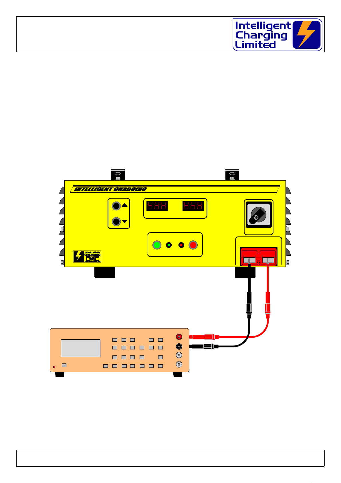
The equipment will need to be connected as shown in the following figures.
VOLTAGE MEASUREMENT
Doc: DWG1063-08-R2 LSU220A Operators Manual.o t Page 10 of 16 Copyright Material of Intelligent Charging Limited © 2018
Printed On : 17/07/19
1 2
BACO
VOLTAGE CURRENT
OUTPUT STATE
OFF
OUTPUT TRIM
POWER
LSU220A
LOAD SUPPORT UNIT
ON
LOAD
RUNNING STOPPED
OUTPUT 27V 220A MAXIMUM
1705 TRUE RMS PROGRAMMBLE MULTIMETER
+VE
COMMON
2A
10A
0.00V
0.00V
LSU220A : Load Support Unit
Operators Manual
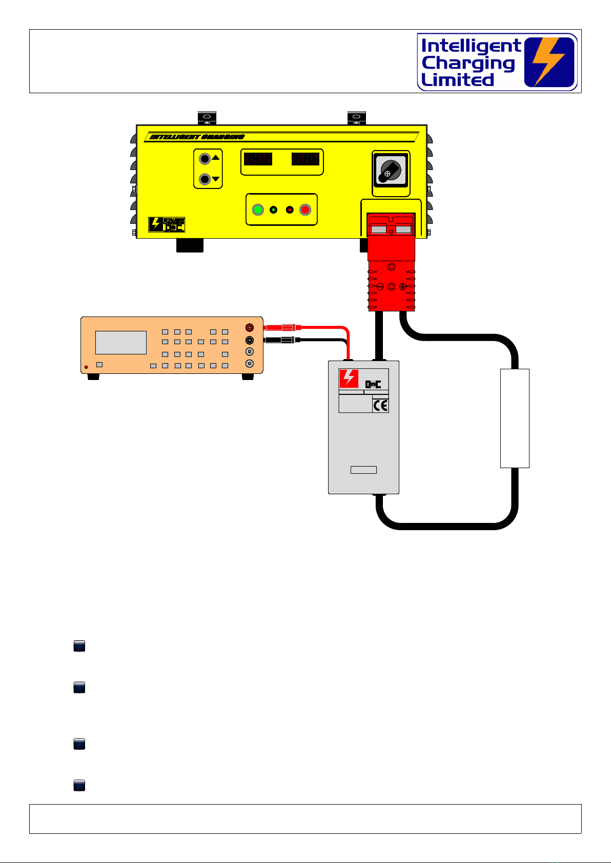
CURRENT MEASUREMENT
5.1 CHECKING PROCEDURE
5.1.1 Voltage validation
With no load connected to the LU220A switch on and press the START push
button.
Using the OUTPUT TRIM pq push buttons set the output voltage to 24.0V.
Note if you press and hold either the pq push buttons the adjustment
will be continuous.
With the calibrated voltmeter connected to the output terminals verify that
the voltage reading is 24.0V +/- 0.2V
If the voltage is outside of tolerance follow the ADUSTMENT PROCEDURE
Doc: DWG1063-08-R2 LSU220A Operators Manual.o t Page 11 of 16 Copyright Material of Intelligent Charging Limited © 2018
Printed On : 17/07/19
1 2
BACO
VOLTAGE CURRENT
OUTPUT STATE
OFF
OUTPUT TRIM
POWER
LSU220A
LOAD SUPPORT UNIT
ON
LOAD
RUNNING STOPPED
OUTPUT 27V 220A MAXIMUM
MADE IN ENGLAND
SERIAL No:
INTELLIGENT CHARGING
from
CasC Systems Lt
For House, Dewing Roa ,
Rackheath In . Est. Norwich,
Norfolk, NR13 6PS, ENGLAND.
TEL: +44-1603-722770
FAX: +44-1603-722771
MAIL: charging@casc-ltd com
HARGING
INTELLIGENT
FROM
C A S C S Y S T E M S L T D
SHUNT60A
1705 TRUE RMS PROGRAMMBLE MULTIMETER
+VE
COMMON
2A
10A
0.00mV
0.00V
LOAD RESISTOR
LSU220A : Load Support Unit
Operators Manual
for voltage.
5.1.2 C rrent validation
With a load which will give a steady 100A connected to the LU220A switch
on and press the START push button.
Using the OUTPUT TRIM pq push buttons set the output voltage to 24.0V.
Note if you press and hold either the pq push buttons the adjustment
will be continuous.
With the calibrated ammeter or shunt and millivoltmeter combination
connected in-line with the load current reading is +/- 2.0A of the displayed
value.
If the current is outside of tolerance follow the ADUSTMENT PROCEDURE
for current..
5.2 ADJUSTMENT PRO EDURE
5.2.1 Voltage adjustment
With no load connected to the LSU220A switch on and press the START
push button.
To get the unit into calibration adjustment mode press the START push
button and the OUTPUT TRIM p push button both at the same time.
Then release the push buttons.
The GREEN RUN LED should then flash at a steady rate.
y using the OUTPUT TRIM pq push buttons adjust the displayed voltage
so that it matches as near as possible the voltage measured on the
calibrated voltmeter connected to the output terminals. Note if you press
and hold either the pq push buttons the adjustment will be continuous.
Once complete press the START push button once and verify that it stops
flashing and remains steady.
Press the STOP push button.
Calibration voltage adjustment is complete.
5.2.2 urrent adjustment
With a load which will give a steady 100A connected to the LU220A switch
on and press the START push button.
Doc: DWG1063-08-R2 LSU220A Operators Manual.o t Page 12 of 16 Copyright Material of Intelligent Charging Limited © 2018
Printed On : 17/07/19

LSU220A : Load Support Unit
Operators Manual
To get the unit into calibration adjustment mode press the START push
button and the OUTPUT TRIM q push button both at the same time.
Then release the push buttons.
The GREEN RUN LED should then flash at a steady rate.
y using the OUTPUT TRIM pq push buttons adjust the displayed current
so that it matches as near as possible the current measured on the
calibrated ammeter connected to the output terminals. Note if you press
and hold either the pq push buttons the adjustment will be continuous.
Once complete press the START push button once and verify that it stops
flashing and remains steady.
Press the STOP push button.
Calibration current adjustment is complete.
Doc: DWG1063-08-R2 LSU220A Operators Manual.o t Page 13 of 16 Copyright Material of Intelligent Charging Limited © 2018
Printed On : 17/07/19
LSU220A : Load Support Unit
Operators Manual
6 SPE IFI ATIONS
INPUTS:
Mains Supply Three phase s ar connec ed
L1 – N 210-240VAC 3.30KW Max.
L2 – N 210-240VAC 1.65KW Max.
L3 – N 210-240VAC 1.65KW Max.
50-60Hz
OUTPUTS:
Vol age 10.0V Minimum
27.0V Maximum
Curren 220A @ 27.0V Maximum
OVERLOAD PROTECTION:
105-125% of ou pu power.
Cons an power o 75% of se ou pu vol age
hen ou pu shu s down, recycle AC o rese
SHORT CIRCUIT PROTECTION:
Ou pu la ches off, recycle AC o rese .
METER ACCURACY:
Vol age accuracy ±0.2V
Curren Accuracy ±2.0A
ENVIRONMENTAL:
Temp Opera ing 0°C ~ 40°C
Temp S orage -10°C ~ 60°C
Humidi y 20% - 90% Non condensing
Al i ude 0 o 3000 Me res.
IP Ra ing:
Opera ing IP33
Doc: DWG1063-08-R2 LSU220A Operators Manual.o t Page 14 of 16 Copyright Material of Intelligent Charging Limited © 2018
Printed On : 17/07/19
LSU220A : Load Support Unit
Operators Manual
7 PRODU T DISPOSAL INSTRU TIONS
The symbol shown here and on he produc means ha he
produc is classed as Elec rical or Elec ronic Equipmen and should
no be disposed wi h o her household or commercial was e a he
end of i s working life.
The Was e of Elec rical and Elec ronic Equipmen (WEEE) Direc ive
(2002/96/EC) has been pu in place o recycle produc s using bes
available recovery and recycling echniques o minimise he impac
on he environmen , rea any hazardous subs ances and avoid he
increasing landfill.
Produc disposal ins ruc ions for residen ial users.
When you have no fur her use for i , please remove any ba eries and dispose of hem and he
produc as per your local au hori y’s recycling processes. For more informa ion con ac your
local au hori y or he re ailer where he produc was purchased.
Produc disposal ins ruc ions for business users.
Business users should con ac heir suppliers and check he erms and condi ions of he
purchase con rac and ensure ha his produc is no mixed wi h o her commercial was e for
disposal.
Doc: DWG1063-08-R2 LSU220A Operators Manual.o t Page 15 of 16 Copyright Material of Intelligent Charging Limited © 2018
Printed On : 17/07/19

LSU220A : Load Support Unit
Operators Manual
8 PRODU T WARRANTY
Your In elligen Charging Limi ed produc is guaran eed agains faul y workmanship ma erials
and malfunc ion for a period of 12 mon hs from he da e of purchase, unless agreed o herwise
by In elligen Charging Limi ed. Wi hin his warran y period In elligen Charging Limi ed will
under ake o repair or replace he produc proved o be faul y.
We recommend you keep all packaging for he dura ion of he 12 mon h warran y, af er which
you should dispose of all was e packaging in accordance wi h your local legisla ion
Produc s which have become faul y wi hin he 12 mon h warran y period mus be re urned o
In elligen Charging Limi ed, where In elligen Charging Limi ed will hen inves iga e he
warran y claim.
In elligen Charging Limi ed produc s, when properly used, will render excellen service.
Therefore, users mus read he User Manual and any o her li era ure supplied wi h he produc
carefully, and fully comply wi h all procedures shown in he li era ure and produc raining /
familiarisa ion sessions, as misuse or failure o follow he ins ruc ions may render his
warran y void.
This warran y is no ransferable and excludes rou ine main enance, consumables, par s
subjec o normal wear and ear, service main enance ki s and damage caused by misuse or
negligence. Warran y claims a ribu able o improper, or careless, use or handling, and o
normal wear, are excluded from his warran y.
In elligen Charging Limi ed only obliga ion shall be o repair or replace such produc s ha
have proved o be faul y. In elligen Charging Limi ed shall no be liable for any injury, loss or
damage, direc or consequen ial, arising ou of he use, or he inabili y o use he produc . The
cus omer shall de ermine he sui abili y of his produc for i s in ended use, and he cus omer
assumes all risks and liabili y wha soever in connec ion herewi h.
Intelligent harging Limited reserves the right to improve or modify this product
without prior notice.
Doc: DWG1063-08-R2 LSU220A Operators Manual.o t Page 16 of 16 Copyright Material of Intelligent Charging Limited © 2018
Printed On : 17/07/19
Table of contents
Other Intelligent Charging Power Supply manuals

Popular Power Supply manuals by other brands

Huawei
Huawei TP48200A-HT15D3 user manual

Nordson
Nordson MPS410F Customer product manual

OCZ
OCZ OCZ600SXS - MECHANICAL DRAWING Mechanical drawing

Mission Critical
Mission Critical NEWMAR Sentinel Installation & operation manual

Global Industrial
Global Industrial 436981 user manual

Recom
Recom RACM130E-K/ENC Installation and operating instructions


