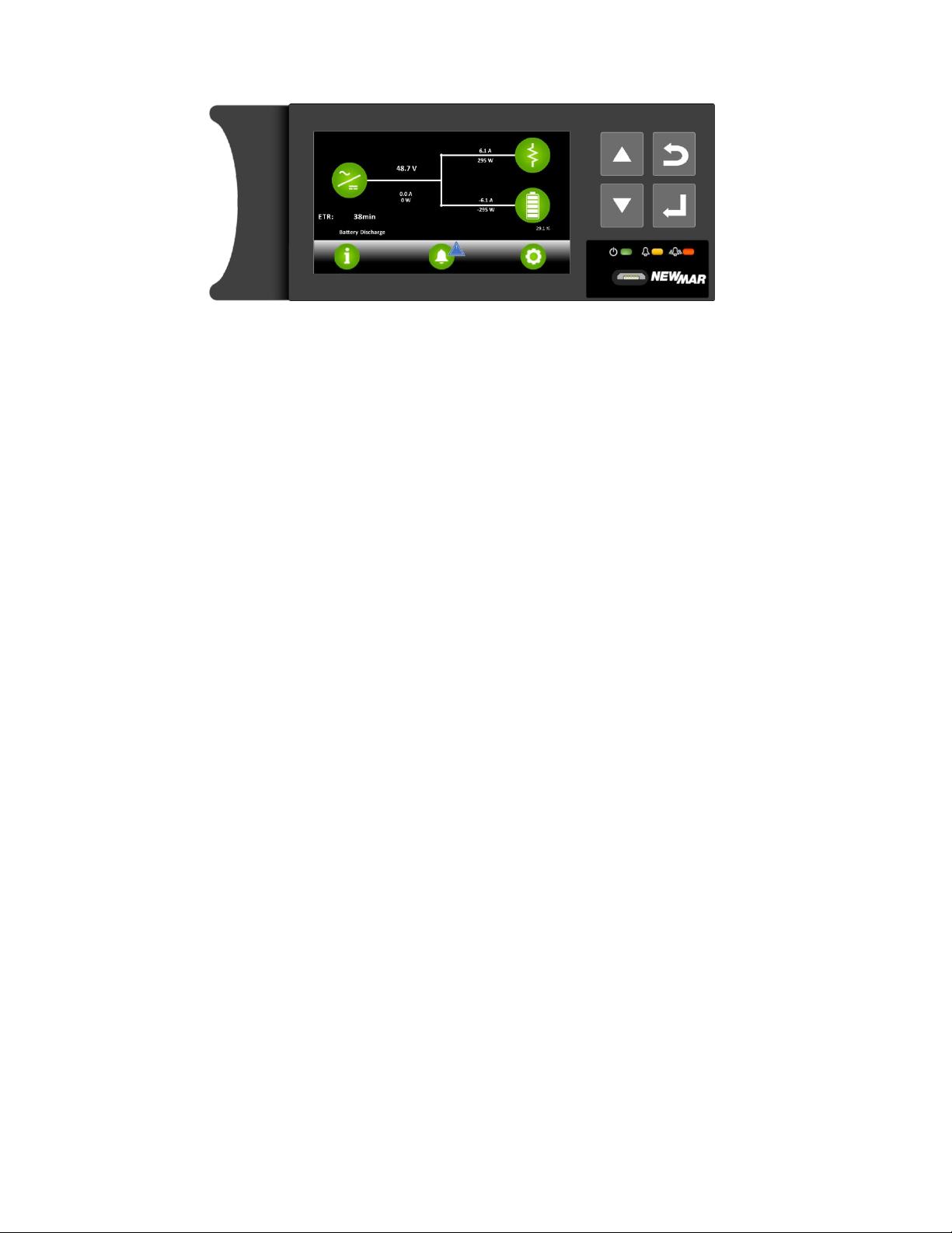
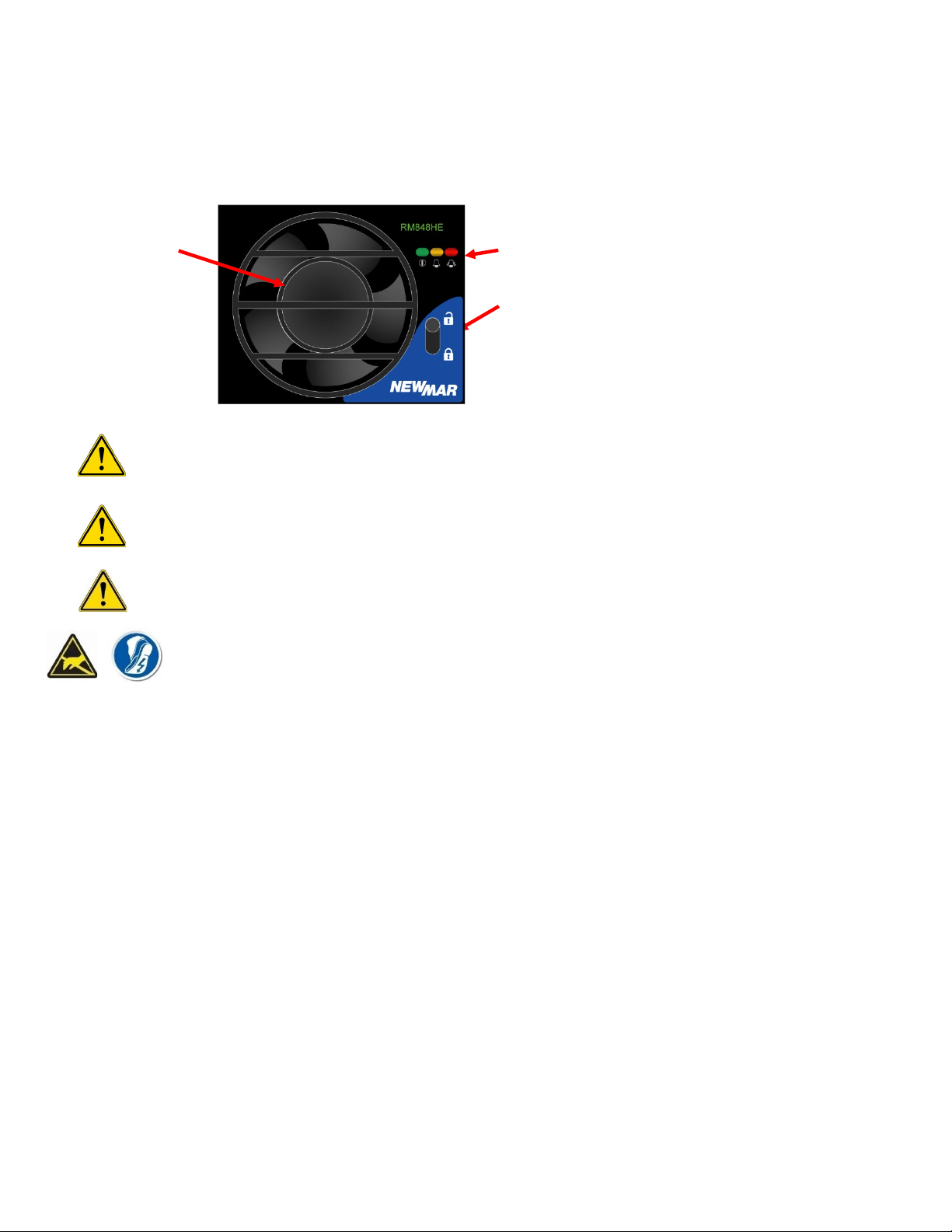
5.3. Alarms and Status Indicators
•Status LEDs:
◦Red LED Urgent alarm state.
◦Orange LED Non-Urgent alarm
◦Green LED DC power is connected to the unit; Energy Manager is functioning
NOTE:The LED mapping can be user modified.
•The energy manager is fitted with an audible buzzer which can be configured to alert to any alarm depending on the alarm
mapping.
NOTE:To disable the buzzer when active, tap any button.
•Micro-USB Connector: can independently power the EM4x and provides access to the Web UI
Note: when there are multiple alarms raised the Active Alarm display cycles through the list. The complete list can be
viewed by tapping Alarms.
•Tap the buttons to navigate through the menus.
Note: the EM4x-01 has the option to PIN lock function change through the front screen interface. See the EM4x manual
for details.
5.4. EM4x Features
The EM4x microcontroller-based DC system energy manager provides the control and monitoring functions for all Newmar
Energy’s power systems. With an appropriate communications connection third party lithium battery can also be managed.
The EM4x monitors all power system conditions including DC voltage, rectifier current, battery current, battery temperature,
distribution failure and battery pack status. It has an in-built web-based configurator allowing setup of system parameters,
monitoring, updating and download of logs using a web browser as well as a front panel interface through which key
parameters are also configurable. Visual notification of alarm conditions is given by LEDs and a display mounted on the front
of the EM4x, with remote notification being enabled by relay contacts, RS232, or TCP/IP (using SNMP).
The EM4x utilizes a USB communications port which allows for local monitoring of system operations as well as pre-
commission and power down configuration of the Web UI.
The EM4x also incorporates the following features:
• Support for third-party external batteries, both lead-acid and lithium based
• Support for AC-DC rectifiers (24V and 48V Outputs)
• Network connectivity (web access)
• System voltage metering for primary system DC supply. (e.g., 48V primary DC output)
• Load, battery and rectifier current metering and alarms
• Active rectifier current share
• Automatic system voltage control
• Effectively unlimited alarm thresholds as standard, for use with multiple DC outputs
• Advanced monitoring, display and logging of battery packs, and system performance data
• Advanced hybrid site control and monitoring with patented anti-stall feature for generators.
• Phase balance controls for multi-phase and single-phase AC input management
• Sophisticated programmable logic control
• For lead-acid external batteries -
◦Battery and room temperature metering and alarms (when fitted with optional temperature sensors)
◦Temperature compensation of float voltage (when fitted with optional temperature sensors)
◦Manual equalize charging to prolong the life of the batteries
◦Periodic equalize charging to prolong the life of the batteries
◦Fast charging after battery discharge
◦Battery capacity remaining indication
◦Battery testing facility