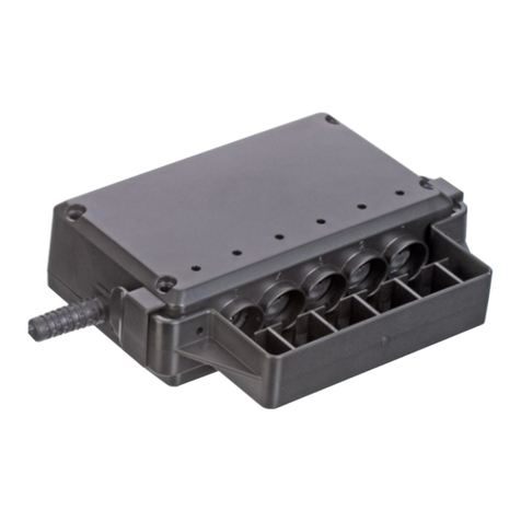
Intelligent Energy Power Path Module User manual

Power Path Module
User Manual
Users must read all instructions provided and retain the manual for future reference
Document No: 10010369

3
2
· Power Path Module (PPM) should only be used for UAV applications.
· All UAV pilots must be trained in the safe operation of the target UAV
and accredited by a regulatory body such as the FAA (US) or CAA (UK) or
another National Agency.
· The customer is responsible for ensuring all technicians and pilots are
suitably trained, accredited and in compliance with local laws and health
and safety regulations.
· The customer is responsible for ensuring the safe operation of the PPM
and UAV at all times.
· PPM should not be used in dusty, smoky or corrosive gas environments.
· Do not use PPM in rain or snow.
· Do not open or dismantle the PPM.
· Do not remove any external covers.
· Not to be used in residential areas (EMC).
1 Safety warnings 3
2 Power Path Module key components 4
3 The Power Path Module specification 5
4 Fuel Cell Power Module and
Power Path Module architecture 5
5 Assembly and connection 6
5.1 Mechanical mounting of the Power Path Module 6
5.2 Electrical interfaces 6
5.3 Output UART (Port 3) 7
6 Power Path Module Data 8
6.1 Output UART data format 8
6.2 SD card data 8
6.2.1 SD card data designation 8
6.2.2 Power Path Module fault codes 9
7 Connection of the Power Path Module 10
7.1 Single cylinder configuration 10
7.1.1 Power Path Module connections in a
single cylinder configuration 11
7.2 Connection procedure 11
8 Operation of the Power Path Module 12
8.1 Start-up 12
8.2 Shut down 12
8.3 Fault conditions 12
8.4 Troubleshooting 13
8.4.1 Amber LED fault 13
8.4.2 Red LED fault 13
9 Contact Intelligent Energy Product Support 13
10 End of Life treatment and disposal 13
11 EU Declaration of Conformity 14
Safety warnings1
This User Manual is intended as a general guidance only and does not purport to address the specific
situations that could potentially arise from the use of fuel cell systems and the Power Path Module
and their usage in connection with all stationary and UAV applications. The recipient is responsible
for ensuring that all personnel have read and understood this User Manual before being allowed to
handle, operate, install and store any equipment supplied by Intelligent Energy.
The recipient must ensure that any personnel responsible for operating fuel cell and the Power Path
Module are suitably trained and certified in compliance with any applicable local, state and federal
laws and regulations and good industry practice. The recipient is responsible for complying with any
relevant health and safety policies and procedures that may apply to the operation of stationary and
portable power applications, and use and storage of hydrogen on any sites.
Intelligent Energy warrants to the recipient and it will repair and replace any defective equipment
resulting from the authorised use of the equipment provided. Notwithstanding the above, Intelligent
Energy, to the fullest extent permitted by law, accepts no liability (including liability in respect of any
error or defects in the fuel cell system) for any damage caused as a result of recipient’s unauthorised
use of the equipment provided. The recipient acknowledges that the manner in which the equipment
is stored, used or operated is not under the control of Intelligent Energy Limited.
Intelligent Energy has made every effort to ensure that this User Manual is accurate and disclaims
liability for any inaccuracies or omissions that may have occurred.
Contents
Federal Communications Commission (FCC) Statement
This equipment has been tested and found to comply
with the limits for a Class B digital device, pursuant to part
15 of the FCC rules. These limits are designed to provide
reasonable protection against harmful interference in a
residential installation. This equipment generates, uses
and can radiate radio frequency energy and, if not installed
and used in accordance with the instructions, may cause
harmful interference to radio communications. However,
there is no guarantee that interference will not occur in
a particular installation. If this equipment does cause
harmful interference to radio or television reception,
which can be determined by turning the equipment
off and on, the user is encouraged to try to correct the
interference by one or more of the following measures:
· Reorient or relocate the receiving antenna.
· Increase the separation between the
equipment and receiver.
· Connect the equipment into an outlet on a circuit
different from that to which the receiver is connected.
· Consult the dealer or an experienced
radio/TV technician for help.
This device complies with Part 15 of the FCC Rules.
Operation is subject to the following two conditions:
(1) this device may not cause harmful interference and
(2) this device must accept any interference received,
including interference that may cause undesired operation.
You are cautioned that changes or modifications not
expressly approved by the party responsible for compliance
could void the user’s authority to operate the equipment.
The CE label shows that the product complies with the
basic requirements of the applicable directives. For the
declaration of conformity contact the manufacturer at
product.support@intelligent-energy.com

5
4Power Path Module key components The Power Path Module specification2 3
4
5 Input Power Connection FCPM 1
8 Input Power
Connection
FCPM 2
6 FCPM 1 UART
11 FCPM 2 Pressure
7 FCPM 1 Pressure
10 FCPM 2 UART 9 Service Port
1Output Power Connection
3Output UART
2Output Pressure
4PPM SD card
The major components of the PPM are as follows: Power Path Module Dimensions 110 × 95 × 25 mm
Weight 150g
Weight of PPM cables 75g
Max power output (continuous) 1600W
Max power output (peak) 2800W
32A@50V
Output voltage range 38.4 to 50V
FCPM 1 input voltage range 19.6 to 25V
FCPM 2 input voltage range 19.6 to 25V
Environmental
operating conditions
Operating temperature range +5° to +35°C
Storage temperature – 40° to +70°C
Fuel Cell Power Module and Power Path Module
architecture
The PPM allows you to connect two Intelligent Energy UAV Fuel Cell Power Modules
(FCPM) in series to provide a rated continuous power output of up to 1600W.
The PPM accepts inputs from 650W and 800W FCPMs. It is possible to use the PPM
with 2 × 800W FCPMs or 2 × 650W FCPMs.
Note: The FCPMs must be of the same rating.
The PPM can be operated in a single or dual hydrogen cylinder configuration,
see Section 7 for information.

7
6Assembly and connection Assembly and connection5 5
5.1 5.3
5.2
Mechanical mounting of the Power Path Module
Ensure that the PPM is well secured to the UAV. It is recommended that the PPM is
mounted using adhesive backed Velcro.
Electrical interfaces
The PPM has 11 electrical connections. These are summarised in the table below.
The PPM is supplied with cables to connect onto the UAV. The FCPMs should be
connected using their supplied cables.
For more detail on Port 7 and 11 see Section 7.2.
Output UART (Port 3)
The communication port is in UART format. This should be fitted in flight to allow
the fuel status and fault statuses to be viewed.
Socket: Manufacturer: JST; Part Number: S8B-ZR-SM4A-TF(LF)(SN)
Plug: Manufacturer: JST; Part Number: ZHR-8
Crimps: Manufacturer: JST; Part Number: SZH-002T-P0.5
Port number Description Connect to When required
1Output power connection UAV power input All cases
2Output pressure Regulator control All cases
3Output UART To UAV controller All cases
4PPM SD card NA All cases
5Input power
connection FCPM 1
FCPM 1 output All cases
6FCPM 1 UART FCPM 1 UART All cases
7FCPM 1 pressure FCPM 1 regulator interface If this port is left empty
for dual operation port 11
must be used
8Input power
connection FCPM 2
FCPM 2 output All cases
9Intelligent Energy use only NA NA
10 FCPM 2 UART FCPM 2 UART All cases
11 FCPM 2 pressure FCPM 2 regulator interface If this port is left empty
for dual operation port 7
must be used
Pin number Description Comment
1+3V3 Output Power Rail – not for use
to power external circuits
+3V3
2UART TX FCPM UART transmit line (TX) to
connect to external receive (RX) line
UART TX
3UART RX FCPM UART receive line (RX) to connect
to external transmit (TX) line
UART RX
4Not used Not currently used N/A
5Not used Not currently used N/A
6Not used Not currently used N/A
7Not used Not currently used N/A
8GND GND reference – GND
Warning Ensure the correct polarity of the two FCPMs.
Do not connect more than one FCPM debug cable to a computer.
The signals are not isolated. When the FCPMs are connected in series
the ground levels will be different.
Warning Protect the PPM from direct water spray or water drips.

9
8Power Path Module Data PPM Data6 6
6.1
6.2
6.2.1
6.2.2
Output UART data format
The communication port has a serial format. The parameters are as follows:
UART: 9600 baud, 8 data bits, 1 stop bit, and no parity
Format: There are 14 messages in the data stream
A typical message from the UART will be formatted as follows:
<6708,85.0,75.0,2,00000000,85.0,78.0,2,00000000,85.0,1800.0,45.00,40.00,249>
SD card data
The SD card contains data from the operation of the fuel cells.
SD card data designation
On the SD card there will be a folder called Data containing .csv files with the
columns having the following headings:
Power Path Module fault codes
The fault codes for the PPM as stored in the PPM SD card are shown below.
For fault codes from the FCPM SD card refer to the FCPM User Manual.
The naming of the unit is covered in N type rows. Serial number will be displayed as
a 15 digit alpha numeric. The software version will be displayed in the format X.XX.
Data title Units Description
Time Secs Time from when PPM
powered on
FCPM #1 Tank Pressure % 0 to 100 (5Bar to 300Bar)
FCPM #1 Battery Level % 0 to 100 (19.6V to 24V)
FCPM #1 State N/A 0 to 8
FCPM #1 Fault Codes N/A 00000000 to 80000000
FCPM #2 Tank Pressure % 0 to 100 (5Bar to 300Bar)
FCPM #2 Battery Level % 0 to 100 (19.6V to 24V)
FCPU #2 State N/A 0 to 8
FCPU #2 Fault Codes N/A 00000000 to 80000000
Tank Pressure Bar 0 to 300
Output Power Watt 0 to 2800
Output Voltage Volt 0 to 50
Output Current Amp 0 to 50
Bit Statuses (5×DI, 1×DO) N/A 000000 to 11111
Data title Units Description
FCPM #1 Tank Pressure % 0 to 100 (5Bar to 300Bar)
FCPM #1 Battery Level % 0 to 100 (19.6V to 24V)
FCPM #1 State N/A 0 to 8
FCPM #1 Fault Codes N/A 00000000 to 80000000
FCPM #2 Tank Pressure % 0 to 100 (5Bar to 300Bar)
FCPM #2 Battery Level % 0 to 100 (19.6V to 24V)
FCPU #2 State N/A 0 to 8
FCPU #2 Fault Codes N/A 00000000 to 80000000
Tank Pressure Bar 0 to 300
Output Power Watt 0 to 2800
Input Voltage Volt 0 to 50.
The sum of the output
voltages for the two FCPMs
Output Current Amp 0 to 50
Output Voltage 0 to 50 Volt Output voltage from the
PPM
5xDI, 1xDO bit statuses N/A 000000 to 11111
Software Version N/A 1.00 to 9.99
PPM Serial Number N/A 15 characters (alphanumeric)
SPPM Fault Code N/A 00000000 to 80000000
Fault code Description Condition Sustained delay (s)
80000000 The Master Output FET has
failed short
Master Output not enabled
and voltage difference across
the Ideal Diode less than 3V
0.50
40000000 The Master Output FET has
failed to switch on (allow
current)
Master Output enabled and
voltage difference across the
Ideal Diode greater than 3V
0.50

11
10 Connection of the Power Path Module Connection of the Power Path Module7 7
7.1
7.2
7.3 Connection procedure
1 Check that both FCPMs are in the Off state (No LED present)
2 Connect the Communication cables for FCPM1
3 Connect the Power cable for FCPM1
4 Connect the Communication cables for FCPM2
5 Connect the Power cable for FCPM2
6 Connect the Output Communication cables
7 Connect the Output Power cable
For the various connections to the PPM the following diagrams use the
following key:
Dual cylinder configuration
In this configuration each FCPM is supplied with fuel from a separate cylinder.
The PPM manages the signals from each and creates one data stream to the UAV.
Single cylinder configuration
In this configuration each FCPM is connected to the same cylinder.
The PPM manages the signals from each and creates one data stream to the UAV.
Additionally, each diagram has the port for the connection to the PPM labelled.
Power Cable
Hydrogen Feed
Regulator Connection
UART Connection
PPM
FCPM 1 FCPM 2
5
8
6
10
7
11
1 2 3
Connection to UAV
PPM
Connection to UAV
FCPM 1 FCPM 2
5
8
6
10
7
1 2 3
Note: Diagram is for the FCPM 1 cylinder to be connected to the PPM. But the PPM
can operate with the Regulator connection from either unit FCPM. The signal from
the other regulator must be connected to the respective side of the PPM on either
Port 11 or 7.

13
12 Operation of the Power Path Module Operation of the Power Path Module
Contact Intelligent Energy Product Support
8 8
9
8.1 8.4
8.4.1
8.4.2
Note:
8.2
8.3
Start-up
The start-up procedure for the Fuel Cell including a PPM, is the same as it would
be to operate the FCPMs separately. It is recommended that each FCPM is
allowed to complete the full start-up process. The procedure to start-up is as
follows:
1 Long Press the start button on FCPM 2 (Button press = 3sec)
2 Press the start button on FCPM 2 for 3sec
3 Wait 90 seconds
4 Blip the start button on FCPM 1 (Button press = 0.5sec)
5 Blip the start button on FCPM 2 (Button press = 0.5sec)
6 Check that both FCPMs are operating (flashing green LED on the FCPM)
For there to be voltage at the output of the PPM, both FCPMs need to be operational
Shutdown
The Shutdown procedure when operating with a PPM is as follows:
1 Long Press the start button on FCPM 1 (Button press = 3sec)
2 Long Press the start button on FCPM 1 (Button press = 3sec)
3 Disconnect the Hybrid Battery from FCPM 1
4 Disconnect the Hybrid Battery from FCPM 2
Fault conditions
If the PPM detects a problem, it will indicate it via the LED.
Troubleshooting
Amber LED fault
If the Amber LED light is shown: check that both FCPMs are operating
and the cables are correctly connected.
Red LED fault
If the Red LED light is shown: check both FCPMs for a red LED, on the FCPM with the
fault light check the fault code it is giving, via the UART port or from the data on the
FCPM SD card
LED Colour LED Mode Status
Green Flash Two FCPMs connected
Amber Flash Waiting for second FCPM to connect
Data missing from an FCPM
Output below 35V
Red Flash FCPM in fault mode
End of Life treatment and disposal10
For all other issues and questions please contact your local
Intelligent Energy representative or the Product Support team by email
When the PPM reaches end of life please contact Intelligent Energy for support with
reconditioning or disposal at product.support@intelligent-energy.com

15
14 EU Declaration of Conformity11
Intelligent Energy Limited
of
Charnwood Building, Holywell Park, Ashby Road, Loughborough, Leicestershire,
United Kingdom, LE11 3GB
In accordance with the following Directive(s):
· 2014/30/EC The Electromagnetic Compatibility Directive
· 2014/95/EU General Product Safety Directive
Hereby declares that:
· Power Path Module (PPM)
Is in conformity with the applicable requirements of the Directives set out above and the
following standards documents:
· EN 61000-6-2:2005 Electromagnetic compatibility (EMC) –
Generic standards – Immunity for
industrial environments
· EN 61000-6-4:2007+A1:2011 Electromagnetic compatibility (EMC) –
Generic standards – Emission standard
for industrial environments
A copy of the official version of this certificate duly signed by an authorised
signatory of the manufacturer is available upon request by emailing
sales@intelligent-energy.com
Intelligent Energy Limited, Charnwood Building, Holywell Park, Ashby Road,
Loughborough, Leicestershire, United Kingdom, LE11 3GB

© Intelligent Energy Limited 2020. All Rights Reserved.
The information contained herein is the intellectual property of Intelligent Energy Ltd and it may not be copied or reproduced in any format.
The information contained in this publication is intended only as a guide and is subject to change as a result of the constant evolution of Intelligent
Energy’s business and its technology. This publication and its contents do not include all details which may be relevant to particular circumstances and
should not be regarded as being a complete source of Information. To the fullest extent permitted by law, Intelligent Energy offers no warranty as to
the accuracy of the content of this publication, shall not be liable for the content of this publication and no element of this publication shall form the
basis of any contractual relationship with a third party. Printed January 2020. 56708-IE-UM-202001
Published by: Intelligent Energy Ltd, Charnwood Building, Holywell Park, Ashby Road, Loughborough LE11 3GB. Tel: +44 (0) 1509 271 271
Document No: 1038842
(Registered in England with company number: 03958217).
T+441509 271 271 Eproduct.support@intelligent-energy.com
Intelligent Energy Charnwood Building, Ashby Road, Loughborough, LE11 3GB, UK
www.intelligent-energy.com
Table of contents
Other Intelligent Energy Control Unit manuals
Popular Control Unit manuals by other brands
Honeywell
Honeywell SILEN KNIGHT IDP-Zone-6 Installation and maintenance instructions
Digilent
Digilent PmodGPS Reference manual
Stanley
Stanley BTM-51190 manual
GF
GF MSA 2.0 instruction manual
LIFE home integration
LIFE home integration RG1RE Instructions and warnings for installation, use and maintenance

Zurn Wilkins
Zurn Wilkins P4000A Installation, Start-up, Maintenance Instructions
