MIQ/24V Installation
3 - 1
ba64114e02 08/2006
3 Installation
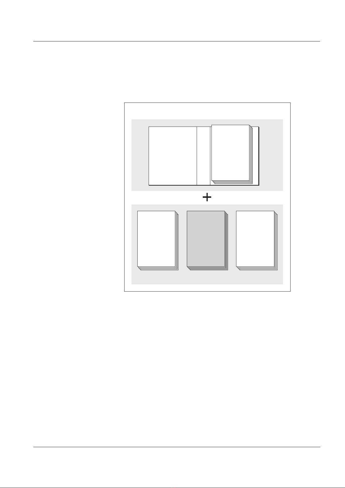
3.1 Scope of delivery
The scope of delivery of the MIQ/24V is listed in the INSTALLATION
chapter of the system operating manual.
3.2 Installation in the IQ SENSOR NET
The IQ SENSOR NET provides a number of options for integrating the
MIQ/24V mechanically and electrically in the system (stacked
mounting, distributed mounting, etc.). The individual types of instal-
lation are described in detail in the INSTALLATION chapter of the system
operating manual.
Note
To achieve optimum heat transfer, it is recommended to always place
the power supply module at the back of a module stack.
Note
If there are several power supply modules in the IQ SENSOR NET, it is
helpful if all the power supply modules are connected to a single power
supply. As a result, the system can be easily switched on and off from
a single location.
3.3 Connecting the 24 V AC/DC supply
Warning
If the power supply is connected incorrectly, it may represent a
danger to life from electric shock. Pay attention to the following
points during installation:
!
!!
!The power supply must fulfill the specifications given on the
nameplate and in chapter 5 TECHNICAL DATA (Safety Extra Low
Voltage SELV).
!
!!
!The MIQ/24V may only be connected to the 24 V AC/DC supply
by a trained electrician.
!
!!
!The connection of the MIQ/24V may only be carried out when
the supply is not carrying any voltage.
!
!!
!When installed in a building, a switch or power switch must be
provided as a disconnecting device for the MIQ/24V.
The interrupt facility must:
– be installed in the vicinity of the MIQ/24V, easily accessible
by the user, and
– identified as a disconnecting device for the MIQ/24V.