Intelligent Energy FCPM User manual
2.4kW UAV Fuel Cell
Power Module
User Manual
Users must read all instructions provided and retain the manual for future reference
Document No. 10010371

2Glossary
This is the user manual for the 2.4kW Fuel Cell Power Module (FCPM)
designed and manufactured by Intelligent Energy.
Users of this product must follow the instructions and warnings laid out in
this user manual at all times and must be aware of the hazards present when
using high pressure ammable gas products and high voltage electronics.
This User Manual is intended as a general guidance only and does not purport
to address the specic situations that could potentially arise from the use of
fuel cell systems and their usage in connection with UAVs. The recipient is
responsible for ensuring that all personnel have read and understood this
User Manual before being allowed to handle, operate, install and store any
equipment supplied by Intelligent Energy.
The recipient must ensure that any personnel responsible for handling
hydrogen cylinders and operating UAVs are suitably trained and certied in
compliance with any applicable local, state and federal laws and regulations
and good industry practice. The recipient is responsible for complying with
any relevant health and safety policies and procedures that may apply to
the operation of UAVs and use and storage of hydrogen on any sites.
Intelligent Energy warrants to the recipient and it will repair and replace any
defective equipment resulting from the authorised use of the equipment
provided. Notwithstanding the above, Intelligent Energy, to the fullest extent
permitted by law, accepts no liability (including liability in respect of any error
or defects in the fuel cell system and UAVs) for any damage caused as a result
of recipient’s unauthorised use of the equipment provided. The recipient
acknowledges that the manner in which the equipment is stored, used or
operated is not under the control of Intelligent Energy Limited. Intelligent
Energy has made every eort to ensure that this User Manual is accurate and
disclaims liability for any inaccuracies or omissions that may have occurred.
Federal Communications Commission (FCC) Statement
This equipment has been tested and found to comply with the limits for a Class A
digital device, pursuant to part 15 of the FCC rules. These limits are designed to
provide reasonable protection against harmful interference in a residential
installation. This equipment generates, uses and can radiate radio frequency
energy and, if not installed and used in accordance with the instructions, may cause
harmful interference to radio communications. However, there is no guarantee that
interference will not occur in a particular installation. If this equipment does cause
harmful interference to radio or television reception, which can be determined by
turning the equipment o and on, the user is encouraged to try to correct the
interference by one or more of the following measures:
• Reorient or relocate the receiving antenna.
• Increase the separation between the equipment and receiver.
• Connect the equipment into an outlet on a circuit dierent from that to
which the receiver is connected.
• Consult the dealer or an experienced radio/TV technician for help.
This device complies with Part 15 of the FCC Rules. Operation is subject to
the following two conditions:
(1) this device may not cause harmful interference and
(2) this device must accept any interference received, including interference
that may cause undesired operation. You are cautioned that changes or
modications not expressly approved by the party responsible for
compliance could void the user’s authority to operate the equipment.
CE Marking Statement
The CE label shows that the product complies with the basic requirements of
the applicable directives. For the declaration of conformity contact the
Glossary of terms
Term Denition
Function or
Description
FCPM Fuel Cell Power
Module
The entire fuel
cell system
SPM (1&2) Stack Power Module There are two SPMs
housing the two fuel
cell stacks and
associated power
electronics
PCM Power Control
Module
Digital and analogue
HMI ports, micro SD
card and regulator
interface, part of
centre module
BDM Battery Diagnostic
Module
Not currently used
POM Power Output
Module
Centrally located
board where battery
connections and
output power
connections are
made. Part of centre
module
UART Universal
Asynchronous
Receiver/Transmitter
UART’s main purpose
is to transmit and
receive serial data
CAN Controller Area
Network A & B
Communication
protocol
LW Light Weight Light Weight
Regulator
HFLW High Flow Light
Weight
High Flow Light
Weight Regulator

3Contents
1 Safety warnings 4
2 Key components 5
2.1 Product specication 5
2.2 System diagram 6
3 Assembly 9
3.1 Connecting output power cables 9
3.1.1 Disconnecting SPMs from central module 10
3.1.2 Connecting SPM to central module 11
3.2 Mounting 12
3.2.1 Mounting point information 12
3.2.2 Mounting dimensions 13
3.3 Air ow restrictions 13
3.3.1 Electronics air ow 13
3.3.2 SPM cooling fans 14
4 Hydrogen connection 14
4.1 Connector specication 14
4.2 Hydrogen specication 14
4.3 Hydrogen High Flow Light Weight (HFLW) Regulator 15
4.4 Connecting the FCPM and HFLW Regulator 15
5 Electrical connections 16
6 Operating the FCPM 17
6.1 Startup using the Start button 17
6.2 Startup using digital signal 17
6.3 Shutdown using the Start button 17
6.4 Shutdown using digital signal 17
6.5 Monitoring of data output 17
6.6 Software update procedure 18
6.7 Conguration update procedure 18
6.8 LED states 18
7 Logging and data connections 19
7.1 SD card formatting 19
7.2 SD card data format 19
7.3 Conguration format 19
7.3.1 Conguration parameter denitions 19
7.4 UART format 20
7.5 CAN format 21
7.5.1 CAN data to FCPM 21
7.5.1 CAN Data sent by FCPM 22
8 Electrical considerations 24
8.1 Battery charge limits 24
8.2 Emergency battery usage 24
8.3 Specifying a battery 24
8.4 Specifying a hybrid battery cable 24
9 Storage and maintenance 25
9.1 User maintenance 25
9.2 Recommended storage 25
10 Troubleshooting 26
10.1 Fault codes 26
10.2 Contact Product Support 26
11 End of life treatment and disposal 26
12 Appendix 27
12.1 Connector specications 27
12.1.1 Regulator Interface [Port No 10] 27
12.1.2 HMI Analogue/Digital [Port No 9] 27
12.1.3 UART and CAN [Port No 8] 28
12.1.4 Battery diagnostics module
(Battery Volts or CVM) [Port No 6&7] 28
12.1.5 FCPM In [Port No 4] 28
12.1.6 FCPM Out [Port No 5] 28
12.2 Fault codes 29
12.2.1 PCM fault codes 29
12.2.1 SPM1 & 2 fault codes 32

41 Safety warnings
• Only qualied technicians trained in high pressure ammable gases must carry out
tting of regulators and lling of cylinders and do so in accordance with local laws
and Health and Safety (H&S) regulations.
• The customer is responsible for ensuring all technicians and pilots are suitably
trained, accredited and operate in compliance with local laws and H&S regulations.
• The customer is responsible for ensuring the safe operation of the FCPM in line with
the User Manual at all times.
• This device requires oxygen to operate.
• A minimum of 1m3/min of oxygen is required for operation.
• Up to of 20m3/min air is required for cooling.
• FCPM not to be used in dusty, smoky or corrosive gas environments.
• Do not use FCPM in rain or snow.
• During integration there is a risk of exposed electrical conductors.
• Pressurised hydrogen present. Highly ammable!
• Do not operate the FCPM if the casing is damaged or missing.
• FCPM should be inspected for damage and checked for leaks prior to use.
• Do not transport the FCPM with the hydrogen supply connected.
• Do not remove casing from Module
• Do not use this FCPM if any part has been immersed or ooded with water.
Immediately call the manufacturer or manufacturer’s representative to inspect
the FCPM and to replace any functional part that has been aected.

52 Key components
2.1 Product specication
Power characteristics Maximum continuous fuel cell power 2400W
Peak power with default battery
Maximum power with suitable battery (not to be exceeded)
4800W
8000W
Output voltage (congurable, regulated and steady output) 40 – 70V
Fuel Cell Power Module (FCPM) dimensions 130 × 430 × 230mm
Other characteristics Mass 4400g
Light weight hydrogen regulator mass 250g
Maximum regulator (cylinder) pressure 300Bar
(4350PSI)
Output pressure 0.7Bar ± 0.25Bar
(10PSI ± 3PSI)
Hydrogen consumption rate g/hr @ 2.4kW 160-190g/hr
Hybrid batteries Two default hybrid batteries (congurable) 2 × 6S in series
Dimensions (per battery) 130 × 40 × 40mm
Mass (per battery) 535g
Capacity (per battery) 3300mAh
Environmental
operating conditions
Startup temperature +5°C to 40°C
Operating temperature -5°C to 40°C
Storage temperature -10°C to 70°C
System warranty 1000hrs
Safety features Dual redundant power system and backup battery
Other features Internal data storage for rmware update, performance and
diagnostics SD card communication port; to UAV FCPM or
accessories UART/CAN
FCPM is not IP rated
Output electrical connector M8 ring terminal/AS150
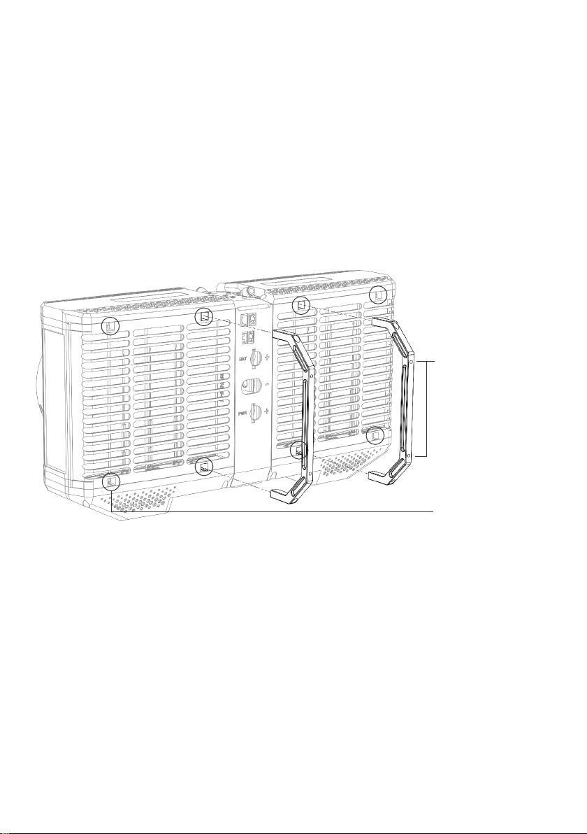
62 Key components
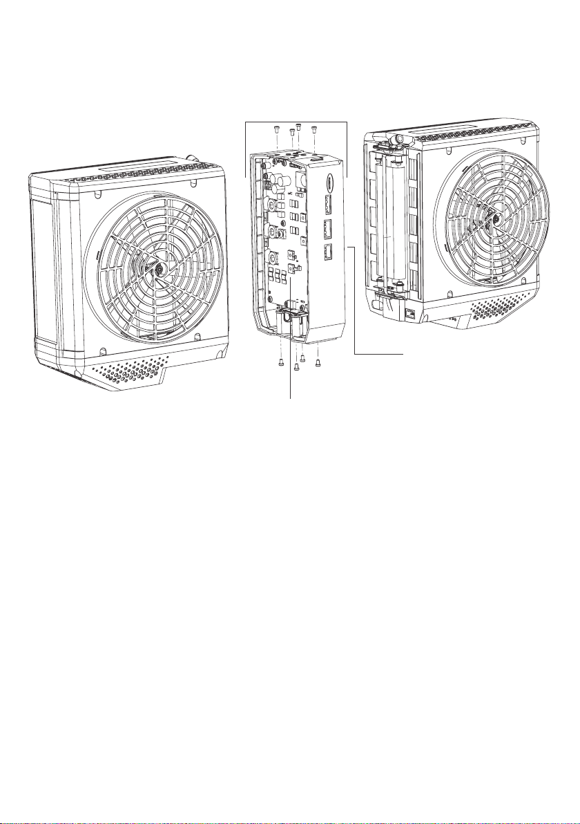
2.2 System diagram
Stack Power Module 1 (SPM 1) Power Output Module
(POM)
FCPM exploded rear view
Central Module
Power Control Module (PCM)
Stack Power Module 2 (SPM 2)
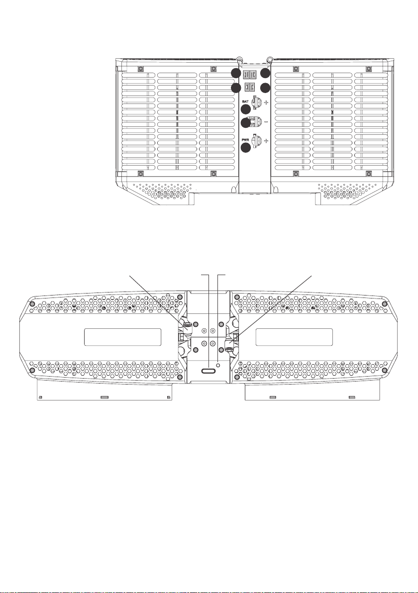
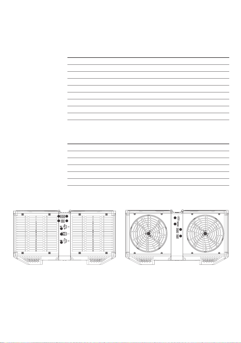
72 Key components
SPM 1 Hydrogen Inlet SPM 2 Hydrogen Inlet
1. Ground
2. Positive Output
3. Battery Positive
4. FCPM In
5. FCPM Out
6. Battery Diagnostic
Module (BDM) 2
7. Battery Diagnostic
Module (BDM) 1
Start Button Status LED
Fuel Cell Power Module (FCPM) Front view
FCPM Top View
SPM 2
SPM 1 Central Module
Central Module SPM 1
SPM 2
6
3
1
2
7
4 5

82 Key components
8. HMI (UART/CAN)
9. HMI (Digital/Analogue)
10. Regulator Interface
11. SD Card
SPM 1 Electronics Cooling Fan SPM 2 Electronics Cooling Fan
Power Control
Module (PCM)
FCPM Rear View
Bottom View
SPM 2 Central Module SPM 1
11
10
9
8

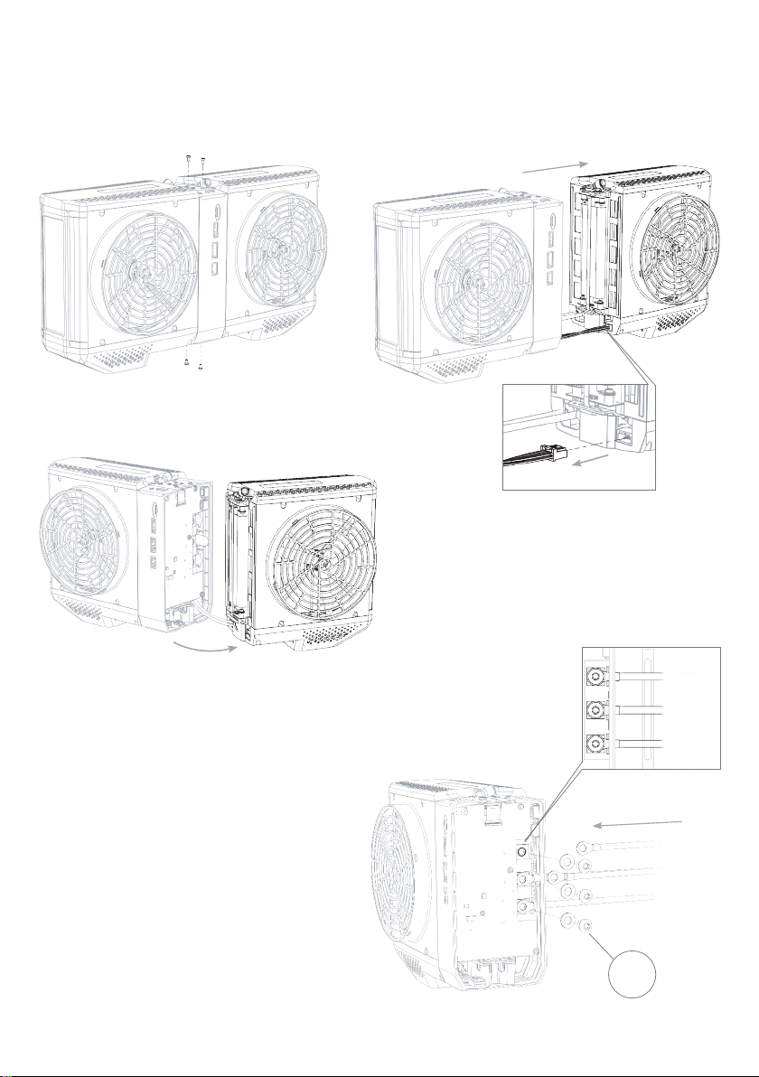
93 Assembly
3.1 Connecting output power cables
The output power leads can be connected to the FCPM once the PCM has
been disconnected.
Note All the power leads require an M8 ring terminal to attach to the POM.
1. Ensure battery is isolated from the cables before connecting to the POM,
use a suitable connector between battery and ring terminals for the power
rating of the application.
2. Complete the steps to open the FCPM section 3.1.1.
3. Feed the cable through the housing, connect battery positive M8 Ring
to ‘Batt +’ and battery negative to common ground ‘GND’.
4. Connect load positive to ‘PWR +’ and load negative to common ground ‘GND’.
5. Use the bottom terminal with an M8 button head screw to attach the cable
(max. torque 1.5Nm).
6. Feed the cable through the housing, battery positive (connector 3).
7. Use the top terminal with an M8 button head screw to attach the cable
(max. torque 1.5Nm).
8. Feed both the battery negative cable and the output negative cable through
the housing, ground (connector 1).
9. Use the middle terminal with an M8 button head screw to attach the cable
(max. torque 1.5Nm).
10. Once the cables are in place reconnect the SPM as in section 3.1.2.
Note The negative stud is common to the battery and output
STEP 1 STEP 2
STEP 4 STEP 5
STEP 3
BAT +
GND x2
PWR +
1.5 N/m
* SPM 2 removed for clarity * Steps 1-3 in reverse
STEP 1 STEP 2
STEP 4 STEP 5
STEP 3
BAT +
GND x2
PWR +
1.5 N/m
* SPM 2 removed for clarity * Steps 1-3 in reverse
STEP 1 STEP 2
STEP 4
STEP 5
STEP 3
BAT +
GND x2
PWR +
1.5 N/m
* SPM 2 removed for clarity
* Steps 1-3 in reverse
10 3 Assembly
3.1.1 Disconnecting SPMs from central module to allow power connection

STEP 1 STEP 2
STEP 4 STEP 5
STEP 3
BAT +
GND x2
PWR +
1.5 N/m
* SPM 2 removed for clarity * S
teps 1-3 in reverse
STEP 1 STEP 2
STEP 4 STEP 5
STEP 3
BAT +
GND x2
PWR +
1.5 N/m
* SPM 2 removed for clarity * Steps 1-3 in reverse
STEP 1 STEP 2
STEP 4 STEP 5
STEP 3
BAT +
GND x2
PWR +
1.5 N/m
* SPM 2 removed for clarity * Steps 1-3 in reverse
STEP 1 STEP 2
STEP 4 STEP 5
STEP 3
BAT +
GND x2
PWR +
1.5 N/m
* SPM 2 removed for clarity * Steps 1-3 in reverse
113 Assembly
3.1.2 Connecting SPM to central module
12 3 Assembly
3.2 Mounting
3.2.1 Mounting point information
Each SPM has four mounting points which accept an M3 thread. Mounting brackets
are provided which can be xed to the SPMs and have two M4 through holes for
customer use. The complete assembly must have a minimum of two mounting
brackets in total. Each SPM must have at least one support.
Recommended mounting points on the system are labelled in the gure below.
Two optional mounting brackets are included. These can be used to aid integration
and can be attached to any of the labelled mounting points.
The 2.4kW unit must be securely attached to the vehicle or test xture.
Mounting bracket: 2x M4
tapped threads per bracket
Mounting bracket: 8x M3 x 5mm
threaded holes per system

131,0
363,0
168,0
100,0
116,0
34,0
133 Assembly
3.2.2 Mounting dimensions
The locations of the mounting points are shown in the diagram below:
3.3 Air ow restrictions
3.3.1 Electronics air ow
Up to 1m3/min of airow is required to the power electronics located at the bottom of
each SPM. Do not cover the vents when mounting, airow must not be blocked when
operating the FCPM.
SPM 1 Power electronics fans
Do not cover
SPM 2

14 3 Assembly
4 Hydrogen connection
3.3.2 SPM cooling fans
The two mounting brackets are included to aid the creation of an air gap. This is
required to allow up to a 20m3/min of airow through the FCPM. It is important
to have an even airow distribution to both SPMs allowing the system to work
eciently, if the air is being recirculated a minimum of 1m3/min of supplemental
oxygen is required.
4.1 Connector specication
The hydrogen is supplied to each SPM via 6mm OD x 4mm ID push t tube.
A hydrogen compatible material with anti-static and low hydrogen permeability
is required.
Recommended tubing: 6mm OD x 4mm ID, anti-static, polyurethane
SMC TAU0604B-20
4.2 Hydrogen specication
When installing and operating hydrogen systems, hydrogen general safety guidance
should be considered:
ISO/TR 15916 – basic considerations for the safety of hydrogen systems for more
detailed information.
The hydrogen purity should comply with the specication in the table below:
Fuel Characteristics Fuel Requirements
Hydrogen concentration > 99.90%
Nitrogen, Helium, Argon < 0.10%
Oxygen < 50ppm
Carbon Dioxide < 2ppm
Carbon Monoxide < 0.2ppm
Ammonia < 0.1ppm
Sulphur containing compounds < 4ppb
Max particle concentration < 1mg/kg
Max particle diameter < 75µm

Refuelling Port
Hydrogen Output Port
Pressure Relief Valve
Pressure Transducer
Burst Disc
Cylinder Thread
154 Hydrogen connection
4.3 Hydrogen High Flow Light Weight (HFLW) Regulator
The 2.4kW FCPM is designed to be operated with an Intelligent Energy HFLW Regulator.
Note The FCPM could be permanently damaged if operated with incorrect hydrogen
inlet pressure or insucient hydrogen ow.
4.4 Connecting the FCPM and HFLW Regulator
The HFLW Regulator is designed to be connected to an Intelligent Energy FCPM.
Please refer to the Light Weight (LW) Regulator user manual for details of how to
mount the Regulator to the cylinder. The HFLW regulator gas connections are
identical to the LW Regulator so may be used for reference.
https://www.intelligent-energy.com/uploads/product_guides/53527_IE_-_
Lightweight_Hydrogen_Regulator_User_Manual_August_2019.pdf
Note Ensure the hydrogen cylinder and FCPM are securely mounted
before proceeding.
1. Verify the connector O-rings are in place
and free from damage or debris.
2. Align the hose connector path with
the regulator pins.
3. Push the hose connector and twist anti-clockwise.
It will click when located.
16 5 Electrical connections
In order to function, the FCPM must have the following attached to the unit.
See section 2.2 for reference to connection locations.
Connection No. Description Comments
1Output negative Common ground
1Battery negative Common ground
2Output positive Output is live once battery connected
3Battery positive Ensure battery has isolating connector
8HMI UART/CAN At least one HMI interface must be in place
9HMI Analogue/Digital At least one HMI interface must be in place
10 Regulator interface
H2 SPM1 Hydrogen in 1 Hydrogen connection SPM1
H2 SPM2 Hydrogen in 2 Hydrogen connection SPM2
Current ports that are not used or are optional for operation are:
Connection No. Description Comments
4FCPM Out Do not use – If connected unit is slave
5FCPM In Do not use – unit is master if not connected
6Battery diagnostics out Do not use
7Battery diagnostics in Do not use
8HMI UART/CAN At least one HMI interface must be in place
9HMI Analogue/Digital At least one HMI interface must be in place
For details of the pin outs for all connectors see appendix section 12.1
10. Regulator Interface 8. HMI (UART/CAN)11. SD Card 9. HMI (Digital/
Analogue)
FCPM Rear view
SPM 2 Central Module SPM 1
11
10
9
8
6. Battery Diagnostic
Module (BDM) 2
7. Battery Diagnostic
Module (BDM) 1
4. FCPM In
3. Battery
Positive
5. FCPM Out
2. Positive
Output
1. Ground
FCPM Front view
SPM 2 Central Module SPM 1
6
3
1
2
7
4 5

176 Operating the FCPM
6.1 Startup using the Start button
Note When the battery is connected, the output is live!
1. Check at least one HMI is connected.
2. Check regulator interface is connected.
3. Check fuel lines are connected to both SPMs.
4. Check that there is sucient fuel available.
5. Connect battery.
Note Output is now live
6. Press the start button until audible fan noise is heard (max 5 seconds).
7. Fuel cell startup process will begin.
8. Check error codes to ensure the system has started correctly.
9. When the LED is green fuel cell power is available (approx. 5 seconds after
starting system).
6.2 Startup using digital signal
For remote operation via a digital signal, use the process as outlined in section 6.1
Startup using the Start button. However, step 6 must be changed to:
1. Pull up (3.3V) start pins Start 1 and Start 2 on the HMI analogue/digital
connector for 4 seconds.
6.3 Shutdown using the Start button
The procedure to shut down the FCPM:
1. Press button for 4 seconds.
2. Wait until LED stops ashing orange before moving to next step
(removing battery early will corrupt the micro SD card).
3. Disconnect batteries.
4. Isolate hydrogen cylinder.
6.4 Shutdown using digital signal
For remote operation with a digital signal, use the process as outlined in section 6.3
Shutdown using the button. However, step 1 must be changed to:
1. Pull up (3.3V) start pins Start 1 and Start 2 on the HMI Analogue/Digital connector
for 4 seconds.
6.5 Monitoring of data output
See logging and data connections (section 7)
For operational safety during ight it is essential to monitor remaining
hydrogen fuel pressure, battery voltage, run state and error codes.
Not doing so could lead to unexpected loss of power.

18 6 Operating the FCPM
6.6 Software update procedure
To change the software on the SPM or PCM follow the steps below:
1. Power o FCPM.
2. Remove hybrid batteries.
3. Remove micro SD Card and open IntelligentEnergy folder on the micro SD card.
4. Copy the “Load SPM” or “Load PCM” le(s) and image folder into IntelligentEnergy
folder.
5. Re-insert micro SD card to the FCPM.
6. Reconnect batteries.
7. Wait for LED to change from rapid amber ashing to rapid green ashing.
8. Remove hybrid batteries.
9. Software update has been completed.
6.7 Conguration update procedure
To change the conguration of the SPM use the following procedure. The parameters
for the conguration can be found in section 7.3.
1. Power o FCPM.
2. Remove hybrid batteries.
3. Remove micro SD Card and open IntelligentEnergy folder on the micro SD card.
4. Copy the “Load Cong” le and image folder into IntelligentEnergy folder.
5. Re-insert micro SD card to the FCPM.
6. Reconnect batteries.
7. Wait for LED to change from rapid amber ashing to rapid green ashing.
8. Remove hybrid batteries.
9. Conguration update has been completed.
6.8 LED states
FCPM LED (located on top of central module next to start button) colour denotes
specic running states and errors, as follows:
Colour State Description
O Solid FCPM o
Green Flash Normal operation
Green Double Flash Output live fuel cell o
Green Rapid Flash Software update complete
Green Slow Flash Fuel cell starting
Amber Flash Low H2pressure
Amber Rapid Flash Software updating or entering sleep mode
Amber Double Flash Output live fuel cell o H2low pressure
Amber Slow Flash Fuel cell starting H2pressure low
Red Flash Fuel cell stopping
Red Rapid Flash Software update failed

197 Logging and data connections
7.1 SD card formatting
The FCPM takes a micro SD card. This logs health and performance data as well
as fault codes. The micro SD card format must be FAT32. No les are required for
initial operation, the FCPM will create the necessary les for operation.
7.2 SD card data format
The following folder structure must exist for the FCPM to log correctly (the system
automatically generates this folder): \\IntelligentEnergy\data
Micro SD card presence must be detected for the FCPM to start up.
7.3 Conguration format
The behaviour of the FCPM can be adjusted via the conguration le. This is set
at build but can be adjusted if required. Please contact Intelligent Energy Product
Support for the necessary tools.
The conguration le has the following parameters:
Parameter Unit Range Factory Setting (12S)
Target Output Voltage Volt 40.0 to 70.0 51.4
Battery Charging Current Limit Amp 0.0 to 7.5 7.5
SPM Power Limit Watt 500 to 2000 1500
Customer Serial Port –NA NA
Debug Serial Port –NA NA
CAN Data Format –NA NA
Stop System on Software Fault –True/False False
Stop System on Engineering Fault –True/False False
Wait for Start Command –True/False False
Allow Single SPM Running
(reserved functionality)
–True/False False
Expected Slave Count –0 to 7 0
Dynamic Control over Customer Serial –True/False False
Dynamic Control over Debugger Serial –True/False False
Dynamic Control over Customer CAN –True/False False
7.3.1 Conguration parameter denitions
Target Output Voltage The voltage the FCPM will output at if delivering
at or less than rated power (2.4kW).
Battery Charging Current Limit Maximum current that the combined SPMs will
deliver to the batteries.
SPM Power Limit Maximum power that each SPM can deliver to
the output load and the batteries combined.

20 7 Logging and data connections
7.4 UART format
The output format is listed below which is comma separated. The error codes are
hexadecimal which are listed in section 12.2.
The baud rate is 9600, 8 data bit, no parity, 1 stop bit.
The parameters available via UART are:
UART Word
number Description Unit Comments
1Tank Level Bar
2Battery Voltage Volt
3Output Power Watt
4SPM Power Draw Watt
5Battery Power Output Watt
6PSU State NA
7PCM Error Flags A NA See Section 12.2.1
8PCM Error Flags B NA
9PCM Error Flags C NA
10 PCM Error Flags D NA
11 SPM1 Error Flags A NA See Section 12.2.2
12 SPM1 Error Flags B NA
13 SPM1 Error Flags C NA
14 SPM1 Error Flags D NA
15 SPM2 Error Flags A NA See Section 12.2.2
16 SPM2 Error Flags B NA
17 SPM2 Error Flags C NA
18 SPM2 Error Flags D NA
Example data output:
<300,48.7,1600,1700,100,2,0x00000000,0x00000000,0x00000000,0x00000000,
0x00000000,0x00000000,0x00000000,0x00000000,0x00000000,0x00000000,
0x00000000,0x00000000>
<Pressure, Battery Voltage, Output Power, SPM Power, Battery Power, PSU state,
12x error ags>
Other manuals for FCPM
1
Table of contents


