Intelligent Lighting Controls, Inc. WIDEVIEW User manual

Catalog Number: Date: Project:
FEATURES
ÃPairs in Seconds with Wireless Controllers
ÃPassive Infrared (PIR) Detection
ÃWide View or Hallway (Long Range) Coverage Pattern Options
Ã10 Year Battery Life Design
ÃCompact Size and Matte Finish
ÃFive Contractor Friendly Mounting Methods
ÃMounting Nipple Attachment with Integrated Hole Saw
ÃConvenient Test Mode
SPECIFICATIONS
ELECTRICAL & WIRELESS
BATTERY TYPE
Requires one CR123(A) Lithium Battery
BATTERY LIFE
Designed for 10 Year Life
(under default settings)
Non-Volatile Memory (saves all
settings regardless of battery state)
Blink Warning @10% Life
RANGE
80’ line of site w/o obstruction (walls)
40’ with obstruction (walls/oors)
FREQUENCY
915 MHz ISM Band
WIRELESS LINKING
Simple 3 sec. Push Button Process
SECURITY
All Wireless Data is Encrypted
ENVIRONMENTAL
OPERATING TEMP
32°F to 122°F (0°C to 50°C)
RELATIVE HUMIDITY
0-95% Non-Condensing,
Indoor Use Only
CODE COMPLIANCE
These sensors can be used to meet
ASHRAE 90.1, IECC, & Title 24 energy
code requirements.
PHYSICAL
SIZE
2.875” H x 2.75” W x 3.25”D
(7.30 x 6.98 x 8.25 cm)
WEIGHT
4.75 oz.
COLOR
White
LED INDICATION
Motion Detection (when in Test Mode)
Wireless Linking (Pairing)
OPERATION
OPERATING MODES
Occupancy & Vacancy Modes -
Congured on Linked Controller
COMPATIBLE LOAD CONTROLLERS
ILC-SWX-851 Wall Switch
ILC-SWX-950 Series Power Packs
WIRELESS TEST MODE
Button Toggles On/Off
Wirelessly Linked Loads
COVERAGE TEST MODE
White LED Illuminates Upon Detected
Occupancy
TIME DELAY OPTIONS
Congured at Load Controller(s)
1, 5, 10, 15, 20, 30 min.
WIRELESS
WIDEVIEW & HALLWAY
OCCUPANCY SENSOR
BATTERY POWERED
OVERVIEW
The Intelligent Lighting Controls wireless wide view and hallway occupancy
sensors are a simple, yet reliable battery powered control solution. Preferred by
contractors for their flexible mounting methods, ILC wireless sensors greatly
reduce total installation time and wireless pairing fuss. Requiring just a few
seconds per device, ILC wireless sensors can be linked to one or more wireless
load controllers (such as the ILC-SWX-851 wireless wall switch, or a ILC-
SWX-950 series wireless power pack). Additionally, these sensors can be
configured to work in applications with other wireless or wired ceiling, corner, or
hallway sensors
to provide extended coverage in large or irregularly shaped spaces. As with all ILC
products, the latest passive infrared technology and digital signal processing
techniques are used to provide unmatched occupant detection performance and
energy savings.
BASIC OPERATION
Sensors detect movement in the infrared energy that radiates from occupants as
they move within the device’s field-of-view. Once occupancy is detected, the
sensor immediately signals a wirelessly linked load controller (e.g. power pack) to
switch on or dim up the connected lighting. At regular intervals, the sensor will
retransmit its latest occupancy status such that the load controller can keep lights
on for occupants during brief periods of inactivity, while returning the space to an
energy saving lights off (or dim) state once no longer occupied.

TOP VIEW
8 ft Mount
0 ft 0 m
82.4
10 3
SIDE VIEW
0 ft
0 m
6
1.7
15
4.6
25
7.7
50
15.3
75
22.8
40
12.2
16 5
33 10
33 10
16 5
0 ft 0 m
Small Motion Large Motion
TOP VIEW
0 ft 0 m
6.8 2.1
SIDE VIEW
0 ft
0 m
3
1
7
2.2
10
3
60
18.3
100
30.5
35
10.7
0 ft
0 m
3
1
7
2.2
10
3
60
18.3
100
30.5
35
10.7
82.5
16 5
16 5
82.5
0 ft 0 m
COVERAGE PATTERN
PASSIVE INFRARED (PIR)
WIDE VIEW 120°
ÃSmall motion (e.g., hand movements) detection up to 40 ft (12.19 m)
ÃLarge motion (e.g., walking) detection up to 70 ft (21.34 m)
ÃDesigned for 8 to 12 ft (2.44 to 3.66 m) high mounting
Diagram reflects sensor in first position. Adjust angle downward if mounting above 10 feet or to
decrease gap directly under sensor.
HALLWAY (LONG RANGE )
ÃDesigned for 8 to 12 ft (2.44 to 3.66 m) high mounting
ÃLarge motion (e.g., walking) detection up to 100 ft (30.48 m)
ÃDetection occurs sooner when crossing coverage beams upon entry to a hallway as opposed to entering from the end and walking directly at the sensor
APPLICATIONS
A single wireless wide view sensor provides an excellect soltion for a medium sized space like a conference room or small classroom. However, multiple wireless sensors can be easily
linked to the same load controller(s) to provide coverage for larger spaces like an open office or large classroom. The wireless hallway sensor provides excellent coverage of hallways
from one or both ends. Additionally, when linked to wireless wall switch load controllers (ILC-SWX-851) or to wireless power packs (ILC-SWX-950 Series) and remote wireless wall
stations, these sensors can be used to meet ASHRAE 90.1, IECC, & Title 24 energy code requirements that require vacancy operation.
ÃClassrooms
ÃOpen Offices
ÃConference Rooms
ÃHallways
ÃBreak Rooms
COMPATIBLE WIRELESS DEVICES
The below chart lists the devices that can be used in a Intelligent Lighting Controls wireless application. Note that sensors and remote switch & dimmer devices are transmit
only devices and therefore must be linked to a load controller for switching or dimming of lighting.
MODEL # DESCRIPTION WIRELESS TYPE POWER TYPE
ILC-SWX-201-B Small Motion 360° Sensor, PIR Transmit Battery
ILC-SWX-401-B Wide View Sensor, PIR Transmit Battery
ILC-SWX-402-B Long Range Hallway Sensor, PIR Transmit Battery
ILC-SWX-851-xx Wall Switch Load Controller, No Neutral Required, <xx = color> Transmit & Receive 120-277 VAC
ILC-SWX-852-B-xx Remote Switch (On/Off), <xx = color> Transmit Battery
ILC-SWX-854-B-xx Remote Dimming Switch (On/Off, Raise/Lower), <xx = color> Transmit Battery
ILC-SWX-950 Power Pack Load Controller, 20A Receive 120/277 VAC
ILC-SWX-950-D2 Power Pack Load Controller, 20A, 0-10V Dimming Receive 120/277 VAC
ILC-SWX-950-AX Hybrid Wireless/Wired Power Pack Load Controller, 20A Transmit & Receive 120/277 VAC
ILC-SWX-950-AX-D2 Hybrid Wireless/Wired Power Pack Load Controller, 20A, 0-10V Dimming Transmit & Receive 120/277 VAC
OPERATION NOTES
ÃBy default, every ~60 seconds the sensor transmits whether or not occupancy was detected during the previous period.
ÃReferred to as the sensor’s “heartbeat”, this period can be reduced to ~30 seconds although this will decrease expected battery life.
ÃIf a sensor transmitted “unoccupied” at its last heartbeat, any new occupancy detection event will be transmitted immediately.
ÃIf a sensor transmitted “occupied” at its last heartbeat, new occupancy events will only be transmitted at the heartbeat interval, thus conserving battery life.
ÃThe wirelessly linked wall switch load controller and/or power pack maintains a master time delay that is reset every time a linked sensor reports occupancy.
Lights will be switched off once all linked sensors have continously reported unoccupied for the duration of the time delay.
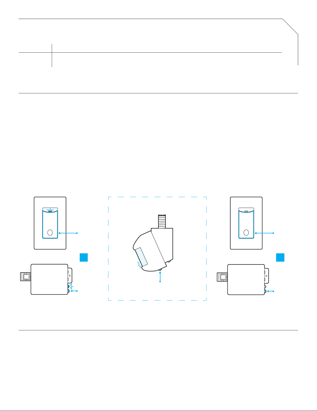
WIRELESS LINKING (PAIRING)
Linking a sensor with a wall switch controller or power pack is quickly done via the following procedure:
1. Enter pairing mode by holding down the wall switch controller’s (or power pack’s) button for 3 seconds until the LED starts alternating white then blue, then release.
2. At the sensor, hold down the programming button for 3 seconds until the LED starts alternating white then blue. Releasing will link the sensor with any device in pairing mode (see
note 1 below). The lights will toggle once as conrmation.
3. Repeat step 2 to link another sensor or device.
4. When all devices have been liked, close pairing mode on the wall switch controller (or power pack) by pressing the button 1 time. Pairing will also be automatically closed after 15
minutes of no new devices being linked.
Note 1: When in pairing mode, the alternating LED colors on the wall switch controller (or power pack) will periodically pause and blink out the total number of linked devices. There will
be no blinks during the pause until the rst device is linked.
ORDERING INFO
MODEL NUMBER DESCRIPTION
ILC-SWX-401-B
ILC-SWX-402-B
Wireless Wide View Sensor, PIR, 120°, Battery Powered
Wireless Hallway Sensor, PIR, Battery Powered
STEP 1
WALL SWITCH OR POWER PACK
STEP 2 & STEP 3
WIRELESS SENSOR
STEP 4
WALL SWITCH OR POWER PACK
ILC-SWX-401-B
HOLD
FOR 3 SEC
ILC-SWX-851
HOLD
FOR 3 SEC
ILC-SWX-950
HOLD
FOR 3 SEC
ILC-SWX-851
PRESS ONCE
ILC-SWX-950
PRESS ONCE
OR OR
FCC INFORMATION (FCC ID: 2AVRY-SWX0002)
INDUSTRY CANADA INFORMATION (IC: 26012-SWX0002)
This device complies with Part 15 of the FCC Rules. Operation is subject to the following conditions:
1. This device many not cause harmful interference, and
2. This device must accept any interference received, Including interference that may cause undesired operation
Changes and Modications not expressly approved by BLP Technologies can void your authority to operate this equipment under Federal Communications Commission’s rules.
This device complies with Industry Canada license-exempt RSS standard(s). Operation is subject to the following two conditions: (1) this device may not cause interference, and (2) this device
must accept any interference, including interference that may cause undesired operation of the device.
Le présent appareil est conforme aux CNR d’Industrie Canada applicables aux appareils radio exempts de licence. L’exploitation est autorisée aux deux conditions suivantes : (1) l’appareil ne
doit pas produire de brouillage, et (2) l’utilisateur de l’appareil doit accepter tout brouillage radioélectrique subi, même si le brouillage est susceptible d’en compromettre le fonctionnement.
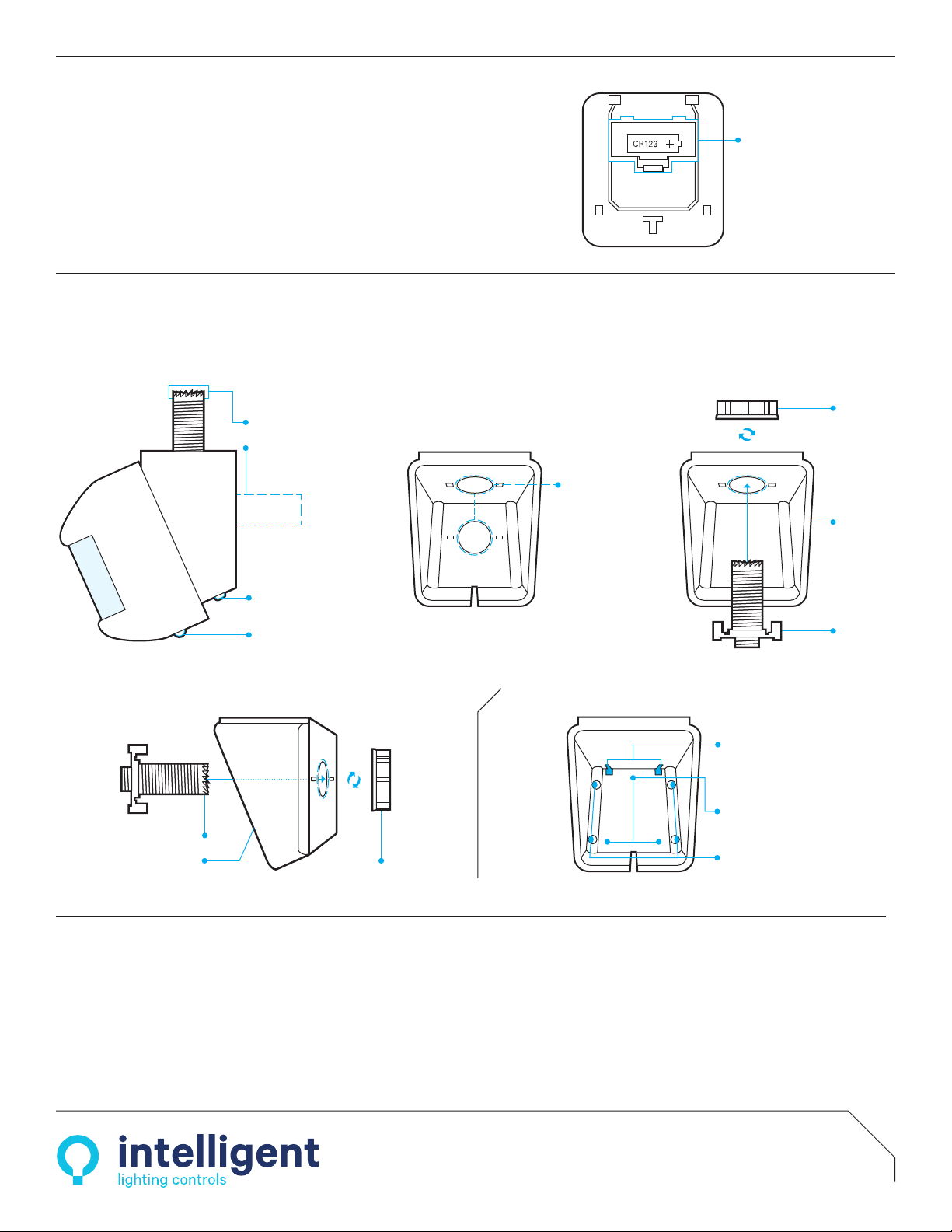
CHASE NIPPLE
SERRATED END FOR CUTTING
THROUGH CEILING TILE
ALTERNATE CHASE NIPPLE
REAR POSITION
SENSOR &
MOUNTING
BRACKET
LOCKING 3-POSITION
TILT ADJUSTMENT
PROGRAMMING
BUTTON
ADDITIONAL MOUNTING METHODS
SCREW HOLES FOR
MOUNTING TO FLAT WALL
CHANNELS FOR SLIDING
OVER MOUNTING SCREWS
SCREW HOLES FOR
MOUNTING IN CORNER
TOP INSTALLATIONMOUNTING WITH CHASE NIPPLE
RECOMMENDED
CHASE NIPPLE
LOCK NUT
MOUNTING
BRACKET
REAR INSTALLATION
CHASE NIPPLE
LOCK NUTMOUNTING BRACKET
CHASE NIPPLE & LOCK NUT INCLUDED FOR MOUNTING
TO CEILING TILE OR 1/2” KNOCKOUT IN JUNCTION BOX
TWO 1/2” TRADE SIZE
KNOCKOUTS FOR USE
WITH CHASE NIPPLE
OR DIRECT CONDUIT
CONNECTION
INSTALLATION OPTIONS
batteries are sold or from ILC
MOUNTING
BRACKET
CHASE NIPPLE
BATTERY
COMPARTMENT
BATTERY
COMPARTMENT
BATTERY
COMPARTMENT
LOCK NUT
CHASE NIPPLE
LOCK NUT
LOCKING 3-POSITION
TILT ADJUSTMENT
MOUNTING
BRACKET
LOCKING 3-POSITION
TILT ADJUSTMENT
SERRATED END
FOR CUTTING
THROUGH
CEILING TILE
SERRATED END FOR CUTTING
THROUGH CEILING TILE
BATTERY INFORMATION
ÃThe sensor runs on one CR123(A) Lithium Battery (included).
ÃInstall battery prior to mounting sensor. Polarity is indicated on the battery
compartment door.
ÃIf the sensor’s battery life reaches 10%, all wirelessly linked load controllers will
blink lights on/off/on upon initial occupancy as a replacement warning.
ÃReplacement batteries are available at most retailers or home centers where
Intelligent Lighting Controls | 5229 Edina Industrial Blvd. Edina, MN 5543
952.829.1900 | www.ilc-usa.com
© 2018 Intelligent Lighting Controls, Inc. All rights reserved.
Five-Year Limited Warranty
DATA400-B | REV 001–200608
Powered by SENSORWORX
This manual suits for next models
3


