Intelligent Motion Systems Excellence in Motion IM805H User manual

TM
intelligent motion systems, inc.
Excellence in MotionTM
IM483H & IM805H
HYBRID MICROSTEPPING DRIVERS
HFC-22 HEAT SINK/FAN/CLIP ASSEMBLY
IM483H-DK1 DEVELOPER’S KIT
PR-22 PIN RECEPTACLE CARRIER
OPERATING INSTRUCTIONS
370 N. MAIN ST., PO BOX 457, MARLBOROUGH, CT 06447
PH. (860) 295-6102, FAX (860) 295-6107
Internet: http://www.imshome.com, E-Mail: [email protected]
PATENT PENDING
TM
© Intelligent Motion Systems, Inc.
All Rights Reserved
IM483H/IM805H Operating Instructions
Revision R032206
The information in this book has been carefully checked and is believed to be
accurate; however, no responsibility is assumed for inaccuracies.
Intelligent Motion Systems, Inc., reserves the right to make changes without
further notice to any products herein to improve reliability, function or design.
Intelligent Motion Systems, Inc., does not assume any liability arising out of
the application or use of any product or circuit described herein; neither does it
convey any license under its patent rights of others. Intelligent Motion Systems
and are trademarks of Intelligent Motion Systems, Inc.
Intelligent Motion Systems, Inc.’s general policy does not recommend the use of
its products in life support or aircraft applications wherein a failure or malfunction
of the product may directly threaten life or injury. Per Intelligent Motion Systems,
Inc.’s terms and conditions of sales, the user of Intelligent Motion Systems, Inc.,
products in life support or aircraft applications assumes all risks of such use and
indemnies Intelligent Motion Systems, Inc., against all damages.
Change Log
Date Revision Changes
03/22/2006 R032206 Updated IMS Contact info, warranty and disclaimer info on cover

1
IM483H/IM805H Rev. R032206
Table of Contents
Section 1: Introduction.............................................................................. 4
The IM483H/IM805H Hybrid.......................................................................................... 4
Features and Benets ................................................................................................... 5
IM483H/IM805H .................................................................................................... 5
The Product Manual ...................................................................................................... 6
Hyperlinks.............................................................................................................. 6
Notes and Warnings...................................................................................................... 6
Section 2: Hardware Specications.......................................................... 7
Section Overview .......................................................................................................... 7
Mechanical Specications ............................................................................................. 7
Dimensional Information - IM483H/IM805H .......................................................... 7
Dimensional Information - PR-22 .......................................................................... 8
Electrical Specications................................................................................................. 9
IM483H DC Electrical Characteristics ................................................................... 9
IM805H DC Electrical Characteristics ................................................................. 10
IM483H/IM805H AC Electrical Characteristics.................................................... 11
Thermal Specications ................................................................................................ 11
Pin Assignment and Description ................................................................................. 12
IM483H/IM805H—Connector P1 ........................................................................ 12
IM483H/IM805H—Connector P2 ........................................................................ 13
Section 3: Mounting the IM483H/IM805H .............................................. 14
Section Overview ........................................................................................................ 14
Mounting the IM483H/IM805H .................................................................................... 14
Direct Mounting the IM483H/IM805H to a PC Board ......................................... 14
Mounting the IM483H/IM805H Using the PR-22 Receptacle ............................. 15
Recommended Mounting Hardware ................................................................... 16
Attaching the HFC-22 Heat Sink/Fan/Clip Assembly .......................................... 16
Removing the HFC-22 Heat Sink/Fan/Clip Assembly......................................... 17
Section 4: Theory of Operation .............................................................. 18
Section Overview ........................................................................................................ 18
Circuit Operation ......................................................................................................... 18
Microstep Select (MSEL) Inputs.................................................................................. 19
Stepping ...................................................................................................................... 19
Dual PWM Circuit ........................................................................................................ 20
Fullstep Output Signal ................................................................................................. 21
Timing.......................................................................................................................... 21
Section 5: Power Supply Requirements................................................. 22
Section Overview ........................................................................................................ 22
Selecting a Power Supply ........................................................................................... 22
Selecting a Motor Supply (+V) ............................................................................ 22
Recommended IMS Power Supplies .................................................................. 24
Selecting a +5VDC Supply.......................................................................................... 24
Recommended Wiring................................................................................................. 25
Rules of Wiring and Shielding ............................................................................. 25
AC Line Filtering.......................................................................................................... 26
Section 6: Motor Requirements.............................................................. 27
Section Overview ........................................................................................................ 27
Selecting a Motor ........................................................................................................ 27
Types and Construction of Stepping Motors ....................................................... 27
Sizing a Motor for Your System .......................................................................... 28
Recommended IMS Motors ............................................................................... 30

IM483H/IM805H Rev. R032206
2
3
IM483H/IM805H Rev. R032206
Motor Wiring ................................................................................................................ 32
Connecting the Motor .................................................................................................. 32
IM483H/IM805H .................................................................................................. 32
8 Lead Motors .................................................................................................... 33
6 Lead Motors ..................................................................................................... 34
4 Lead Motors ..................................................................................................... 35
Section 7: Interfacing to the IM483H/IM805H ........................................ 36
Section Overview ........................................................................................................ 36
Layout and Interface Guidelines.................................................................................. 36
Motor Power ................................................................................................................ 37
+5 VDC Input............................................................................................................... 38
Interfacing the Current Adjust Input............................................................................. 38
Determining the Output Current .......................................................................... 38
Setting the Output Current .................................................................................. 40
Current Adjust Resistor and Reference Values (IM483H) .................................. 41
Current Adjust Resistor and Reference Values (IM805H) .................................. 42
Reducing/Disabling the Output Current ............................................................. 43
Interfacing the IM483H/IM805H Inputs........................................................................ 44
The Microstep Resolution Select Inputs (MSEL) ................................................ 45
Interfacing the Fault Input ................................................................................... 46
Minimum Connections................................................................................................. 47
Section 8: Troubleshooting..................................................................... 48
Section Overview ........................................................................................................ 48
Basic Troubleshooting................................................................................................. 48
Problem Symptoms and Possible Causes .................................................................. 48
Contacting Application Support ................................................................................... 51
The IMS Web Site ....................................................................................................... 51
Returning Your Product to IMS ................................................................................... 51
Appendix A: The IM483H/IM805H Developer’s Kit ................................ 52
Section Overview ........................................................................................................ 52
Assembling the IM483H/IM805H-DK1 ........................................................................ 52
The INT-483H/IM805H Interface Board ...................................................................... 53
Pin Assignment and Descriptions ....................................................................... 54
Electrical Specications ...................................................................................... 54
Dimensional Information ..................................................................................... 55
Setting the Output Current ................................................................................. 56
Isolated Inputs..................................................................................................... 57
Microstep Resolution Settings............................................................................. 58
LED Indicators..................................................................................................... 59
Fault Protection ................................................................................................... 59
Full Step Output .................................................................................................. 59
Minimum Connections for the IM483H/IM805H-DK1 .................................................. 60

IM483H/IM805H Rev. R032206
2
3
IM483H/IM805H Rev. R032206
Figure 2.1: IM483H/IM805H Dimensions .................................................................. 7
Figure 2.2: PR-22 Dimensions ................................................................................... 8
Figure 2.3: IM483H/IM805H Connectors.................................................................. 13
Figure 3.1: PCB Hole Pattern .................................................................................. 14
Figure 3.3: PCB Hole Pattern for PR-22 Pin Receptacle Carrier ............................. 15
Figure 3.4: PCB Mounting ....................................................................................... 16
Figure 3.5: HFC-22 Exploded.................................................................................. 17
Figure 4.1: IM483H/IM805H Block Diagram .......................................................... 18
Figure 4.2: Recirculating PWM ................................................................................ 20
Figure 4.3: Non-Recirculating PWM ........................................................................ 20
Figure 6.1 A & B: Per Phase Winding Inductance .................................................. 29
Figure 6.2: 8 Lead Series Motor Connections ......................................................... 33
Figure 6.3: 8 Lead Parallel Motor Connections ....................................................... 33
Figure 6.4: 6 Lead Half Coil (Higher Speed) Motor Connections ............................ 34
Figure 6.5: 6 Lead Full Coil (Higher Torque) Motor ................................................. 34
Figure 6.6: 4 Lead Motor Connections .................................................................... 35
Figure 7.1: Power Interface ..................................................................................... 37
Figure 7.2: Current Adjust Resistor Connection ...................................................... 40
Figure 7.3: Setting the Output Current using an External Source ........................... 41
Figure 7.4: Reducing the Output Current ................................................................ 43
Figure 7.5: Current Reduction Interface .................................................................. 44
Figure 7.6: Input Pull-Up Resistors.......................................................................... 44
Figure 7.7: MSEL Inputs, Interface Example........................................................... 45
Figure 7.8: IM483H/IM805H Inputs .......................................................................... 46
Figure 7.9: Reset Timing .......................................................................................... 46
Figure 7.10: Interfacing the Fault In/Reset Inputs ...................................................... 46
Figure 7.11: Multiple Drives - One Reset ................................................................... 46
Figure A.1: IM483H/IM805H Developer’s Kit............................................................ 52
Figure A.2: HFC-22 Exploded................................................................................... 53
Figure A.3: INT-483H/805H Interface Board Dimensions......................................... 55
Figure A.4: INT-483H/805H Current Adjust and Reduction Resistor Placement...... 56
Figure A.5: INT-483H/805H Jumper Settings ........................................................... 57
Figure A.6: INT-483H/805H Opto-Isolated Inputs..................................................... 57
Figure A.7: INT-483H/805H MSEL Switch................................................................ 58
Figure A.8: INT-483H/805H Minimum Connections.................................................. 60
List of Figures
List of Tables
Table 2.1: IM483H DC Electrical Characteristics.......................................................... 9
Table 2.2: IM805H DC Electrical Characteristics........................................................ 10
Table 2.3: IM483H/IM805H AC Electrical Characteristics .......................................... 11
Table 2.4: IM483H/IM805H Thermal Specications ................................................... 11
Table 2.5: IM483H/IM805H Connector P1 Conguration ........................................... 12
Table 2.6: IM483H/IM805H Connector P2 Conguration ........................................... 13
Table 5.1: IM483H/IM805H Motor Power Supply Specications ................................ 23
Table 5.2: IM483H/IM805H +5VDC Power Supply Specication ............................... 24
Table 7.1: IM483H Current Adjust Resistor and Reference Values ........................... 41
Table 7.2: IM805H Current Adjust Resistor and Reference Values ........................... 42
Table 7.3: Motor Resolution Select Settings............................................................... 45
Table 7.4: IM483H/IM805H Minimum Connections .................................................... 47
Table A.1: INT-483H/805H Interface Board Pinout and Descriptions ......................... 54
Table A.2: INT-483H/805H Interface Board Electrical Characteristics........................ 54
Table A.3: INT-483H/805H Resolution Select Switch Settings ................................... 58

IM483H/IM805H Rev. R032206
4
5
IM483H/IM805H Rev. R032206
Section 1
Introduction
The IM483H/IM805H Hybrid
The IM483H/IM805H is a high performance, yet low cost microstepping driver
that utilizes advanced hybrid technology to greatly reduce size without sacric-
ing features. The IM483H/IM805H is exceptionally small, easy to interface and
use, yet powerful enough to handle the most demanding applications.
The IM483H/IM805H has 14 built-in microstep resolutions (both binary and
decimal). The resolution can be changed at any time without the need to reset
the driver. This feature allows the user to rapidly move long distances, yet
precisely position the motor at the end of travel without the expense of high
performance controllers.
With the development of proprietary and patented circuits, ripple current has
been minimized to reduce motor heating common with other designs, allow-
ing the use of low inductance motors to improve high speed performance and
system efciency.
The IM483H/IM805H, because of its ultra small size and low cost, can be used
to increase accuracy and smoothness in systems using higher step angle motors.
In many instances mechanical gearing can be replaced with microstepping,
reducing cost and eliminating potential maintenance.
Available as options for the IM483H/IM805H are the HFC-22 Heat Sink/Fan/Clip as-
sembly and the PR-22 Pin Receptacle carrier. The HFC-22 provides a unique cooling
solution and was designed specically for the IM483H and IM805H Hybrid Micro-
stepping Drivers. The HFC-22 will easily maintain a reliable rear plate temperature
without using large heat sinks and cumbersome mounting hardware. The heat sink
and fan are easily mounted to the driver by means of a removeable clip developed by
IMS. The HFC-22 fully assembled with the IM483H or IM805H takes up only 6.8 in3
of space! For applications where ease of removal is required, the PR-22 provides reli-
able, high quality receptacle set which comes attached to a high temperature plastic
throwaway carrier that allows for ease of placement for wave or hand soldering.
The IM483H/IM805H was developed to provide designers with affordable, state-of-
the-art technology for the competitive edge needed in today’s market.

IM483H/IM805H Rev. R032206
4
5
IM483H/IM805H Rev. R032206
Features and Benefits
IM483H/IM805H
n Very Low Cost.
n Ultra Miniature 2.10” x 2.60” x 0.362”
(53.34 x 66.04 x 9.19 mm).
n Advanced Hybrid Design.
n High Input Voltage (+12 to +48VDC/+24 to +75 VDC).
n High Output Current (3A RMS, 4A Peak/5A RMS, 7A Peak).
n No Minimum Inductance.
n FAULT Input and Output.
n Phase to Phase Short Circuit Protection.
n Over-Temperature Protection.
n Microstep Resolution to 51,200 Steps/Rev.
n Microstep Resolutions can be Changed “On-The-Fly” With-
out Loss of Motor Position.
n 20 kHz Chopping Rate.
n Automatically Switches Between Slow and Fast Decay for
Unmatched Performance.
n 14 Selectable Resolutions both in Decimal and Binary.
n Adjustable Automatic Current Reduction.
n At Full Step Output.
n Optional Cooling Solution (HFC-22).
n Optional Receptacle Carrier (PR-22).
IM483H/IM805H Rev. R032206
6
7
IM483H/IM805H Rev. R032206
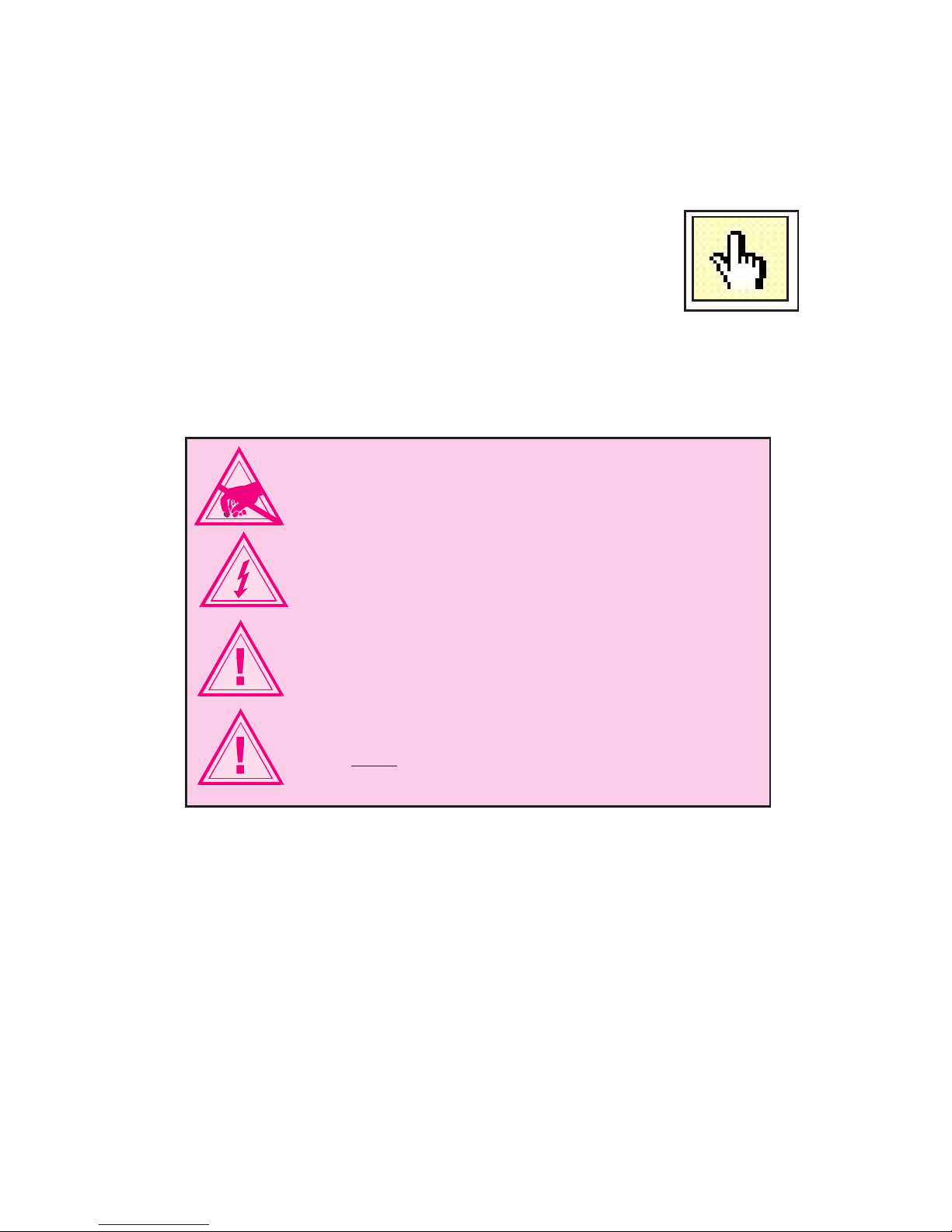
The Product Manual
The IM483H/IM805H product manual in its electronic format may be down-
loaded from the IMS website at http://www.imshome.com. This version includes
a Bookmarks feature that allows the reader to link from a Bookmarked Topic
in the Table of Contents to a full description of that feature’s
attributes and functions. You can also select a Topic directly
from the Table of Contents Pages. Topics with a hyperlink
function are further identiable because the cursor changes
from a normal pointer to a “nger” pointer when placed over
the word.
Notes and Warnings
WARNING! The IM483H/IM805H components are sensitive to
ElectroStatic Discharge (ESD). All handling should be done at an
ESD protected workstation.
WARNING! Hazardous voltage levels may be present if using an
open frame power supply to power the IM483H/IM805H.
WARNING! Ensure that the power supply output voltage does not
exceed the maximum input voltage of the IM483H/IM805H.
WARNING! Do not apply power to the IM483H/IM805H without
proper heat sinking or cooling! The included thermal pad
(TN-22)MUST be used between the IM483H/IM805H and the
heat sink! The maximum rear plate temperature of the IM483H/
IM805H is 70°C!
IM483H/IM805H Rev. R032206
6
7
IM483H/IM805H Rev. R032206
Section 2
Hardware Specifications
Section Overview
This section will acquaint you with the dimensional information, pin descrip-
tion, power, environmental and thermal requirements of the IM483H/IM805H.
It is broken down as follows:
n Mechanical Specications.
n Electrical Specications.
n Thermal Specications.
n Pin Assignment and Description.
Mechanical Specifications
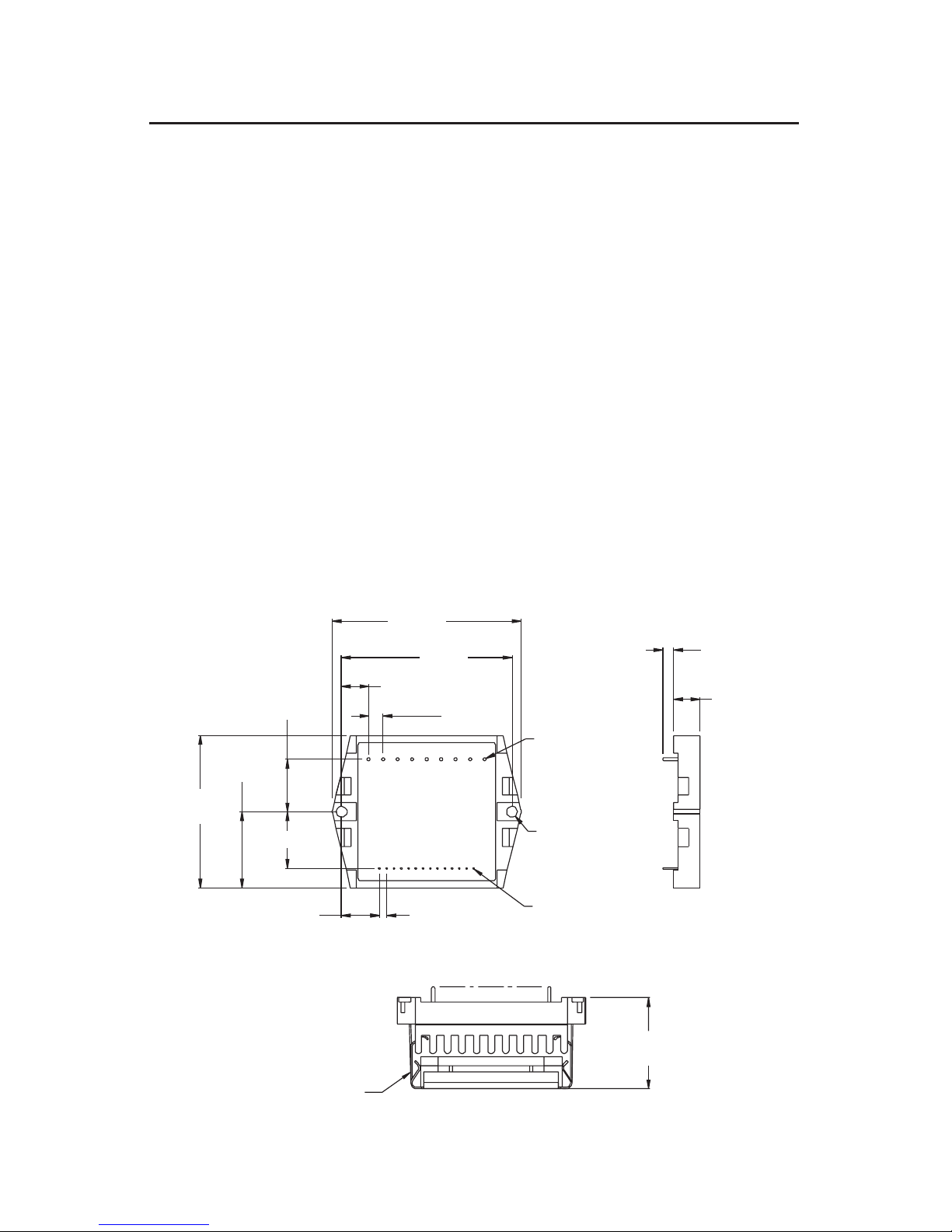
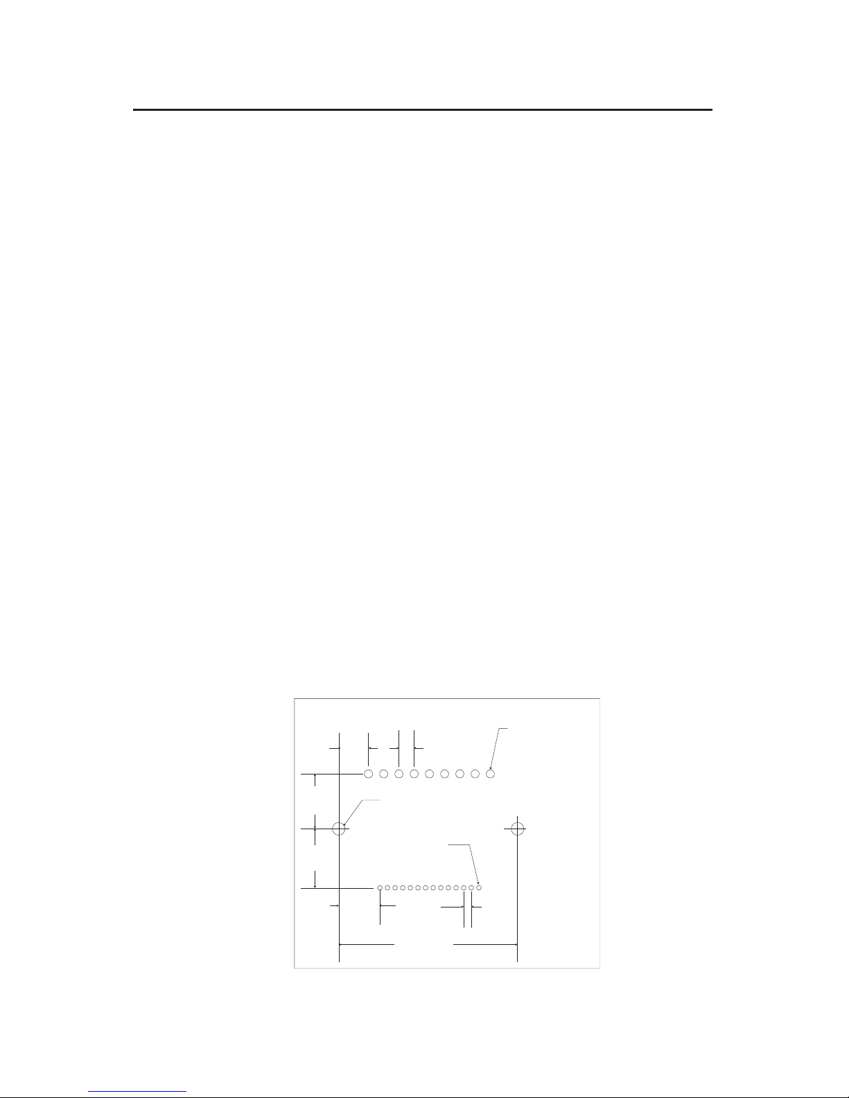
Dimensional Information - IM483H/IM805H
Dimensions are in inches, parenthesis dimensions are in millimeters.
Figure 2.1: IM483H/IM805H Dimensions
HEATSINK/FAN/CLIP ASSY
1.25
(31.75)
.525
(13.34)
13 X .100
(2.54)
.025 DIA. PIN
(0.64 DIA PIN)
.045 DIA. PIN
(1.14 DIA. PIN)
2X .150 DIA. THRU
(3.81 DIA. THRU)
2.100
(53.34)
.780 (19.81)
1.050
(26.67)
.720
(18.29)
1
14
1
9P2
P1
.375
(9.52)
8 X .200
(5.08)
2.350
(59.69)
2.600
(66.04)
23 X .156
(3.96)
.362
(9.19)

IM483H/IM805H Rev. R032206
8
9
IM483H/IM805H Rev. R032206
Figure 2.2: PR-22 Dimensions
2.800
(71.12)
0.115
(2.92)
1.700
(43.18)
0.290
(7.36)
0.200
(5.08)
0.100
(2.54)
1.300
(33.02)
1.500
(38.10)
.072 DIA.
(1.83 DIA.)
.055 DIA.
(1.40 DIA.)
.090
(2.28)
.230
(5.84)
.118 DIA.
(3.00 DIA.)
.100 DIA.
(2.50 DIA.)
.050
(1.27)
.050
(1.27)
.117
(2.97)
.255
(6.48) .290
(7.36)
.290
(7.36)
IMS
PR-22
IM483H/IM805H Rev. R032206
8
9
IM483H/IM805H Rev. R032206
Electrical Specifications
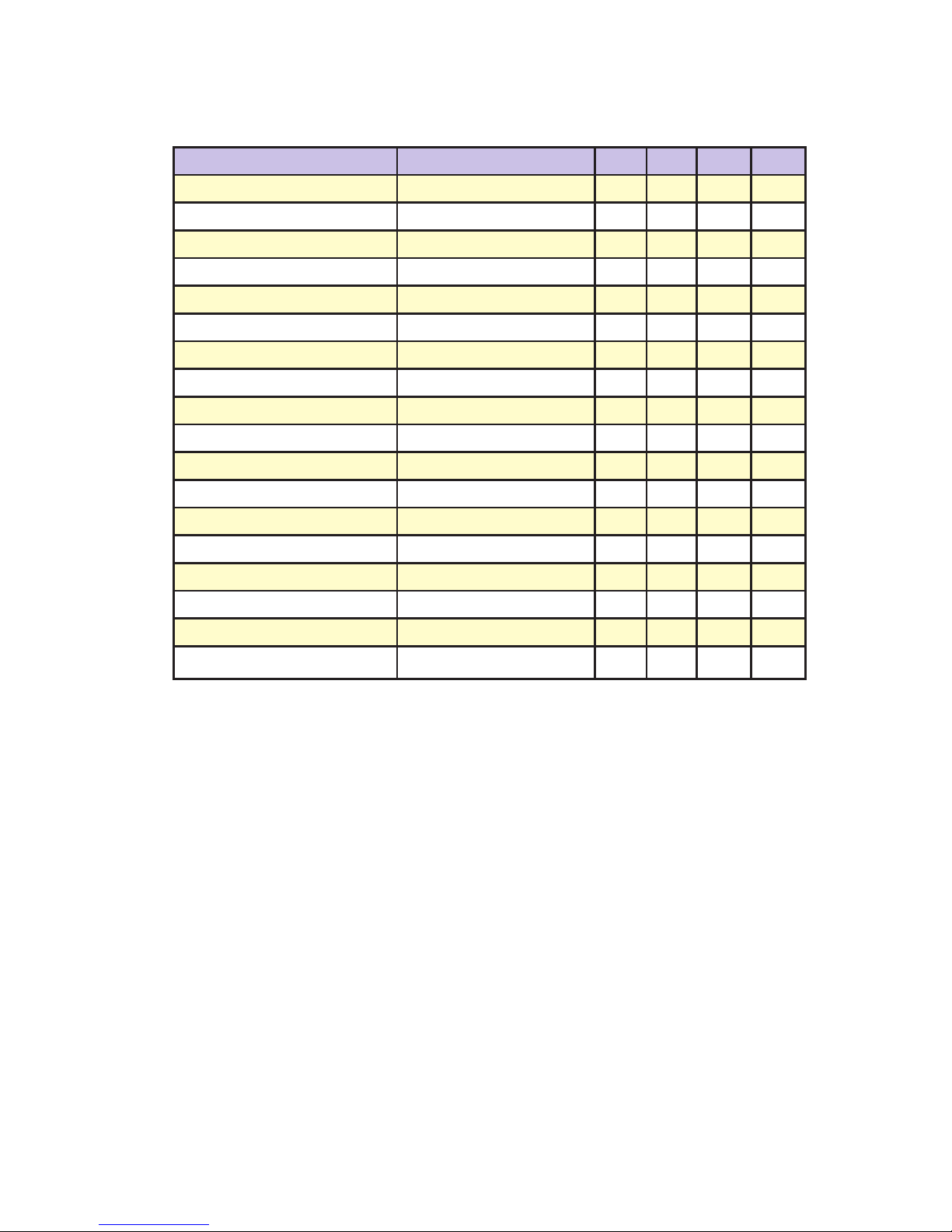
IM483H DC Electrical Characteristics
*Includes Motor Back EMF.
**Lower Currents may be used for Current Reduction.
Table 2.1: IM483H DC Electrical Characteristics
Specification Test Condition Min. Typ. Max. Unit
Input Voltage +12 +45 +48* VDC
Phase Output Current RMS 0.4** 3 A
Phase Output Current Peak 4 A
Supply Current (+5V) Inputs/Outputs Floating 100 mA
Active Power Dissipation IOUT=3A RMS 50 80 mA
Low Level Input Voltage All Inputs 0.8 V
High Level Input Voltage All Inputs Except Reset 2.0 V
High Level Input Voltage Reset 2.3 V
Low Level Input Current SCLK,DIR,H/F, Enable -1.2 mA
Input Pull-Up Resistance Fault, MSEL 0-3, Enable 4.94 4.99 5.03 kΩ
Input Pull-Up Resistance Step Clock, Direction 2.19 2.21 2.23 kΩ
Input Pull-Up Resistance Reset Input Only 1.27 kΩ
Low Level Output Current Fault, Fullstep -6 mA
High Level Output Current Fault, Fullstep 3 mA
Low Level Output Voltage Fault, Fullstep 0.4 V
High Level Output Voltage Fault, Fullstep 4.5 V
Fan Operating Voltage 4.3 5.0 5.7 V
Fan Operation Current 170 mA
IM483H/IM805H Rev. R032206
10
11
IM483H/IM805H Rev. R032206
IM805H DC Electrical Characteristics
Table 2.2: IM805H DC Electrical Characteristics
*Includes Motor Back EMF.
**Lower Currents may be used for Current Reduction.
Specification Test Condition Min. Typ. Max. Unit
Input Voltage +24 +45 +75* VDC
Phase Output Current RMS 1** 5 A
Phase Output Current Peak 5 A
Supply Current (+5V) Inputs/Outputs Floating 100 mA
Active Power Dissipation IOUT=3A RMS 50 80 mA
Low Level Input Voltage All Inputs 0.8 V
High Level Input Voltage All Inputs Except Reset 2.0 V
High Level Input Voltage Reset 2.3 V
Low Level Input Current SCLK,DIR,H/F, Enable -1.2 mA
Input Pull-Up Resistance Fault, MSEL 0-3, Enable 4.94 4.99 5.03 kΩ
Input Pull-Up Resistance Step Clock, Direction 2.19 2.21 2.23 kΩ
Input Pull-Up Resistance Reset Input Only 1.27 kΩ
Low Level Output Current Fault, Fullstep -6 mA
High Level Output Current Fault, Fullstep 3 mA
Low Level Output Voltage Fault, Fullstep 0.4 V
High Level Output Voltage Fault, Fullstep 4.5 V
Fan Operating Voltage 4.3 5.0 5.7 V
Fan Operation Current 170 mA
IM483H/IM805H Rev. R032206
10
11
IM483H/IM805H Rev. R032206
Thermal Specifications
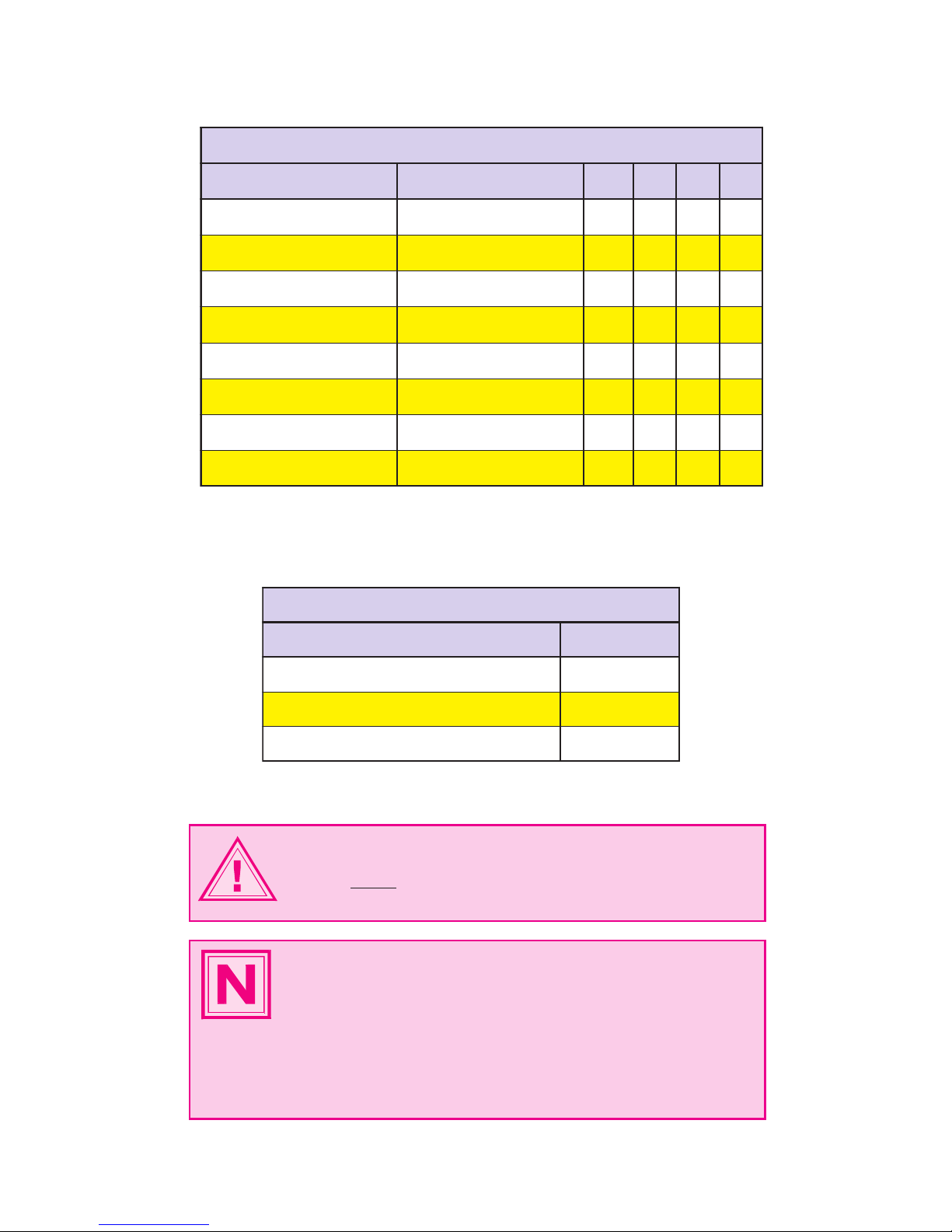
IM483H/IM805H AC Electrical Characteristics
scitsiretcarahClacirtcelECAH508MI/H384MI
noitacificepS noitidnoCtseT
niM
pyT
xaM
tinU
htdiWesluPteseR 0.1 µS
emiTputeSnoitceriD,LESM
001 Sn
htdiWesluPkcolCpetS 05 Sn
emiTnoitucexEkcolCpetS egnahCLESMronoitceriDoN
001
Sn
emiTnoitucexEkcolCpetS egnahCLESMronoitceriD 002 Sn
tuptuOpetS-lluFotkcolCpetS
57
Sn
ycneuqerFtupnIkcolCpetS 01 zHM
ycneuqerFreppohCMWP
02
zHk
Table 2.3: IM483H/IM805H AC Electrical Characteristics
)C°(snoitacificepSlamrehTH384MI
noitacificepS
egnaR
erutarepmeTtneibmA °05+ot°0
erutarepmeTegarotS
°521+ot°04-
erutarepmeTetalPmumixaM °56+
Table 2.4: IM483H/IM805H Thermal Specications
WARNING! Do not apply power to the IM483H/IM805H without
proper heat sinking or cooling! The included thermal pad
(TN-22) MUST be used between the IM483H/IM805H and the
heat sink! The maximum rear plate temperature of the IM483H/
NOTE: Care should be taken when choosing a heat sink to
ensure that there is good thermal ow, otherwise hot spots may
occur in the IM483H/IM805H which will reduce the effectiveness
of the thermal protection.
NOTE: An optional cooling fan assembly (Part # HFC-22) is
available for the IM483H/IM805H.
IM483H/IM805H Rev. R032206
12
13
IM483H/IM805H Rev. R032206
Pin Assignment and Description
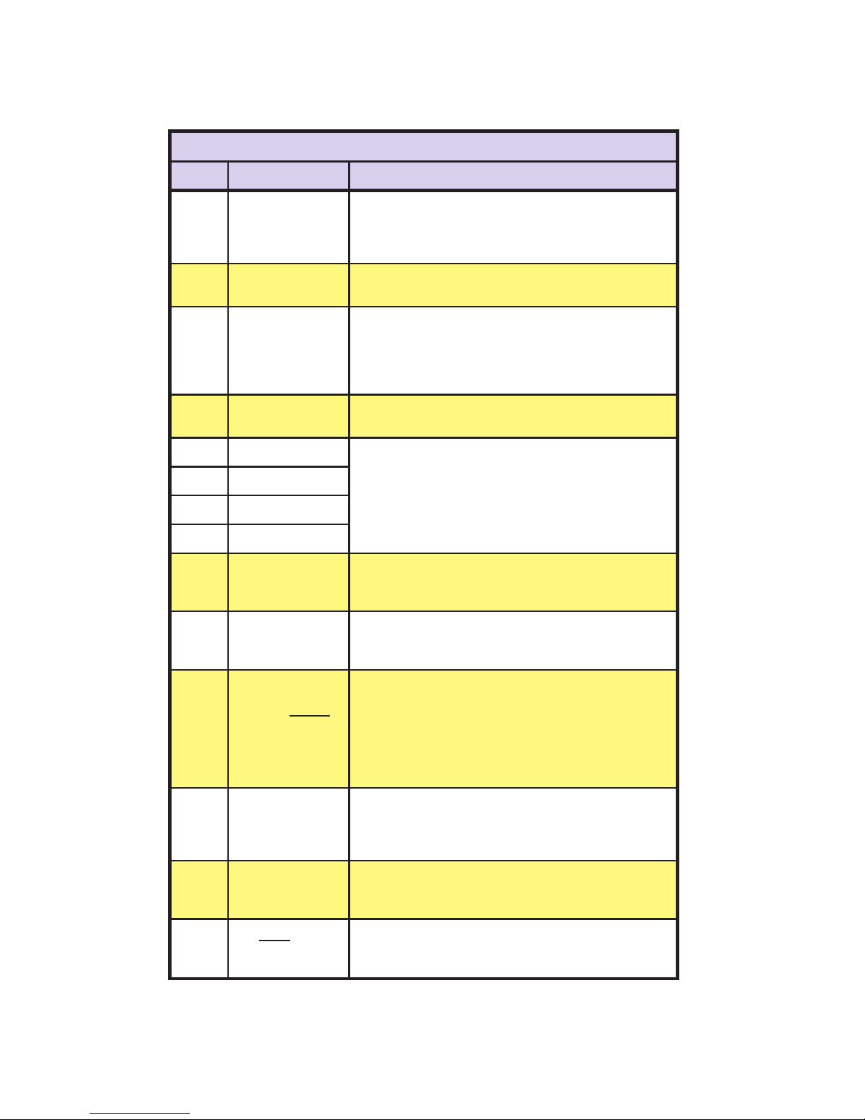
Table 2.5: IM483H/IM805H Connector P1 Conguration
CH508MI/H384MI noitarugifnoC1Protcenno
#NIP NOITCNUF
SLIATED
1ecnerefeRtnerruC
tuptuO
sirotsiserA.tuptuOecnerefeRtnerruCesahP
dnatuptuoecruostnerrucAm1sihtneewtebdetcennoc
egatlovecnereferehtetarenegot)4:2P(nipdnuorgeht
.rotomehtnitnerrucesahpkaepehttesotdesu
2
tnemtsujdAtnerruC
tupnI
otdeilppaegatlovA.tupnItnemtsujdAtnerruCesahP
.rotomehtnitnerrucesahpkaepehtstestupnisiht
3noitcudeRtnerruC
tupnItsujdA
rotsiserA.tupnItnemtsujdAnoitcudeRtnerruCesahP
ehttesotdesufi,2:1Pdnanipsihtneewtebdetcennoc
ehtecuderyletanoitroporplliw,tnerrucesahprotom
sdnoces5.yletamixorppasgnidniwrotomhtobnitnerruc
.tupnikcolcpetsehtfoegdeevitisoptsalehtretfa
4
tupnItluaF
dehctalaetareneglliwtupnisihtnolangisWOLcigolA
.noitidnocTLUAF
50tceleSnoituloseR
ehttcelesotdesU.stupnItceleSnoituloseRpetsorciM
stupniesehT.rotomehtfopetsrepspetsorcimforebmun
PIDaotdetcennocebdluohsdnapu-dellupyllanretniera
nanotuptuoLTTro)NPN(gniknisrotcellocnepo,hctiws
.rellortnocytrapdrihtroSMI
61tceleSnoituloseR
72tceleSnoituloseR
83tceleSnoituloseR
9
tupnIkcolCpetS
rotomehtsecnavdatupnisihtnoegdegniogevitisopA
tnadnepedsitnemercniehtfoezisehT.tnemercnieno
.stupnitcelesnoituloserehtfosgnittesehtnopu
01 tupnInoitceriD
.rotomehtfonoitceridehtegnahcotdesusitupnisihT
fonoitcennocehtnopusdnepedoslanoitceridlacisyhP
.sgnidniwrotomeht
11 elbasiD/elbanE
tupnI
fonoitcestuptuoehtelbasid/elbaneotdesusitupnisihT
,etats)detcennocton(HGIHcigoLaninehW.revirdeht
ehtelbasidlliwtupnisihtgnikniS.delbaneerastuptuoeht
petsehttibihnitonseodtupnisiht,revewoH.tuptuorevird
forebmunehtybetadpulliwstuptuoeht,erofereht,kcolc
sawtielihwrevirdehtotdeilppa)ynafi(seslupkcolc
.delbasid
21 tuptuOpetS-lluF-nO
lluftadenoitisopsirevirdehtnehwsetacidnituptuosihT
llufforebmunehttnuocotdesuebnactuptuosihT.pets
forebmunehtfosseldrager,devomsahrotomehtspets
.HGIHevitcasituptuosihT.neewtebnispetsorcim
31
tuptuOtluaF
noitidnoctiucrictrohsarehtietahtsetacidnituptuosihT
tluafehtnodetcetedsawlangisWOLaroderruccosah
.HGIHevitcasituptuosihT.tupni
41 tupnIteseR
stuptuoesahp(revirdehtteserlliwtupnisiht,WOLnehW
laitinistitaeblliwrevirdeht,desaelernehW.)elbasidlliw
.)NOBesahP,FFOAesahP(etats
IM483H/IM805H Rev. R032206
12
13
IM483H/IM805H Rev. R032206
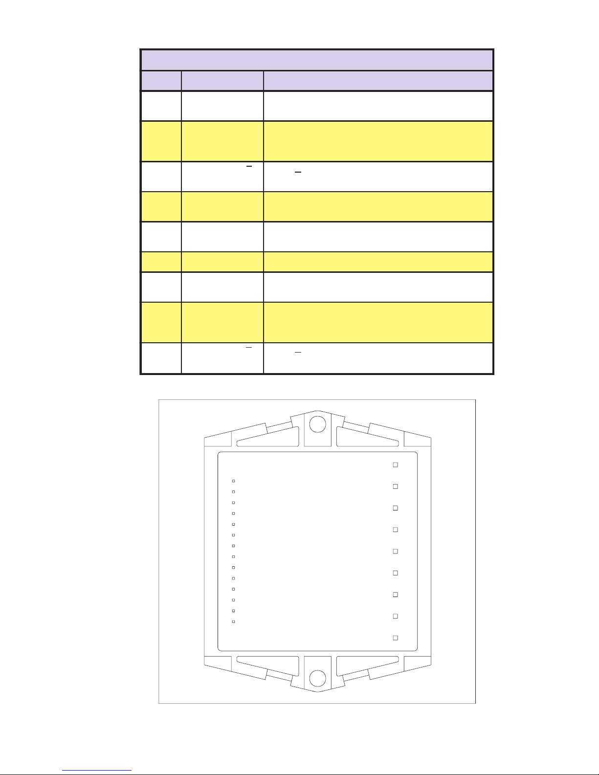
Table 2.6: IM483H/IM805H Connector P2 Conguration
Pin 1
Pin 1
P1 P2
Figure 2.3: IM483H/IM805H Connectors
CH508MI/H384MI noitarugifnoC2Protcenno
#NIP NOITCNUF SLIATED
1BesahProtoM
tuptuO .3nipdnanipsihtneewtebdetcennocsiBesahP
2
BDNG
ebdluohsdnuorgsihT.dnuorGBesahProtoM
roticapaclanretxeehtfodael”dnuorg“ehtotdetcennoc
.BesahProf
3BesahProtoM
tuptuO .1nipdnanipsihtneewtebdetcennocsiBesahP
4
DNG
ylppusrewopehtfo,nruterro,dnuorgehT.dnuorGrewoP
.erehdetcennocsi
5V+ ,H384MIehtrofCDV84+ot21+.egatloVylppuSrotoM
.H508MIehtrofCDV57+ot42+
6
tupnIV5+
.egatlovylppuscigolCDV5+
7AesahProtoM
tuptuO .9nipdnanipsihtneewtebdetcennocsiAesahP
8ADNG
ebdluohsdnuorgsihT.dnuorGAesahProtoM
roticapaclanretxeehtfodael”dnuorg“ehtotdetcennoc
.AesahProf
9AesahProtoM
tuptuO .7nipdnanipsihtneewtebdetcennocsiAesahP
Bottom View
IM483H/IM805H Rev. R032206
14
15
IM483H/IM805H Rev. R032206
Section 3
Mounting the IM483H/IM805H
Section Overview
This section covers mounting the IM483H/IM805H in your system. The fol-
lowing mounting options are covered:
n Mounting the IM483H/IM805H to a PCB.
n Mounting the IM483H/IM805H using the PR-22 Pin Re-
ceptacle.
n Recommended Mounting Hardware.
n Attaching/Removing the HFC-22 Heat Sink/Fan/Clip As-
sembly.
Mounting the IM483H/IM805H
The IM483H & IM805H hybrids are designed to be soldered into the users PC
board, however, they may also be mounted using the PR-22 pin receptacle car-
rier for ease of removal.
Direct Mounting the IM483H/IM805H to a PC
Board
The IM483H and IM805H hybrids are designed to be soldered directly into a PC board.
The following diagram contains the hole pattern and recommended pad sizes for direct
mounting of the IM483H/IM805H.
Recommended Soldering Practices
Max. Soldering Temp .................................................................... 315°C
Max. Soldering Time .....................................................................10 sec.
Figure 3.1: PCB Hole Pattern (Direct Mounting of the IM483H/IM805H to a PC Board)
0.200
(5.08)
0.100
(2.54)
0.375
(9.5)
0.525
(13.30)
2.350
(59.70)
0.720
(18.3)
0.780
(19.8)
0.166 (4.2) DIA. HOLE
2 PLACES
0.70 (1.80) DIA. HOLE
0.150 (3.80) DIA. PAD
9 PLACES
0.042 (1.00) DIA. HOLE
0.075 (1.90) DIA. PAD
14 PLACES

IM483H/IM805H Rev. R032206
14
15
IM483H/IM805H Rev. R032206
Recommended Solder Recommended Cleaning Solvent
Kester “245” No Clean Tech Spray “Envirotech 1679”
Alpha Metals “Telecore Plus” Chemtronics “Flux-off NR 2000”
Multicore “X39B” No Clean
Figure 3.3: PCB Hole Pattern (for Mounting of the PR-22 Pin Receptacle Carrier)
Mounting the IM483H/IM805H Using the PR-22
Receptacle
The PR-22 pin receptacle carrier allows
for easy placement of multi-ngered
receptacle pins facilitating easy removal
and placement of the IM483H/IM805H
driver. The PR-22 is a disposable plastic
frame containing 23 receptacles in a
layout that matches the pin layout of the
IM483H/IM805H hybrid.
This tool enables the user to insert the
23 receptacles into their PC board design
in a single operation for wave or hand
solder. The plastic frame can then be
lifted out and discarded. The following
gure (Figure 3.3) shows the PCB hole pattern and recommended pad size that should be
used on the end-user PC board. The recommended mounting hardware are the same as
illustrated in Figure 3.4.
To lift the disposable carrier after soldering, gently pry the carrier from the PCB with a
at head screwdriver or, to avoid chancing PC board damage, use the optional pry bar
(PB-22).
0.200"
(5.08)
0.100"
(2.54)
0.375
(9.5)
0.525”
(13.30)
2.350"
(59.70)
0.720
(18.3)
0.780
(19.8)
0.166 (4.2) DIA. HOLE
2 PLACES
0.107 (2.72) DIA. HOLE
0.156 (3.96) WIDE PAD
0.176 (4.47) LONG PAD
9 PLACES
0.062 (1.57) DIA. HOLE
0.090 (2.29) WIDE PAD
0.110 (2.79) LONG PAD
14 PLACES
Figure 3.2: PR-22 Pin Receptacle Carrier

IM483H/IM805H Rev. R032206
16
17
IM483H/IM805H Rev. R032206
Attaching the HFC-22 Heat Sink/Fan/Clip Assembly
The gure at right illustrates the HFC-22 mounted to the IM483H/IM805H. To
attach the HFC-22 complete the following:
1) Placing the heat sink on the driver, align so that the dot on
the heat sink is on the same side as the dot on the driver,
with the TN-22 thermal pad sandwiched between them.
2) Insert two of the arms from the fan/clip assembly into the
corresponding slots in the driver, aligning the curved ngers
on the clip between the posts of the heat sink. Insert the
other two locking tabs into the opposite slots and snap into
place. The locking tabs on all four arms should be complete-
ly through the slots on the driver.
Recommended Connector
The HFC-22 fan connector plugs into the following pin header:
Molex Part Number: 22-23-2021
Digikey Part Number: WM-4200-ND
Samtec Part Number: TSW-101-07-T-D
NOTE! The torque specication for the mounting screws
is 5.0 to 7.0 lb-in (0.60 to 0.80 N-m). Do not over tighten
screws!
Figure 3.4: PCB Mounting Hardware (Direct Mounting or Socketed)
Recommended Mounting Hardware
The following gure (Figure 3.4) illustrates the recommended mounting hardware. This
hardware and associated torque specication will be the same whether the PR-22 pin
receptacle carrier is used or the driver is directly mounted to a PC Board.
METRIC.
U.S.
Phillips Pan HD
#6 Stainless
Mach. Screw
Phillips Pan HD
M3 X 0.5 Stainless
Mach. Screw
#6 Split Lock Washer
Stainless (.04TH, .24OD)
M3 Split Lock Washer
Stainless (.08TH, 6.20 Dia. Max)
M3 Flat Washer
Stainless (.05TH, 6.20 Dia. Max)
#6 Flat Washer
Stainless (.04TH, .24OD)
Keystone #4866 or
equivalent #6 threaded
insert (Mounted from
bottom of PCB
PEM #KFS2-M3 or
equivalent M3 X 0.5 threaded
insert (Mounted from
bottom of PCB
WARNING! The IM483H/IM805H Drivers are not
hermetically sealed. DO NOT wash the PCB with the
Driver soldered in place. Always wash the PCB prior to
mounting the Driver. NEVER use compressed air.

IM483H/IM805H Rev. R032206
16
17
IM483H/IM805H Rev. R032206
Removing the HFC-22 Heat Sink/Fan/Clip Assembly
To remove the HFC-22 from the the driver:
1) Squeeze the two arms on one side of the assembly until the
locking tabs are free in the slot on the drive.
2) Gently lift the freed side away from the drive. The HFC-22 will
separate from the drive. (The fan will be locked inside the
clip.)
Figure 3.5: HFC-22 Heat Sink/Fan/Clip Assembly
NOTE! If the curved ngers do not align between
the posts on the heat sink do not try and force them.
Verify that the heat sink is sitting square on the driver
and that the dot on the heat sink is on the same side
as the dot on the driver!
WARNING! The heat sink mounting surface must be a
smooth, at surface with no burrs, protrusions, cuttings or
other foreign objects.
NOTE! Be certain to remove the clear protective sheet
from the TN-22 Thermal Pad before installation.
FINGERS
CLIP
FAN
HEAT-SINK
THERMAL
PAD
DRIVER
ARM
LOCKING TAB

IM483H/IM805H Rev. R032206
18
19
IM483H/IM805H Rev. R032206
Section 4
Theory of Operation
Section Overview
This section will cover the circuit operation for the IM483H/IM805H micro-
stepping driver hybrid.
n Circuit Operation
n Microstep Select Inputs
n Stepping
n Dual PWM Circuit
n Fullstep Output
n Timing
Circuit Operation
Microstepping drives have a much higher degree of suitability for applications
that require smooth operation and accurate positioning at low speeds than do
half/fullstep drivers and reduction gearing. The IM483H/IM805H, with its
ability to be set to microstep resolutions as high as 51,200 microsteps/rev (256
Microsteps/step) using a 1.8° stepping motor, is ideal for such applications.
In order to subdivide motor steps into microsteps while maintaining positional
accuracy, precise current control is required. The IM483H/IM805H accom-
plishes this by the use of a unique Dual PWM circuit built into the patented
IM2000 Microstep Controller ASIC, which resides at the heart of the IM483H/
IM805H. This PWM circuit uses an alternating recirculating/non-recirculating
mode to accurately regulate the current in the windings of a two phase stepping
motor.
Figure 4.1: IM483H/IM805H Block Diagram
This manual suits for next models
1
Table of contents
Other Intelligent Motion Systems DC Drive manuals


Popular DC Drive manuals by other brands

Phoenix Mecano
Phoenix Mecano OKIN REFINED CB3633A Product Instruction

YASKAWA
YASKAWA H6R B Series manual

Trane
Trane VarioTrane TR1 2800 Series operating instructions

Simu
Simu T5 AUTOSHORT BHz Original instructions

Becker
Becker E22 Assembly and operating instructions

Wittenstein Alpha
Wittenstein Alpha SP Series operating manual


Allen-Bradley
Allen-Bradley Series B Service manual

Leadshine Technology
Leadshine Technology EM556S user manual

Festo
Festo DRQD Series operating instructions

YASKAWA
YASKAWA J1000 CIMR-JC series user guide

gefran
gefran AGy-L Series Installation and commissioning manual

Leadshine Technology
Leadshine Technology DM542E user manual