Intelligent LLEVO-W User manual
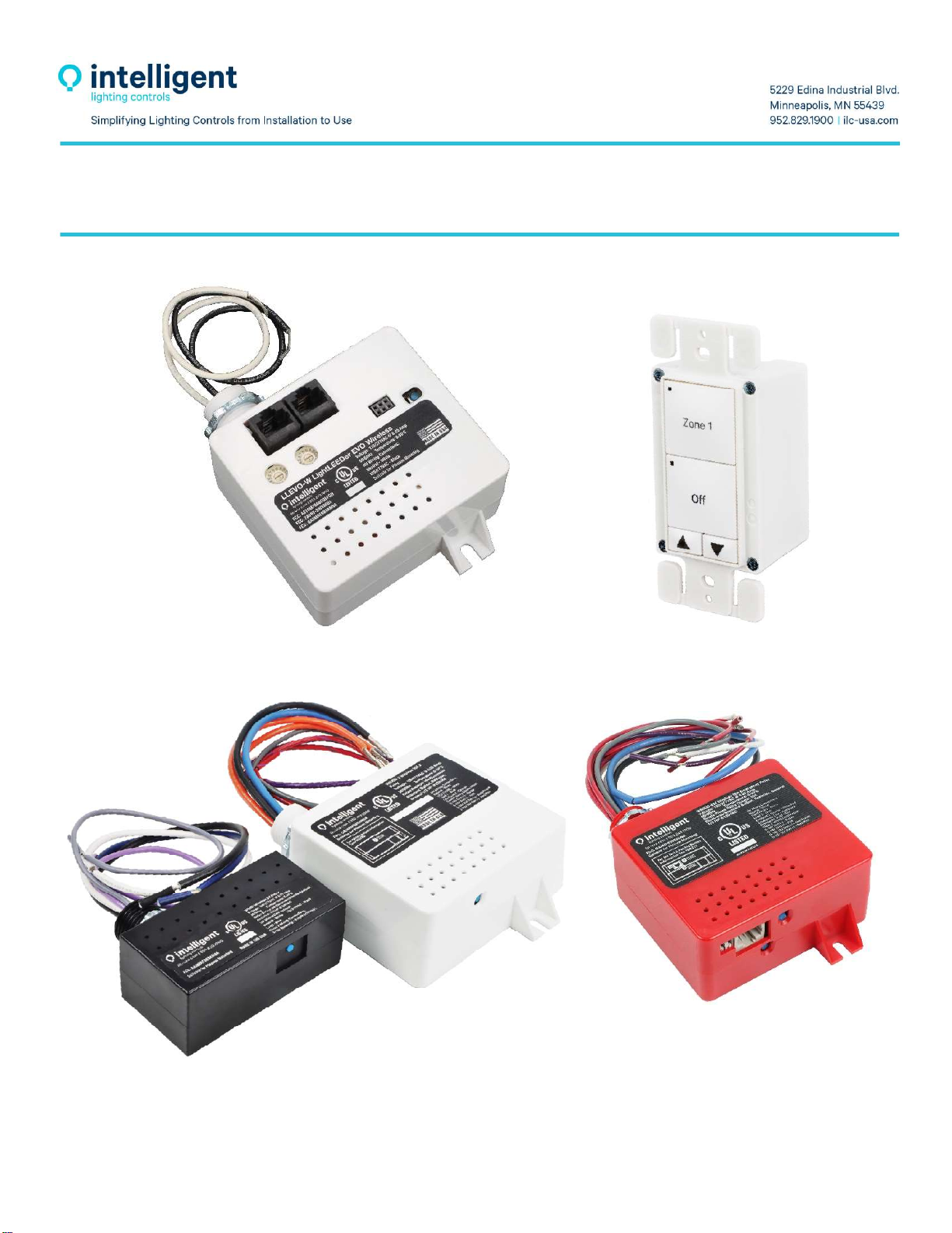
LightLEEDer Wireless
LLEVO-W LSG3-W
WR5D WR20D and WR20D-2 WR20D-EM

Page1of25
LightLEEDer Wireless
User Guide
Revision A
8-25-2022
FCC Device Statement
This device complies with part 15 of the FCC Rules.
Operation is subject to the following two conditions;
(1) This device may not cause harmful interference, and
(2) this device must accept any interference received,
including interference that may cause undesired operation.

Page2of25
TableofContents
Section1LightLEEDerWirelessProductDescription
1.0Overview
1.1LightLEEDerEVOWirelessController
1.1.1Features
1.2WirelessRelays
1.2.1Features
1.3WirelessEmergencyRelay
1.3.1Features
1.4LightSyncG3Wireless
1.4.1Features
Section2LightLEEDerWirelessProductandWiringDetails
2.0Overview
2.1LLEVO‐WDetails
2.2WR5D,WR20D,WR20D‐2Details
2.2.1WR5DDetails
2.2.2WR20DandWR20D‐2Details
2.3WR20D‐EMDetails
2.3.1WR20D‐EMWiringDetails
2.4LSG3‐WDetails
Section3LightLEEDerWirelessProductInstallation
3.0Overview
3.1LLEVO‐WInstallation
3.2WR5D,WR20D,WR20D‐2Installation
3.2.1WR5D
3.2.2WR20DandWR20D‐2
3.3WR20D‐EMInstallation
3.4LSG3‐WInstallation

Page3of25
Section4DirectLinkControlOperations
4.0Overview
4.1RecommendedProcedureforInstallationandLinkingDevices
4.2ActivateDirectLinkModeataLSG3‐WWirelessSwitch
4.3LinkWR5D,WR20D&WR20D‐EMRelay
4.4LinkaWR20D‐2Relay
4.4.1LinktoLoad1(Relay‐1/Dimmer‐1)
4.4.2LinktoLoad2(Relay‐2/Dimmer‐2)
4.5ClearallSettingsintheRelay’sLinkMemory
4.6DirectLinkNotes
Section5WirelessEVOConfiguration
5.0Overview
5.1RecommendedProcedureforInstallationandLinkingDevicestoLLEVO‐W
5.2ClearAllSettingsintheRelay’sDirectLinkMemory
5.3LL‐ProandLL‐ProNetworkConfigurationSoftware
5.4ExampleLinkProgramming

Page4of25
Section1LightLEEDerWirelessProductDescription
1.0Overview
TheILCLightLEEDerWarlessproductsprovideboththeabilitytobe“DirectLinked”forstand‐aloneoperationina
singleofficeornetworkedusingaLightLEEDerEVO‐Wcontrollerthatcancontrolmultiplespaces.TheLightLEEDer
productlineincludestheLLEVO‐Wcontroller,theWR5D5Ampsingleloadrelaywithdimming,theWR20Dand
WR20D‐2thatareboth20Amploadratedwithdimmingforaoneortwoindependentloads,theWR20D‐EMdevice
thathasa20Ampratedrelaywithdimmingforthenormalpowerloadandincludesanintegrated20Amprated
Emergencyrelaywithdimmingoutputallinasinglepackage.
1.1LightLEEDerEVOWirelessController
TheLightLEEDerEVO‐Wirelesscontroller(LLEVO‐W)isadistributedlightingcontrolpanelthatsimplifiesinstallation
andconnectswithILCwirelessrelays,LSG3‐Wswitches,occupancy,andphotocellsensors.TheLLEVO‐Wcontroller
providesallthesamecontroloptionsasastandardwiredEVOcontroller,withtheenhancedwirelessradioconnection
toinputsandoutputs.
1.1.1 Features
MadeinUSA
915Mhzradiocommunicationwith50‐footlineofsitedistance
Distributedlightingcontroller
DigitalCAT‐5connectiontoILCpanelnetwork
Linkupto64wirelessrelays
Linkupto64wirelessLSG3‐Wswitchesorsensors
PushbuttonwithstatusLEDtosweeprelays
StandaloneornetworkedwithanyLightLEEDercontroller
Timeclockincludes7/365‐daycalendar,DaylightSavingsTime,Astronomic,Open/Close
RJ45connectorsfornetworkingwithotherLightLEEDerpanels
Enclosure,suitableforplenummounting
1.2WirelessRelays
TheLightLEEDerWirelessRemoteRelaysaredesignedtobemountedatthepowerjunctionboxorlightingfuturefor
directcontrolofthelightingload.Wirelessrelayscomewith0‐10Vdimmingandareavailablea5Amp1‐load,20Amp
1‐load,or20Amp2‐loadconfigurations.Therelaysutilizelatchingcontactsforlowpowerconsumptionandarerated
forhandlinghighLEDinrush.Communicationisdoneoverthe915MHzradiofrequency,andallowsforbothdirectlink
andnetworkedapplications.

Page5of25
1.2.1 Features
MadeinUSA
WirelessRemoterelayswith915MHzradiocommunications
5AmpWR5Drelaywithdimming
20AmpWR20DandWR20D‐2relaywithdimmingforlightingloadsor20AmpPlug‐load
Latchingrelayholdspositionwithoutpresenceofpower,savingenergy
Directmountingatpowerjunctionboxorlightfixturewith1/2”K.O.mounting
DirectlinkandrelaycontrolbuttonwithstatusLED
6”Wireleadsforline/loadanddimmingconnections
600Vratedwireallows0‐10Vinhighvoltagecompartment
Isolated0‐10VDimmingcontrol
1.3WirelessEmergencyRelay
TheILCRemote20Amp,EmergencyBypassRelaycombinesnormalrelayoperationwithaUL924bypassrelayinone
convenientpackage.Relaysareavailableinbothawireless(WR20D‐EM)version,andahardwiredversion(R20D‐EM).
TheWR20D‐EMcommunicateswitha915MHzradiowithotherILCwirelessdevices.Whennormalpowerislost,the
EMrelaywillautomaticallyforceONtheEMloadandsenddimmingto100%.Whennormalpowerisrestored,the
devicewillreturntonormalcontrol.TheWR20D‐EMrelayhasatestbuttonandawiredinputthatcanbeusedfora
remotetestswitch,orasanoverrideconnectionfromaFirealarmsystem.
1.3.1Features
MadeinUSA
UL924rated
EMRelayratedupto20Amp@120/277VAC
NormalRelayratedupto20Amp@120/277VAC
EMLoadfollowoperationofnormalloadcontrol
Testbuttonforlocaltestoperation
OverrideInputforremoteemergencytestswitchorfirealarmsystemoverride
Plenumrated
Directmountingatpowerjunctionboxorlightfixturewith1/2”K.O.

Page6of25
1.4LightSyncG3Wireless
TheLightSyncDigitalG3WirelessSwitch(LSG3‐W)canconnecttoILCwirelessrelaysindirectlinkmodeortothe
LLEVO‐Wirelesscontrollerfornetworking.TheLSG3‐WisprovidedinallthestandardG3switchtypes.TheMZDand
SceneswitchdimmingbuttonssupportPress‐and‐HoldRamp‐Up/Ramp‐Downdimming.Holdingazonebuttononan
MZDwillallowausertoselectthatzoneforindividualdimming.Scenebuttonssetadimmingscene,holdingthescene
buttonwillcapturethecurrentdimmerlevelstothescene.TheScene/MZDcomboswitchprovidebothoperationsin
onedevice.LSG3‐WdigitalswitchstationsprovidecontrolofwirelessrelaysandwiredrelaysovertheILCnetwork
whenlinkedtoanEVO‐WcontrollerintheILCnetwork.
1.4.1Features
MadeinUSA
Digital915Mhzradiocommunicationwith50‐footlineofsightrange
10Yearlithiumbattery
DirectLinktowirelessrelaysornetworkedwithEVO‐Wcontroller
UniqueIDradiotransmitcodeperswitchstation
Wirelessswitchstationforcontrolofanyrelay,groupofrelays,dimmers,scene,
orpreset
Non‐Dim1to7buttoncontrolconfigurations
MZD‐Multi‐ZoneDimmingforupto6zoneswithAll‐Off
SceneSwitchwithdimmingforupto5sceneswithOff
Scene/Multi‐Zonewithdimmingcomboforupto4Scene'sorZone's
(2S/4Z,3S/3Zor4S/2Z)
SceneCaptureoperationforallstationswithscenebuttons
PressandHolddimmingoperationwithraiseandlowerbuttonsforramp‐up
andramp‐downdimming
Laserengravingisprovided,andcustomengravingisavailable
BlackandRedbuttonstationsarepad‐printed
ColorChangeKitavailableforWhite,Ivory,Gray,RedandBlack
InternalConfigurationcanbechangedattheswitch
Decora®stylesingle‐gangswitchplateavailableuponrequest
Page7of25
Section2LightLEEDerWirelessProductandWiringDetails
2.0Overview
WhenwiringtheWirelessdevicesalwaysobservestandardNECcoderequirementsformakinglinevoltageandclass‐2
lowvoltageconnections.Reviewtheproductdetailandwiringdetailinformationbelowbeforeinstallingproduct.
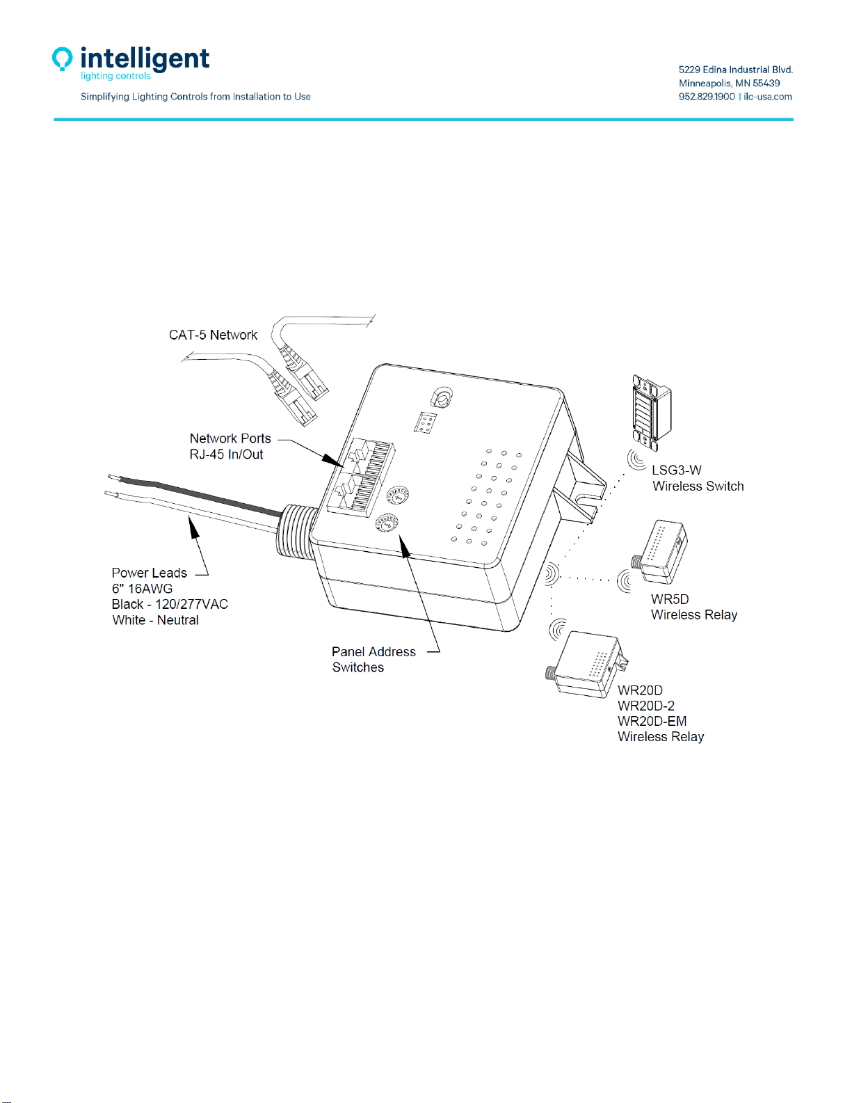
2.1LLEVO‐WDetails
WiretheLightLEEDerEVOWirelesscontrollerto120or277VAC
powerwithinrangeofthewirelessdevicestobecontrolled.
WirelessdevicesarelinkedtotheLLEVO‐Wcontrollerusing
a915Mhzradiosignalwithina50‐footlineofsightrange.
ConnectCAT‐5datacablefromtheILCdatanetworkandsetthepaneladdressswitchesfor
networkingtheLLEVO‐Wcontroller
Refertonetworklayoutforpaneladdressinformation.
LinktheremoteLSG3‐WswitchesandwirelessrelaystotheLLEVO‐Wcontroller
tocreateawirelesspanelsystem.

Page8of25
2.2WR5D,WR20D,WR20D‐2,WR20D‐EMDetails
2.2.1WR5DDetails
Mountonjunctionboxwith½”knockoutordirectlytofixture
TheWR5DWirelessRelaysisdesignedforuptoa5Ampload.
ConnectallLine/LoadandNeutralwires,plus0‐10VDCcontrolwiresasshownabove,
capallunusedleads.
PresstheWirelessLink/Testbuttontotoggletherelay,LEDstatusshouldlightgreenforrelayon.
TheWR5DcandirectlinktoLSG3‐WswitchesortotheLLEVO‐Wfornetworking.
Electrical: OperatingEnvironment: WireColorGuide:
1LoadwithDimming Location:Interior Neutral=White
5Amps,120/277VACLED/ElectronicOperatingTemp:0‐50deg.C LineInput=Black
5Amps,120/277VACTungsten Humidity:10‐90%Non‐Condensing LoadOutput=Blue
1/4HP@120VACMotorLoad Atmosphere:Non‐Explosive/Corrosive0‐10VDC(+)=Purple
50mASinkfor0‐10VDimming Vibration:Stationary 0‐10VDC(‐)=Pink
600VACrateddimmingleads


Page10of25
Mountonjunctionboxwith½”knockoutandsecurestowallwithmountingbracket.
TheWR20DWirelessRelaysisdesignedforuptoa20Amploadperrelay.
ConnectallLine/LoadandNeutralwires,plus0‐10VDCcontrolwiresasshownabove,
capallunusedleads.
PresstheWirelessLink/Testbuttontotoggletherelay,LEDstatusshouldlightgreenfor
relayon.
TheWR20DcandirectlinktoLSG3‐WswitchesortotheLLEVO‐Wfornetworking.
Electrical: OperatingEnvironment:
1or2LoadIndependentwithDimming Location:Interior
16Amps,120/277VACLED/Electronic OperatingTemp:0‐50deg.C
20Amps,120/277VACTungsten Humidity:10‐90%Non‐Condensing
1/4HP@120VACMotorLoad Atmosphere:Non‐Explosive/Corrosive
100mASinkfor0‐10VDimming Vibration:Stationary
600VACrateddimmingleads
PlugLoadCompatible
WireColorGuide:
Neutral(Load1)=White
Line1,Input=BlackLine2,Input=Orange/Black
Load1,Output=BlueLoad2,Output=Orange
Load1,0‐10VDC(+)=Purple Load2,0‐10VDC(+)=Orange/Purple
Load1,0‐10VDC(‐)=Pink Load2,0‐10VDC(‐)=Orange/Pink
Page11of25
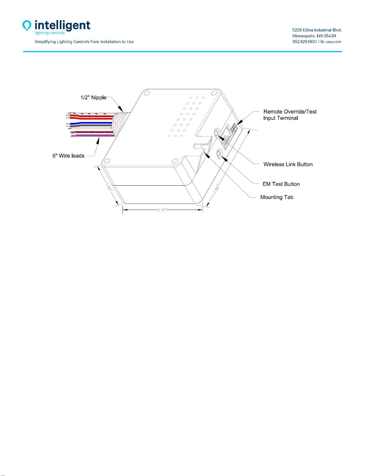
2.3WR20D‐EMDetails
Mountonjunctionboxwith½”knockoutandsecurestowallwithmountingbracket.
TheWR20D‐EMWirelessRelaysisdesignedforuptoa20Amploadperrelay.
ThisDevicewillbesuppliedbytwopowersourcesfromnormalandemergencypower
circuits,turnoffbothcircuitsatthebreakerbeforeconnectingthewiresorservicingthe
device.
ConnectallLine/LoadandNeutralwires,plus0‐10VDCcontrolwiresasshownabove,
capallunusedleads.
TestInputforatestswitch,Fire,orsecurityinterface.Theinputacceptsatwowire
nonpolarized10‐28VDC/VACat10mAmaximum.
PresstheWirelessLink/Testbuttontotoggletherelay,LEDstatusshouldlightgreen
forrelayon.
TheWR20D‐EMcandirectlinktoLSG3‐WswitchesortotheLLEVO‐Wfornetworking.
Electrical: OperatingEnvironment:
2LoadIndependentEmergencyandNormal
PowercontrolwithDimming Location:Interior
16Amps,120/277VACLED/Electronic OperatingTemp:0‐50deg.C
20Amps,120/277VACTungsten Humidity:10‐90%Non‐Condensing
1/4HP@120VACMotorLoad Atmosphere:Non‐Explosive/Corrosive
100mASinkfor0‐10VDimming Vibration:Stationary
600VACrateddimmingleads
UL924EMandUL916Normalloadrated
Page12of25
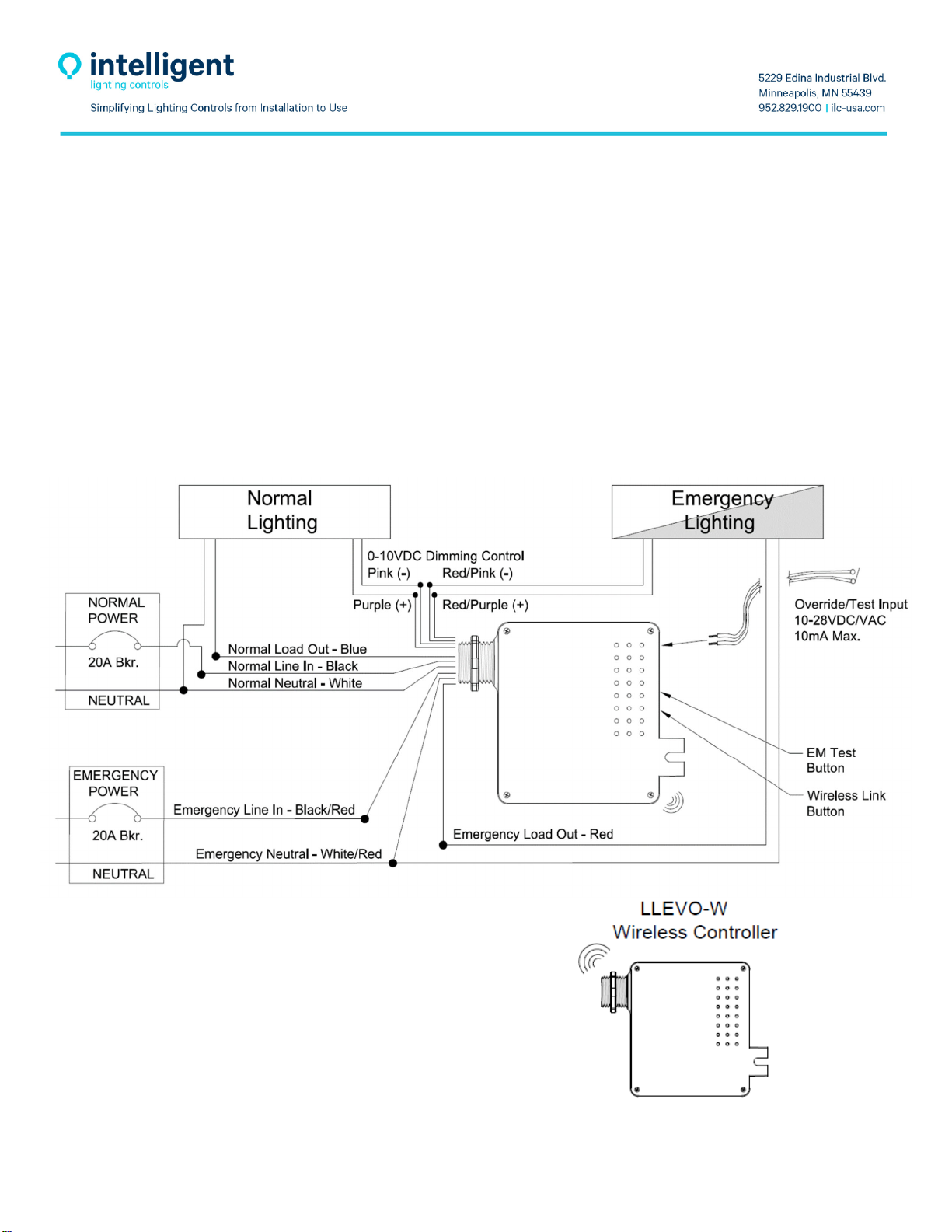
WireColorGuide:
EmergencyPowerWire:NormalPowerWire:
Neutral=White/RedNeutral=White
LineInput=Black/RedLineInput=Black
LoadOutput=RedLoadOutput=Blue
Dimming0‐10VDC(+)=Red/Purple Dimming0‐10VDC(+)=Purple
Dimming0‐10VDC(‐)=Red/Pink Dimming0‐10VDC(‐)=Pink
TheWR20D‐EMRelaycombinesbothnormalandemergencypoweredlightingcontrolinthesamedevice.Bothloads
operatetogetherundernormalconditions,whennormalpowerislosttheEmergencyloadand0‐10Vdimmingare
forcedON.
2.3.1WR20D‐EMWiringDetails

Page13of25
TheWR20D‐EMrelayispoweredbytwoelectricalcircuits,verifythat
bothcircuitbreakersareOFFbeforeconnecting.
ConnecttheEmergencypowerlineandloadwiresasshownabove.
ConnecttheNormalpowerlineandloadasshownabove.
KeeptheEmergencyandNormalpowerseparateperNECcoderequirements.
Connectall0‐10VDCcontrolwiresasshownabove,capallunusedleads
PresstheEmergencytestbuttontoforceanemergencystatetest.
Connectanyremotetestswitchesorconnectionsfromafirealarm
systemandtesttheoperation
TheWR20D‐EMcandirectlinktoLSG3‐WswitchesortotheLLEVO‐Wfornetworking
Caution:TheWR20D‐EMdevicesarefeedfromtwoindependentelectricalcircuits.Whenservicing,confirmthatboth
circuitbreakersareswitchedOFFtopreventaccidentalharm.
IMPORTANTSAFEGUARDS
Whenusingelectricalequipment,basicsafetyprecautionsshouldalwaysbefollowedincludingthefollowing:
DoNotuseoutdoors
Donotmountneargasorelectricheaters
Equipmentshouldbemountedinalocationandataheightwhereitwillnotbesubjecttotamperingby
unauthorizedpersonnel
Theuseofaccessoryequipmentnotrecommendedbythemanufacturermaycauseanunsafecondition
Donotusetheequipmentforotherthanitsintendeduse
Allserviceshouldbeperformedbyqualifiedpersonnel
READANDFOLLOWALLSAFETYNSTRUCTIONS
SAVETHESEINSTRUCTIONS

Page14of25
2.4LSG3‐WDetails
Standardsinglegangmounting. OperatingEnvironment:
UniqueIDfactoryset Location:Interior
Wireless915Mhzcommunication OperatingTemp:0‐50deg.C
Lithiumbatteryprovided(CR123A) Humidity:10‐90%Non‐Condensing
MountingscrewsprovidedAtmosphere:Non‐Explosive/Corrosive
Vibration:Stationary
LightSyncG3Wirelessswitchesareavailableinallstandardswitchconfigurations
Page15of25
Section3LightLEEDerWirelessProductInstallation
3.0Overview
TheLightLEEDerWirelessproductusea915MHzradiosystemforcommunicationsupportinga50”lineofsight
distancebetweendevices.WheninstallingalwaysbeawareofandavoidotherequipmentthatmayproduceRFnoise
thatcouldinterferewiththeILCradiocommunication.DoNotinstallthedeviceswhereasteelstructurelikeventilation
ductsmayblockorreducesignalstrength.Alwaysinstallthedevicesinaneasytoaccesslocation.
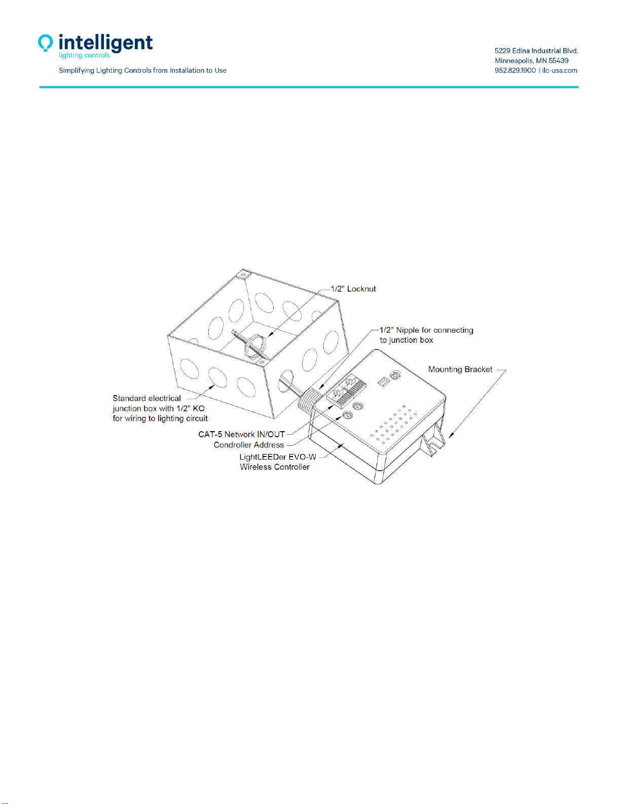
3.1LLEVO‐WInstallation
MounttheremoteLLEVO‐Wwirelesscontrollerinaneasytoaccesslocation,
typically,atthepowerjunctionboxcentrallylocatedtotheareatobecontrolled.
ForbestperformancealwaysplacetheLLEVO‐Wwhereitsradioisnotobstructedbymetalenclosuresor
subjecttoequipmentwithhighEMFnoise.
VerifythattheLLEVO‐Wiswithin50feetlineofsighttoallswitchstations
andrelaysintendedtobelinkedtothecontroller.
MounttheLLEVO‐Wtothejunctionboxusingthe1/2"nippleandsecurethecontrollerusingthe1/2"locknut
providedandmountingbracket.
Terminatethelinevoltagelightingcircuit120or277VACpowerleadstothecontrollerasrequiredbyNEC
Code.
RunCAT‐5datacablefromtheILCpanelnetworktotheLLEVO‐WcontrollerIn/Outportstoaddthiscontroller
tothesystem.
Setthecontroller'suniqueaddress(2‐digitHEX)andrecordforfuturereference.
TheLLEVO‐Wcanbeprogrammedforstand‐aloneornetworkoperationfrom
theILCnetworksystem,refertoLL‐Prosoftwareinstructions.
TolinktheLightLEEDerwirelessrelaysandLightSyncG3wirelessswitches
totheLLEVO‐WcontrollerrefertoTB0402.

Page16of25
3.2WR5D,WR20D,WR20D‐2Installation
3.2.1WR5D
MounttheremotemountWR5Drelayinaneasytoaccesslocation,typicallydirectlyontheexteriorofthe
fixtureoratthepowerjunctionboxfeedingthefirstlightfixturetobecontrolled.
Forbestperformancealwaysmounttherelaywhereitsradioisnotobstructed
bymetalenclosuresorsubjecttoequipmentwithhighEMFnoise.
Verifythattherelayiswithin50feetlineofsighttotheswitchstationsintended
tocontrolitandthatradiotransmissionisnotobstructedbymetalbarriers.
Mounttherelaytoexteriorofthefixtureorlinevoltagejunctionboxusingthe
1/2"nippleandsecuretherelayusingthe1/2"locknutprovided.
Terminatethelinevoltage120/277VACpower,neutralandfixtureloadoutput
leadsfromtherelaytotheloadwiresasrequiredbyNECCode.
Test0‐10VDCwiringfromthefixtureforpropervoltageandreversewiringoftheDCcontrolleadsbefore
connectingtotheWR5Drelay.
Terminatethelowvoltage0‐10VDCdimmingcontrolleads(Purple/Pink)usingtwo18AWGwiretoanyremote
fixtures,keepClass‐2wiringseparatefromlinevoltagerunsperNECcoderequirements.
TestrelayforON/OFFoperationusingtheTest/Linkbuttonontherelay.
ToLinktherelaytoaLightSyncG3wirelessswitchesrefertoTB0401and
tolinktherelaytoaLLEVO‐WwirelesscontrollerrefertoTB0402.

Page17of25
3.2.2W20DandWR20D‐2
Mountremotemountrelayinaneasytoaccesslocation,typicallyatthepowerjunctionboxfeedingthefirst
lightfixturetobecontrolled,ordirectlyintothefixturelinevoltagewiringcompartment.
Forbestperformancealwaysmounttherelaywhereitsradioisnotobstructedbymetalenclosuresorsubject
toequipmentwithhighEMFnoise.
Verifythattherelayiswithin50feetlineofsighttotheswitchstationsintendedtocontrolitandthatradio
transmissionisnotobstructedbymetalbarriers.
Mounttherelaytojunctionboxorfixtureusingthe1/2"nippleandsecuretherelayusingthe1/2"locknut
providedandmountingbracket.
Terminatethelinevoltage120/277VACpower,neutraland fixtureloadoutputleadsfromtherelaytothe
loadwiresasrequiredbyNECCode,capofftheunusedleads.
IfusingtheWR20D‐2relayterminatethe2ndloadcontrolwirestothe2ndfixtureorplugloadasrequiredby
NECCode,capofftheunusedleads.
Test0‐10VDCwiringfromthefixtureforpropervoltageandreversewiringoftheDCcontrolleadsbefore
connectingtotheWR20DorWR20D‐2relay.
Terminatethelowvoltage0‐10VDCdimmingcontrolleads(Purple/Pink)usingtwo18AWGleads.KeepClass‐2
wiringseparatefromlinevoltagerunsperNECCoderequirements.
TestrelayforON/OFFoperationusingtheTest/Linkbuttonontherelay.
TolinktherelaytoaLightSyncG3wirelessswitchesrefertoTB0401andtolinktherelaytoaLLEVO‐W
wirelesscontrollerrefertoTB0402.

Page18of25
3.3WR20D‐EMInstallation
Mounttherelayinaneasytoaccesslocation,typicallyatthepower
voltagewiringcompartment.
ThisEmergencyrelayshouldbeinstalledwhereitcanbefrequentlytestedforEMoperation,refertolocal
coderequirementsforperiodictesting.
TheWirelessEMRelay(WR20D‐EM)shouldbemountedwheretherelaysradiocommunicationisnot
obstructedbymetalenclosuresorsubjecttoequipmentwithhighEMFnoise.
TheWR20D‐EMrelaymustbewithin50feetlineofsighttotheswitchstationsintendedtocontrolitandthat
radiotransmissionisnotobstructedbymetal.
Mounttherelaytoajunctionboxorfixtureusingthe1/2"nippleandsecurewiththe1/2"locknutprovided
andmountingbracket.
TerminatetheEmergencyandNormalpowerlineinputs120/277VAC,neutrals,andfixturecontrolload
outputsfromtherelaytotheEMandNormalpowerfixturestobecontrolledasrequiredbyNECCode.
Test0‐10VDCwiringfromthefixturesforpropervoltageandpolarityoftheDCcontrolleadsbefore
connectingtotheWR20D‐EMrelay.
TerminatethelowvoltageClass‐20‐10VDCdimmingcontrolleadsusingtwo#18AWGleadsforEMand
Normalcontroltothefixtures.KeepClass‐2wiringseparatefromlinevoltagerunsperNECCode
requirements.
TesttheEMrelayoperationusingtheEMTestbuttonontherelay.
TolinktheWR20D‐EMrelaytoLSG3‐Wswitches,refertoTB0401
ForcontroloftheWR20D‐EMfromaLLEVO‐WcontrollerrefertoTB0402.

Page19of25
3.4LSG3‐WInstallation
InstallingtheLSG3‐WSwitch:
InstallremotemountLightSyncG3WirelessswitchwithinradioproximityofthewirelessrelayorLLEVO‐W
controlleritwillbelinkedto.
ForbestperformancealwaysmounttheLSG3‐Wswitchwheretheradioisnotobstructedbymetalenclosures
orsubjecttoequipmentwithhighEMFradionoise.Plasticlowvoltageclass‐2enclosuresorswitchmounting
bracketsarerecommendedifallowedbycode,alongwithaplasticcoverplate.
MountLSG3‐Wswitchinstandard1‐gangswitchbracketorjunctionboxusingscrewsprovided.
Verifythattheswitchstationiswithin50feetlineofsighttothewirelessrelayorLLEVO‐Wcontrolleritis
intendedtobelinkedto.
BeforeinstallingLSG3‐Wswitch,openbatterydoorandinstalltheprovidedbattery.Thewirelessswitchwill
automaticallyenterlinkmode,refertoTechnicalBulletinTB0401forwirelessrelaydirectlinkdirections.
TolinktheLSG3‐WswitchtoaLLEVO‐WwirelesscontrollerrefertoTechnicalBulletinTB0402.
This manual suits for next models
5
Table of contents


