IntelliQuilter HQ-AVANTE 03.25.16 User manual
1
INTELLIQUILTER INSTALLATION ON HQ-AVANTE W. PROFESSIONAL TABLE
Version 03.25.16
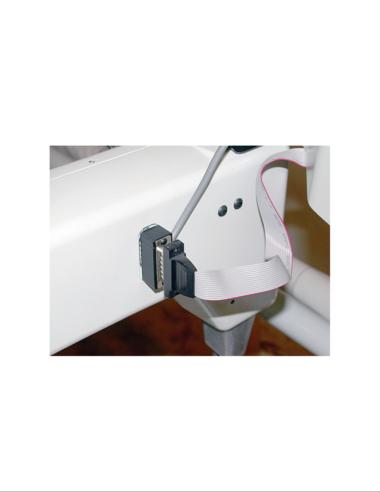
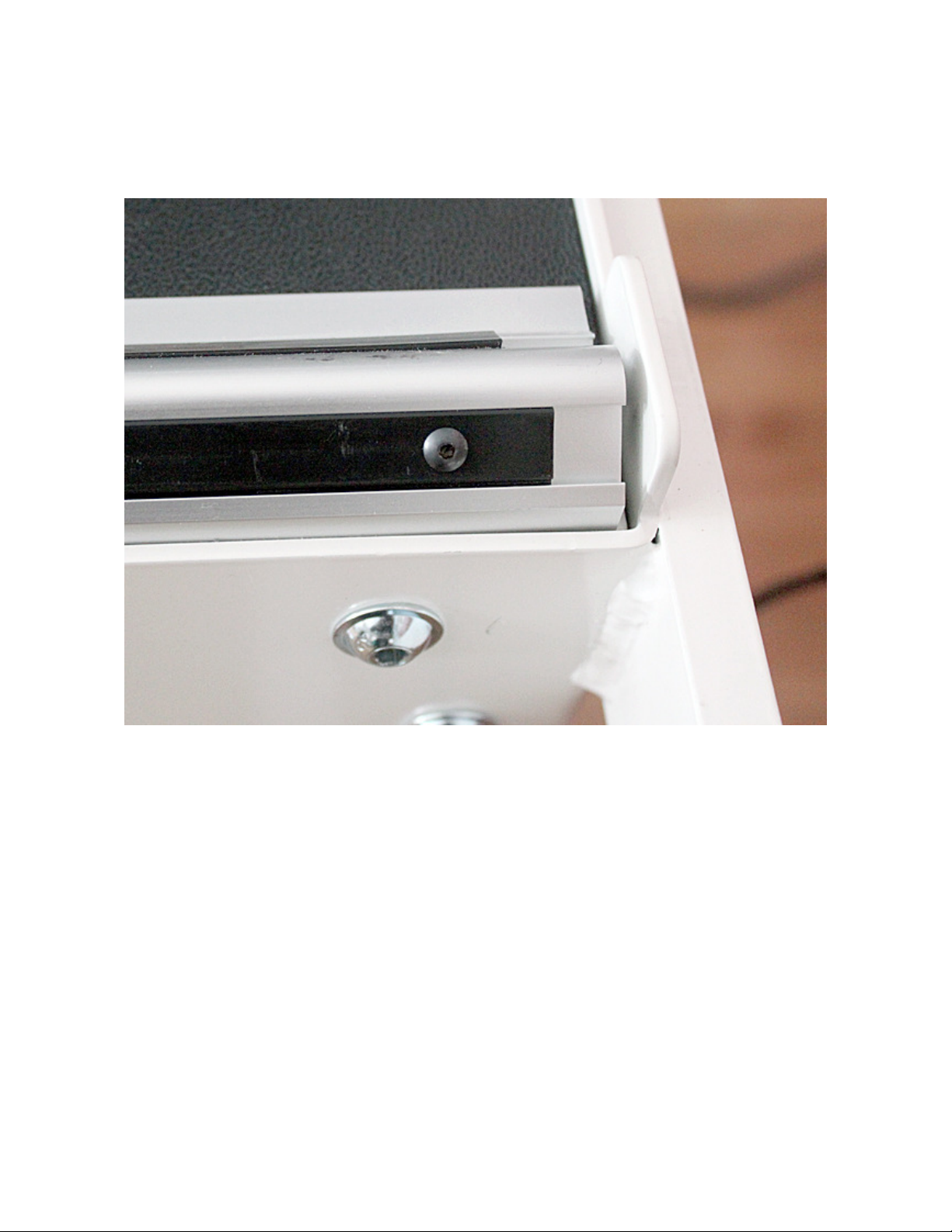
1. SWITCH CABLE
Unplug the flat cable from the connector on the side of the head.
Plug in the IQ switch cable’s in-line adapter.
Reinsert the flat cable.
Fig. 1
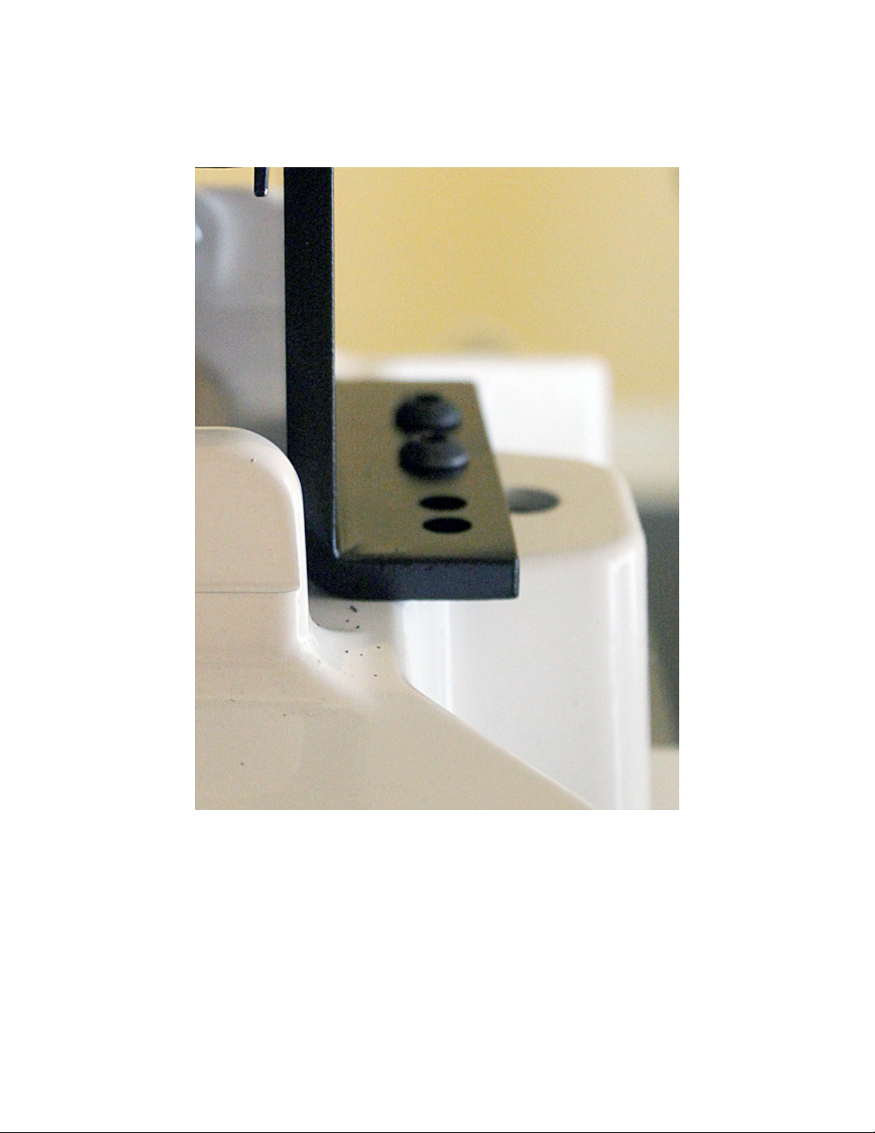
Remove the front control box from the handle assembly, and place it on the top of
the handle, so the cable does not get stretched.
Mount the extender brackets as Fig. 2 shows.
Mount the control box on the bottom of the extender brackets.

2
Fig. 2
Remove the two front screws from the handle.
Mount the computer support plate on the top of the handle, using 2 pcs M6 X 60 mm
bolts and serrated spring washers.
3
Remove the yellow thumbscrews, flip up the computer cradle and mount the
computer bracket on the support plate using 4 pcs #10-32x1/4" button-head screws.
Fig. 3
Put back the yellow thumbscrews.
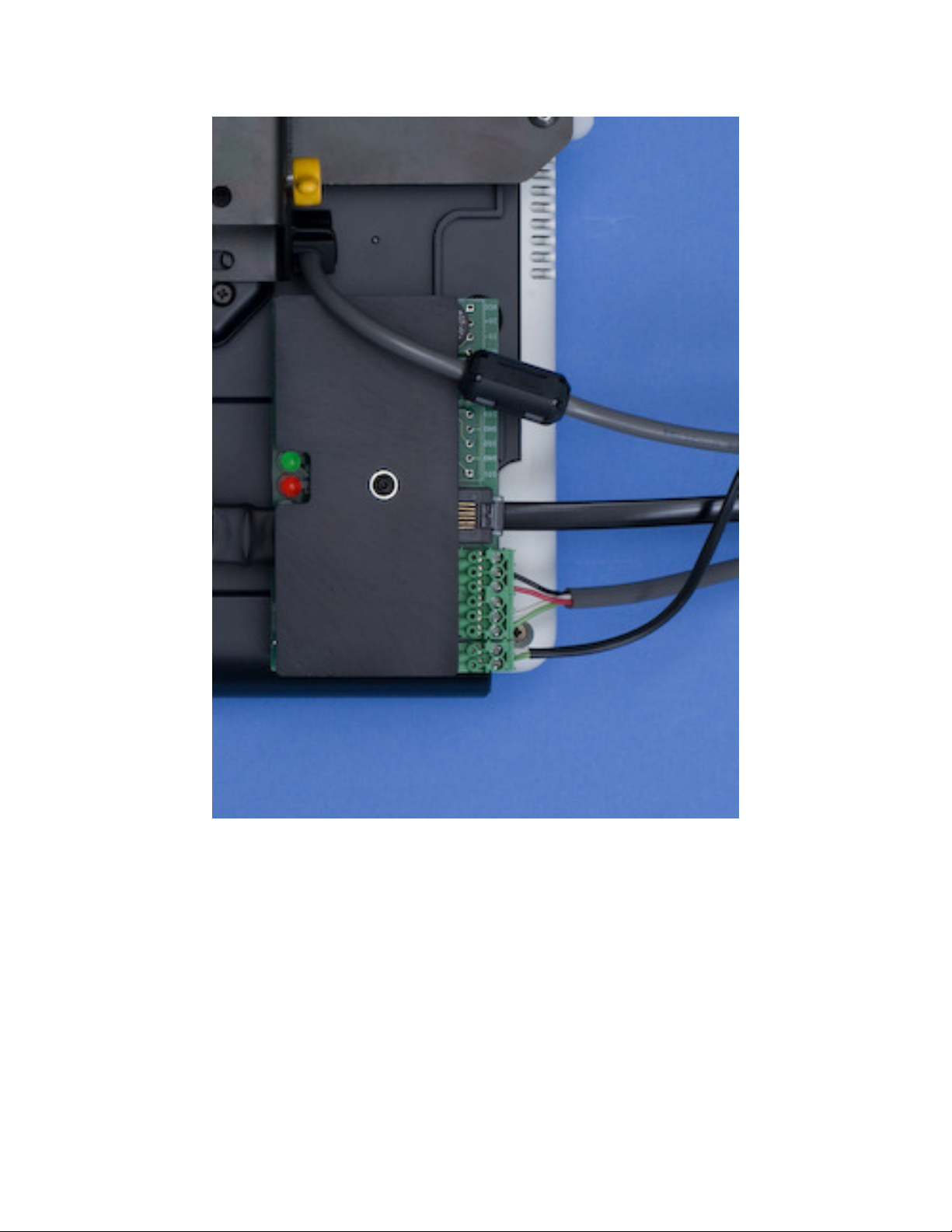
4
Fig. 4
Plug in the switch cable in the six-pin connector, as shown on Fig. 4.
Dock the computer and adjust the height and angle of the computer docking station.
Tighten the four screws at that position.

5
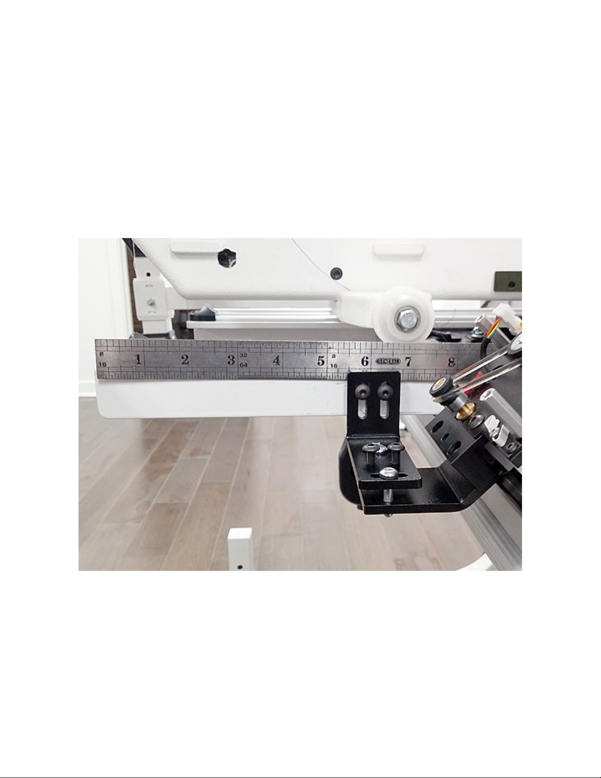
3. THREAD BREAK DETECTOR
Position the thread break detector on the top of the arm, so the hole in the bracket
is about 7" (178mm) from the rear edge of the head and the whole adhesive pad is
beyond the separation line (see Fig. 5). Mark the position of the edge of the bracket.
Fig. 5
Clean the surface where the bracket will be placed with alcohol.
Remove the clear protective foil from the double-sided tape on the bracket and push
it firmly to the surface, making sure that it sticks only to the left side of the body
(viewed from the front). Set the wheel position so it is aligned with the thread path.
Note the proper threading direction: it should be wrapped around the wheel
clockwise.

6
4. Y-MOTOR
Mount the Y-motor on the front left wheel support as Fig. 6 shows. Set the drive and
sensor wheels in the middle of the outer surface of the plastic rail and tighten the
two bolts, but do not overtighten them.
Fig. 6
Set the motor assembly's position utilizing the slots on the brackets, so both the
drive roller and sensor wheel run in the middle of the track. There should be a 1/16"
gap (about one credit card thickness) between the drive roller and the track when all
the screws are fully tightened. Move the drive roller and sensor wheel in/out to
achieve the best alignment. .For detailed installation, alignment and adjustment
instructions see the "SM-V3 Installation” and the “Motor Alignment
Procedure" documents.

7
NOTE: On the SuperMotor-V3 make sure that the motor bracket is leveled. The
top of the head of the sensor bracket limiting screw should be at least 1/8” (3
mm) to 2/10” (5 mm) elevated above the aluminum block to provide proper
movement range for the sensor.
Fig. 7
8
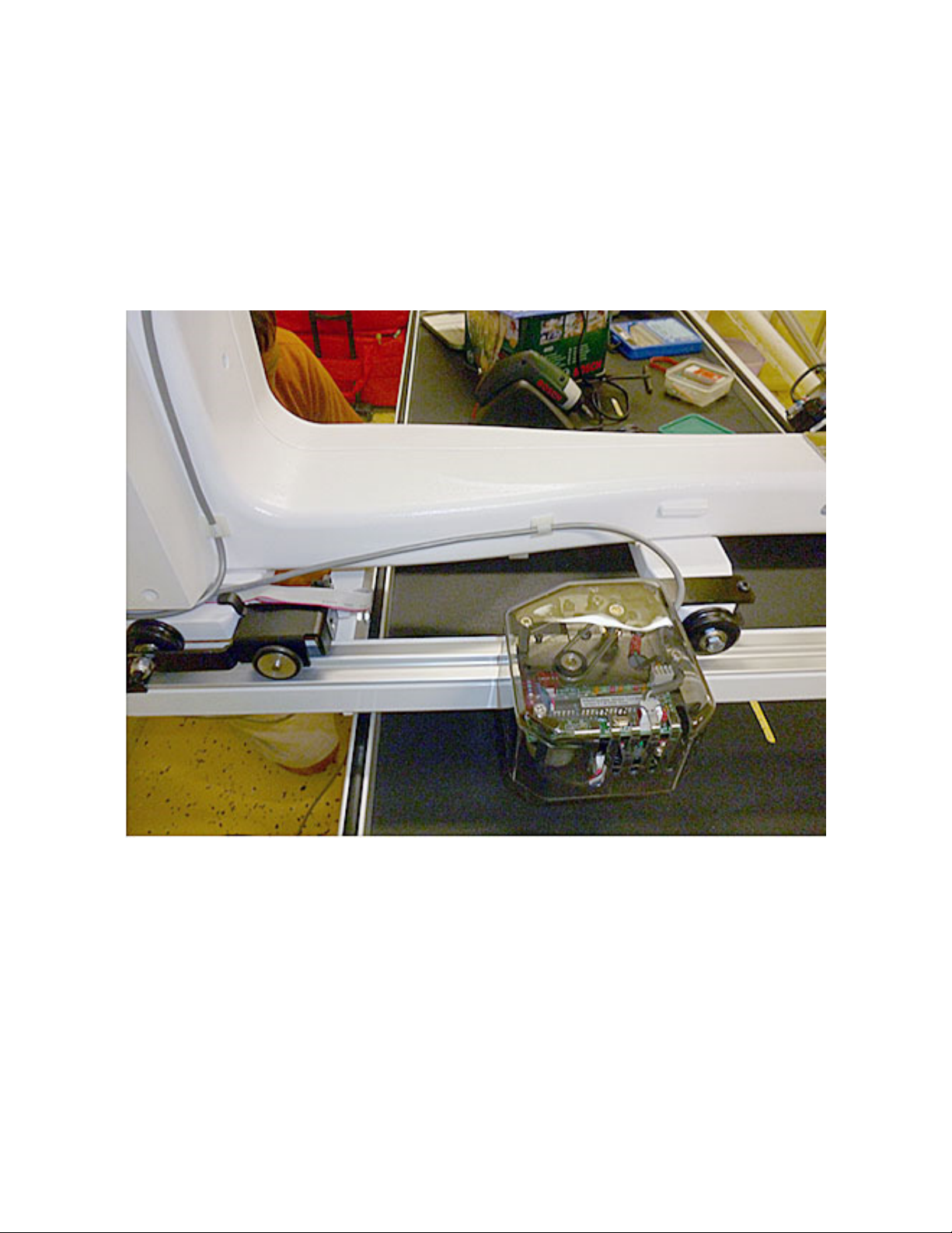
5. X-MOTOR
Remove the cover from the X-motor and put it on the bracket. Place the white
spacer hook under the limiting screw as Fig. 8 shows.
On the front of the right carriage rail, at about 5-1/2” from the front edge, push up
the aluminum mounting block so the bottom of the slot is pressed against the bottom
of the rail. Position the block so the drive wheel touches the front surface of the
slanted table rail. Tighten the large bolt firmly, so its tip cuts into the material of the
rail.
Fig. 8

9
Fig. 9
Adjust the X-motor’s position using the four-screw cluster on the bracket, so both
the drive roller and the sensor wheel run securely on the plastic insert, as shown on
Fig. 9. There should be a 1/16" gap (about one credit card thickness) between the
drive roller and the track when all the screws are fully tightened. Move the drive
roller and sensor wheel in/out to achieve the best alignment. For detailed
installation, alignment and adjustment instructions see the "SM-V3
Installation” and the “Motor Alignment Procedure" documents.
10
In order to stop the plastic insert from moving inside the aluminum track, bolt down
both ends with the included #6-32 X ¼” screws. Drill and tap holes at ¾” from each
edge of the insert and secure it with the screws.
Fig. 10

11
Move the machine all the way to the right (viewed from the back). Stop where the Y-
motor is at a safe distance from the bars on the side of the table. Clean the top of
the rail next to the carriage wheel on the right thoroughly with alcohol. Remove the
protective foil and mount one of the rubber strips on the top of the rail.
Move the machine all the way to the left (viewed from the back). Stop where the X-
motor’s sensor wheel still stays on the track. Clean the top of the rail next to the
carriage wheel on the left. Remove the protective foil and mount the other rubber
strip on the top of the rail.
Fig. 11
12
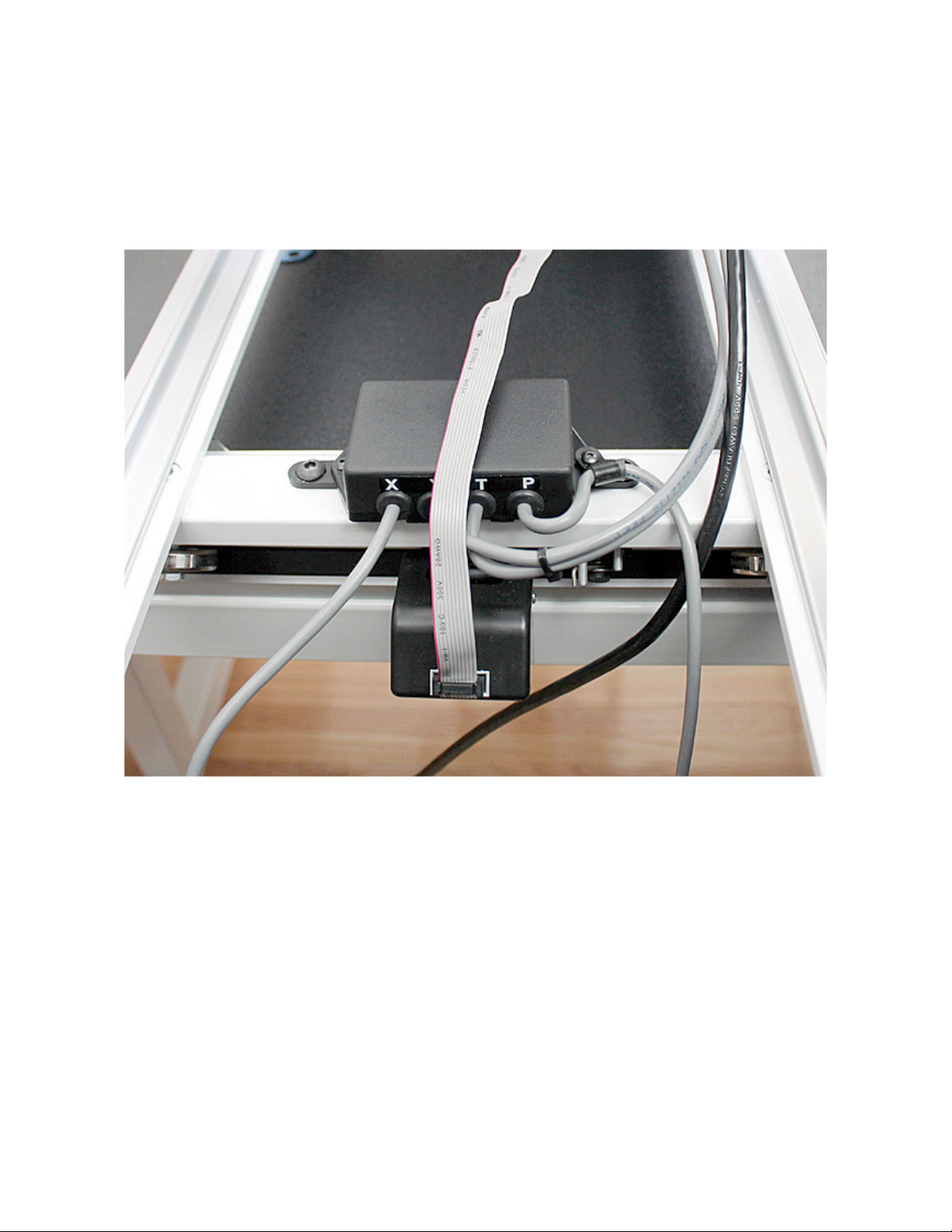
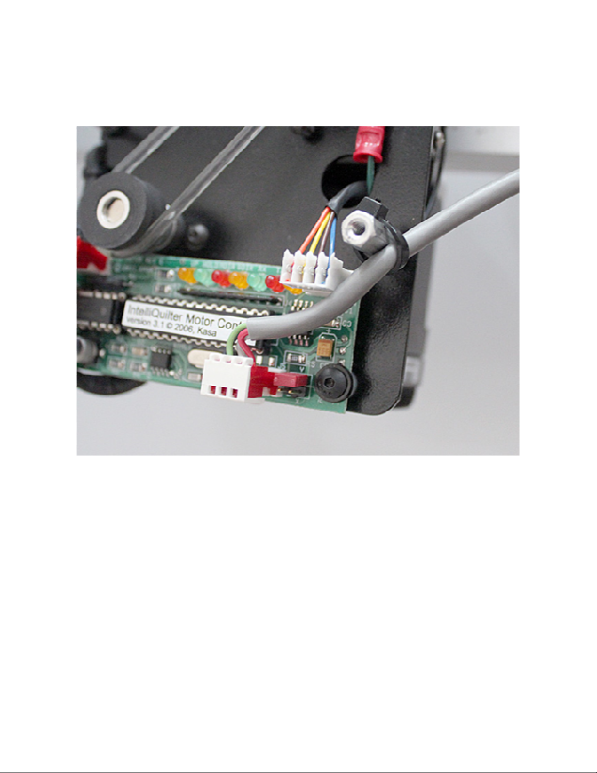
6. JUNCTION BOX
Mount the junction box in the existing holes on the rear crossbar of the carriage,
using two ¼”-20 X ½” screws, as shown on Fig. 12. Arrange the wires and the stitch
regulator cable as shown.
Fig. 12
13
7. INSTALLATION OF CABLES
Plug in the X-motor cable and secure it on the side of the carriage rail with a cable
clamp.
Run the Y-motor cable at the right side of the machine (viewed from the back),
under the control box, along the side of the lower arm. Hold the cable with one
adhesive cable clamp as Fig. 13. shows
Fig. 13
14
Clean their locations with alcohol and place adhesive cable clamps under the upper
arm as Fig. 14 shows. Insert the computer cable in the clamps.
Fig. 14
15
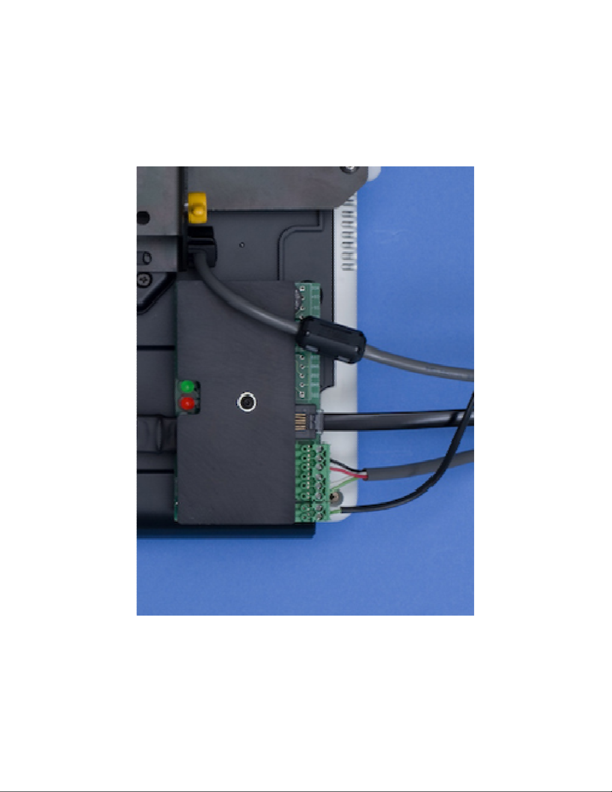
Connect the computer power and communication connectors to the docking station
as Fig.15 shows.
Plug in the thread break detector cable.
Fig. 15

16
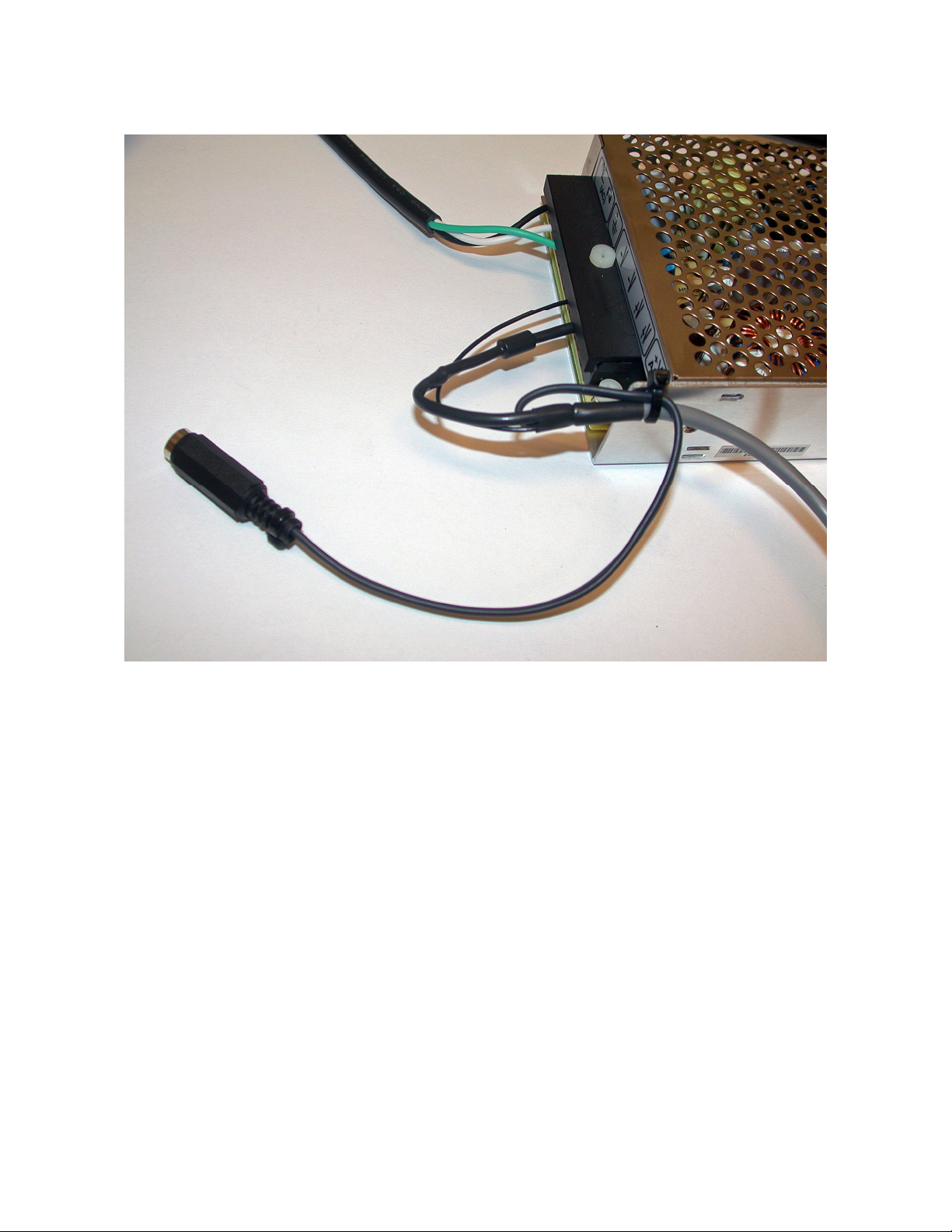
Remove the protective cover from the power supply connector.
Connect the power cable to the power supply: BLACK wire to the negative terminal,
the wire with the in-line diode to the positive terminal.
Fig. 16
Put back the protective cover.
For strain relief, tie the cable to the hole on the side of the power supply with wire
tie. Plug in the AC adapter jack.
17
Fig.17

18
Mount the power supply on one of the middle legs of the table using 14" wire ties,
as Fig. 18 shows.
Fig. 18
19
Tie the cables to the posts on both motors as Fig. 19 shows.
Fig. 19

20
Put the plastic covers on the motors. Pull up the cable in the slot at the side of the
cover as Fig. 20 shows.
Fig. 20
Table of contents
Other IntelliQuilter Sewing Machine Accessories manuals


