– 6 –
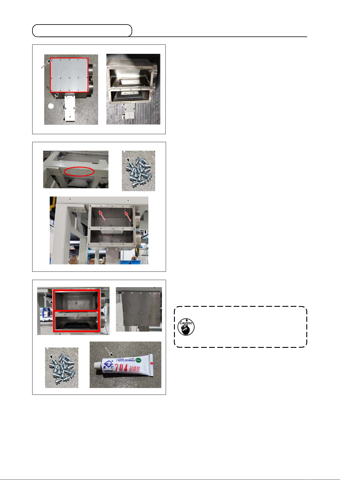
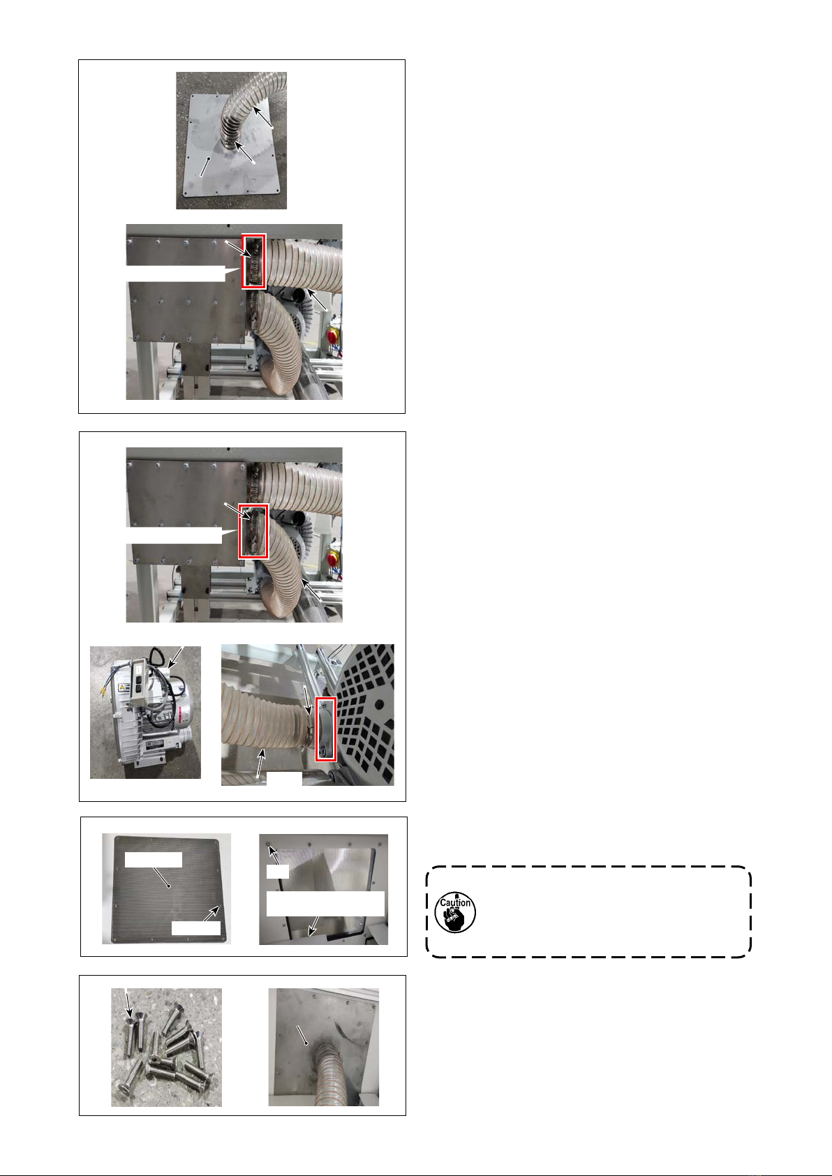
4) Put one end of pipe (1.1 m) over the cylindri-
cal part of suction cover and the other end
over the upper cylindrical part of lter box ❽until
they will go further and secure both ends of the
pipe with pipe bands .
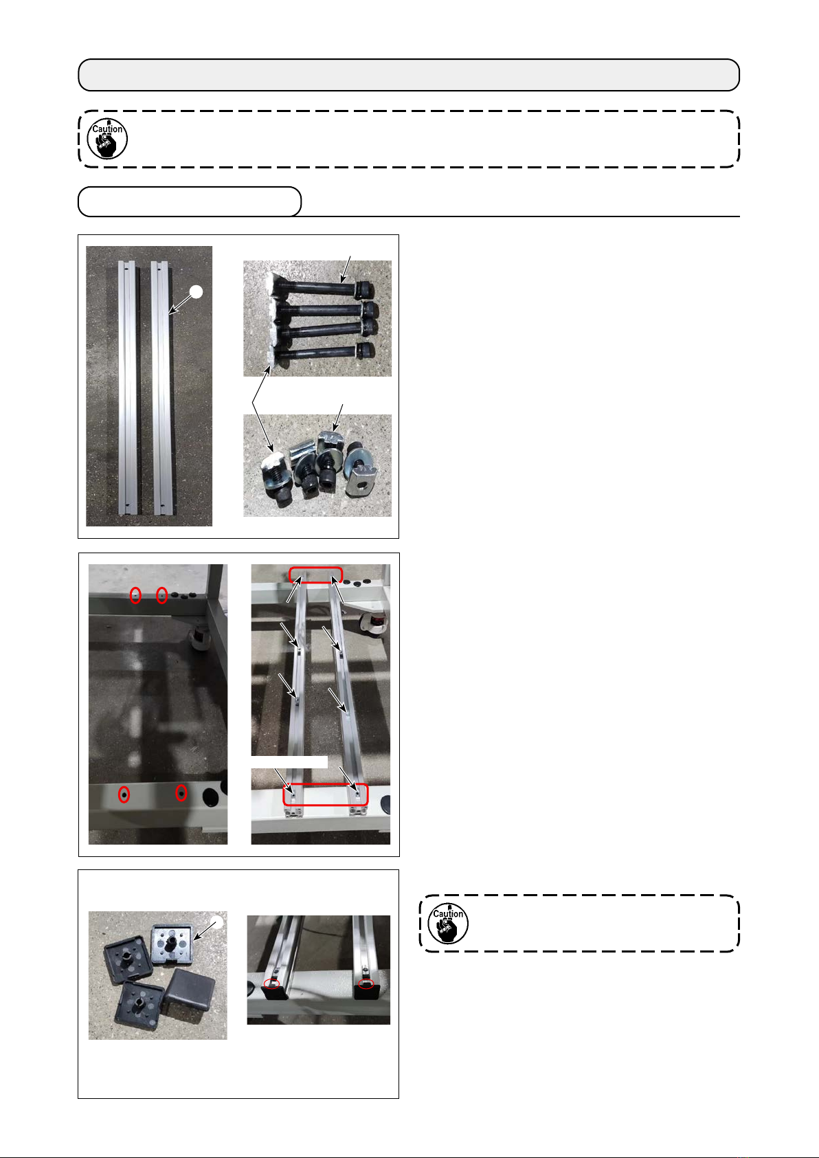
Nut
Front cover of the table
stand
Setscrew
Mesh plate
(1.1m)(1.1m)
Upper cylindrical part
❸❸
5) Put one end of pipe (0.9 m) over the cylin-
drical part of blower ❸and the other end over
lower cylindrical part of lter box ❽until they will
go no further and secure both ends of the pipe
with pipe bands .
6) Remove the table stand cover. Loose the set-
screws of the mesh plate.
There are nuts on the reverse side of
the table. Take care not to allow the
nuts to come o when you loosen the
screws.
7) Replace the setscrews of the mesh plate with
screws . Secure suction cover with screws
and the nuts.
(0.9m)(0.9m)
Lower cylindrical part