IntelliSAW 400.00152.0001 Use and care manual

Interrogator RF Board (400.00152.xxxx)
MODULE INTEGRATION MANUAL
Version:
1.1
Date:
2015, June 03
Page 1 of 18

Module Integration Manual Page 2 of 18
Interrogator RF Board (400.00152.xxxx)
TABLE OF CONTENTS
1 Overview............................................................................................................................. 3
2 Basic Specifications............................................................................................................ 4
2.1 Absolute Maximum Values........................................................................................... 4
2.2 Host Interface .............................................................................................................. 4
3 Introduction......................................................................................................................... 6
4 Communication Processor.................................................................................................. 8
4.1 COM0 (SCADA)........................................................................................................... 8
4.2 COM1 (Diagnostics)..................................................................................................... 8
4.3 I2C (Slave Sensor)....................................................................................................... 8
4.4 Command Processing.................................................................................................. 8
4.4.1 Immediate commands:.......................................................................................... 9
4.4.2 DSP High Level Commands: ................................................................................ 9
4.4.3 DSP Low Level Commands:................................................................................. 9
4.4.4 Automated Measurements.................................................................................... 9
4.5 Parsing DSP responses............................................................................................... 9
5 Power Management...........................................................................................................10
6 Host Interface ....................................................................................................................11
7 Regional Settings...............................................................................................................12
8 Approved Antennas ...........................................................................................................13
9 Regulatory Compliance......................................................................................................14
9.1 European Standard for Electromagnetic Compatibility (EN300220) ............................14
9.2 Module integration Instructions (FCC/IC)....................................................................14
9.2.1 Simultaneous Transmission Evaluation................................................................15
9.2.2 Module Antenna Installation Environments..........................................................15
9.2.3 Host User Manual Requirements.........................................................................15

Module Integration Manual Page 3 of 18
Interrogator RF Board (400.00152.xxxx)
1OVERVIEW
This document outlines the integration requirements for the IntelliSAW INTERROGATOR RF
BOARDS used for passive, remote temperature sensing with a population addition for a partial
discharge receiver.
400.00152.0001 (ASSEMBLY, INTERROGATOR RF BOARD, PARTIAL DISCHARGE,
SMA)
400.00152.0002 (ASSEMBLY, INTERROGATOR RF BOARD, SMA)
The IntelliSAW RF card is a circuit board assembly integral to multiple current and future
products and is not sold or provided to third parties, except for integration into OEM equipment
designed in cooperation with, and manufactured on behalf of IntelliSAW, so as to account for all
constraints of the module.

Module Integration Manual Page 4 of 18
Interrogator RF Board (400.00152.xxxx)
2BASIC SPECIFICATIONS
2.1 ABSOLUTE MAXIMUM VALUES
The system components have been selected and combined to allow continuous operation to an
enclosure temperature of 85⁰C. Initial prototypes are limited to +75⁰C. This allows for a +15⁰C
enclosure temperature rise. Temperature derating is expected above 2000 meters altitude;
however this has not been evaluated. Condensing humidity can alter the RF circuit properties
and, in extreme cases, result in short circuits within the circuit.
Parameter
Min
Nom
Max
Notes
Temperature
-30⁰C
+85⁰C
Enclosure temperature, to allow +70⁰C
ambient
Pressure
1 atm
Integrator must determine derating with
elevation
Humidity
95%
Non-condensing
Voltage, any
pin
-0.4V
+6V
RF input
0dBm
measurement mode
Table 1 Operation of the device beyond these limits could result in permanent damage
2.2 HOST INTERFACE
The INTERROGATOR RF BOARD requires 2.5W (nominal) from a single 5V supply. Operation
above 5.25VDC power can lead to excess power dissipation and will result in a reduction of the
maximum ambient temperature. Control signals should typically not exceed 0 –3.3V. Internal
power supplies are all internally regulated to 3.3V, and 1.8V.
All digital IO is buffered by series resistors, common mode chokes, line drivers, and Schmidt
Trigger receivers, as appropriate. When operated in a 5V logic system host, level translators
should be employed. The series resistive buffers and internal pull-up resistors result in
unreliable input logic low levels from some 5V CMOS logic hosts.
Parameter
Min
Nom
Max
Notes
5V0 Voltage
3.75V
5.0V
5.25V
Supplies 3.3V power to module via regulator
5V0 Current
0.35A
3V3 Voltage
2.25V
3.3V
5.25V
Supplies 1.8V power to DSP core via
regulator
3V3 Current
0.15A
COM0 Baud
4800
9600
115200
EEPROM settings
COM0 duplex
Half
Can be set for Full duplex
COM0
Address
1
1
247
COM0 other
8N1
Data: 8; Parity: N, E, O; Stop 1, 2
COM1 Baud
115200
Full duplex, 8 bits, no parity, 1 stop bit, addr.
1
VIH
2.6V
3.3V
except I2CDAT

Module Integration Manual Page 5 of 18
Interrogator RF Board (400.00152.xxxx)
VIL
0V
0.6V
except I2CDAT
VOH
2.5V
3.3V
0.1mA load; except I2CDAT
VOL
0V
0.8V
0.1mA load; except I2CDAT
VOH
1.8V
3.V
0.1mA load , I2CDAT
VOL
0V
1V
0.1mA load , I2CDAT
Table 2 Operation of the device within these limits has been evaluated to be reliable.

Module Integration Manual Page 6 of 18
Interrogator RF Board (400.00152.xxxx)
3INTRODUCTION
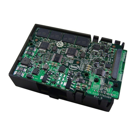
The INTERROGATOR RF BOARD is a complete interrogation module for passive SAW
sensors. It incorporates four switch-selectable sensor radio signal ports, an interrogation ASIC,
a digital signal processor, and a communications/protocol interface. The module has two serial
data ports (diagnostic port and SCADA port) and an “I2C”[
1
]port for attaching wired humidity
sensors.
The INTERROGATOR RF BOARD communications/protocol interface firmware provides high
level measurement commands and also supports MODBUS protocol. This communications and
interface module does not control critical timing related to compliance. Firmware documentation
is available on the relevant commands. A C# DLL is also available for creating PC based
applications.
Figure 1 shows one side of the INTERROGATOR RF BOARD without shielding. The blue outline encloses the
optional Class A partial discharge (PD) receiver. The red outline encloses the Class B RF transceiver circuitry. The
remainder of the circuitry incorporates an integrated Class B digital device. Connectors at lower left and lower center
are programming headers not used in normal operation and optionally unpopulated. The large header at the right is
the host interface.
1
The port is electrically I2C but uses a modified protocol of the specific sensor.
SMA1
SMA4
CASE
Earth
stud
SMA3
SMA2

Module Integration Manual Page 7 of 18
Interrogator RF Board (400.00152.xxxx)
Figure 2 shows the side of the INTERROGATOR RF BOARD facing away from the host, without shielding. The blue
outline encloses the optional Class A partial discharge (PD) receiver. The red outline encloses the Class B RF
transceiver circuitry. The remainder of the circuitry incorporates an integrated Class B digital device.
When installed in a suitable host, the resulting system will pass FCC (15.231(e)), CCC, and CE
(EN 300-220) radio parameter testing, subject to Regional Settings limits on amplitude,
frequencies, and duty cycle. Caution should be exercised in the host layout such that there are
not large amplitude noise signals immediately adjacent to the areas indicated as RF or PD. The
limited modular approval applies only to hosts designed solely or jointly by IntelliSAW and the
module is not approved for sale to other entities for insertion into systems over which IntelliSAW
does not have control to the extent to which FCC regulations apply to such products.
When operated inside a suitable-sealed metal cabinet, e.g. a switchgear or enclosed
transformer, the equipment is able to obtain the required shielding to meet the required
emissions levels while operating at full hardware power (16mW conducted with +3.5dBi antenna
gain).. End of life equipment with ungasketed doors have been demonstrated to meet FCC Part
15.231(e). KDB 550099 describes the allowed classes of equipment that are able to house the
equipment and the conditions for such installations.
RST
I2C
COM1
COM0
3V3
5V0

Module Integration Manual Page 8 of 18
Interrogator RF Board (400.00152.xxxx)
4COMMUNICATION PROCESSOR
All host activities are routed through the communications processor. This processor supports
COM0, COM1, and I2C external communications and manages internal communications with
the DSP.
4.1 COM0 (SCADA)
By default, COM0 is a half-duplex serial port intended to drive an isolated RS485 transceiver.
The signals are 3.3V CMOS levels. TE0 is controlled by the communication processor to
enable transmissions on an RS485 bus. When operated in half-duplex the module assumes it
will see a replica of TX0 bits on RX0, so the receive enable line of the RS485 adapter should
always be on.
If COM0 will be used for CMOS level communications with another
processor on the host, e.g. embedded into a meter, then the EEPROM
settings should be altered to make COM0 be full duplex or the host should
echo all characters back to the INTERROGATOR RF BOARD.
COM0 supports baud rates of 4800, 9600, 19200, 38400, 57600, and 115200. The port
supports one or two stop bits and supports odd, even, or no parity.
COM0 can support the IS485 proprietary command language (NATIVE) or MODBUS-RTU.
COM0 only responds to transmissions with a matching address, which can be between 1 and
247.
4.2 COM1 (DIAGNOSTICS)
COM0 is restricted to full duplex, 115200 baud, no parity, one stop bit, and NATIVE commands
with an address of 1. This port should be connected to an FTDI 282R USB to serial chip so that
IntelliSAW applications may directly access the INTERROGATOR RF BOARD core. This will
facilitate setup and diagnostics. To be compatible with future upgrades, the FTDI 282R chip
should also route CUSB2 to the SPARE pin of the connector, although the function of this pin
has not been selected.
4.3 I2C (SLAVE SENSOR)
The I2C port supports Sensirion® SHT-11 humidity sensors. The host system should provide
sufficient ESD and EST protection for a wired sensor if humidity and ambient temperature
measurements are desired. This sensor is automatically measured as a background task and
the results are presented in MODBUS registers. The maximum baud rate is 300.
4.4 COMMAND PROCESSING
The communications processor has multiple levels of privilege determined by passwords.
OEMs will be provided with the passwords suitable to the commands they need to access and
the documentation for those commands. Commands fall into one of four categories:

Module Integration Manual Page 9 of 18
Interrogator RF Board (400.00152.xxxx)
4.4.1 Immediate commands:
These commands include register fetches, EEPROM reads and writes, and other similar
commands that execute within the communications processor. These are executed as they are
retrieved from the input queue and their results are posted to the output queue for transmission.
4.4.2 DSP High Level Commands:
These commands are translated into one or more DSP commands. The DSP commands are
issued and, once all results are received, a high level response is posted to the output queue.
Temperature measurement, calibration, sensor definition assignment, and setting regional limits
are examples of such commands. All functions requiring transmission are subject to being
blocked by the Part 15 timing loops.
4.4.3 DSP Low Level Commands:
These commands are passed to the DSP as the DSP becomes available. The communications
chip does not wait for completion and immediately begins processing the next command. When
the DSP responds, the response is forwarded to the output queue. All functions requiring
transmission are subject to being blocked by the Part 15 timing loops except test mode
commands, such as pulse train and CW TX on.
4.4.4 Automated Measurements
In addition to processing commands from COM0 and COM1 input queues, the communications
chip also runs an internal command thread. This thread optionally sends a heartbeat command
to the DSP once every 2.5 seconds and optionally forces a reset of the DSP if there have been
no responses in the last 10 seconds. This thread measures the Sensirion® humidity sensor, if
one is attached, and posts the results to the MODBUS registers. Finally, if automated
temperature or partial discharge measurements are enabled, this thread scans the list of sensor
definitions for those sensors having automation enabled. Enabled sensors are then measured
as internally generated high level DSP commands. No response is sent to a COM port from
these commands.
4.5 PARSING DSP RESPONSES
Regardless of the source of a command, all responses from the DSP that contain sensor data
are parsed. The data is validated and calibrated, then inserted into the MODBUS registers. In
this way, MODBUS registers are updated by the most recent measurement request, regardless
of whether it was internally or externally generated.

Module Integration Manual Page 10 of 18
Interrogator RF Board (400.00152.xxxx)
5POWER MANAGEMENT
The power management module obtains two power inputs. These can be supplied from a
single 5V supply; however both pins must be powered. Pin 5V0 drives several 3.3V low dropout
regulators for the various subsystems and must be at least 3.75V for reliability over load swings
and temperature. The input level should not exceed 5.25V to reduce internal heat generation.
If the system will not be operated above 55⁰C then 6V (max) is acceptable. Pin3V3 drives a
1.8V low dropout regulator for the DSP core. The regulator can tolerate 5.35V in (6V under
55⁰C) and should exceed 2.25V for reliable operation.

Module Integration Manual Page 11 of 18
Interrogator RF Board (400.00152.xxxx)
6HOST INTERFACE
Every line entering from the host is clamped by a 6V TVS diode to CON_GND. Power lines
then pass through a PTC fuse, a Schottkey diode, and a common mode choke before passing
to the power management unit.
Signal lines (except I2CDAT and RST_SW) pass through common mode chokes, 2.2KΩ series
resistors, and a Schmidt trigger receiver or driver. RST_SW passes through a common mode
choke and an additional ferrite. This pan can either connect a physical reset switch to ground or
an open drain signal from the host. I2CDAT passes through a common mode choke, a 330Ω
series resistor, and a 10KΩ pull-up resistor before connecting to the open drain pin of the
communications processor. The host must protect this off-chip signal if it is to connect to a
wired humidity sensor.

Module Integration Manual Page 12 of 18
Interrogator RF Board (400.00152.xxxx)
7REGIONAL SETTINGS
The following are factory settings required for delivery of products in different regions. The
settings require two levels of password access (factory and distributor). Only distributors that
have been trained for professional installation will have access to the distributor settings
to allocate the appropriate region for installation.
ABS_MIN_FREQ & ABS_MAX_FREQ
The INTERROGATOR RF BOARD supports regional settings to limit the allowed transmission
frequencies: These settings default to 425MHz and 445MHz.
In CE compliant (EN300220) modes the limits are 433,266MHz to 434,554MHz. Note that CCC
allows two bands.
MAX_PPS
The INTERROGATOR RF BOARD supports four RF Port specific settings to limit the fine power
adjust setting such that the transmit power cannot exceed a predetermined limit. For standard
products these settings are factory adjusted to limit the conducted port power to +10dBm,
although the losses in the TX filter consistently limit TX power below 10dBm without adjustment.
For FCC compliance without an approved metallic enclosure, the system has been evaluated
with a MAX_PPS value of 0 (minimum preamplifier gain).
MAX_PA
The INTERROGATOR RF BOARD supports an EEPROM setting to limit TX power downward in
2.2dB increments. With PA=7, the maximum allowed power (as set by PPS) is generated. With
PA=0 the generated power is reduced by 15.4dB. The PA value is dynamically adjusted to
attain a desired receive signal strength between 0 and the regional limit setting. For FCC
compliance without an approved metallic enclosure, the system has been evaluated with a
MAX_PA value of 3. The conducted TX power associated with PA=3 and PPS=0 on the
reference board was evaluated as -5.5dBm (282μW).
MIN_OFF_TIME, MAX_ON_TIME, and ON_OFF_RATIO
Transmission ON time limits and IDLE time requirements are controlled by three parameters. A
sophisticated algorithm maximizes ON time within a given regulatory setting. The transmitter
can be IDLE (WAITOVER state), FORCED_OFF (WAITING state), or ACTIVE (TXING state). A
state transition from IDLE to ACTIVE occurs on a first transmission. The ACTIVE_TIME is
monitored and at MAX_ON_TIME (1000ms under FCC 15.231(e)), the state transitions to
FORCED_OFF. Another timer monitors the SILENT_TIME since the last transmission ended.
If this SILENT_TIME timer exceeds MIN_OFF_TIME (10000ms in FCC 15.231(e) and 3600ms
under CE 10% duty cycle) and exceeds the product of ACTIVE_TIME * ON_OFF_RATIO (30 in
FCC 15.231(e) and 1 in CE 10% duty cycle), then the state reverts to IDLE.

Module Integration Manual Page 13 of 18
Interrogator RF Board (400.00152.xxxx)
8APPROVED ANTENNAS
The following antennas have been approved for use with the INTERROGATOR RF BOARD:
IntelliSAW Part #
Type
Gain
IA-xx-5-y
Monopole (5 cm mast)
-1 dBi
IA-xx-9-y
Monopole (9 cm mast)
+1 dBi
IA-xx-17-y
Monopole (17 cm mast)
+3.2 dBi
IA-xx-TPD
Patch inverted F (PIFA)
+3.5 dBi
Part Number (“xx”) indicates magnetic (MM) or bolt (BM) mount.
Part Number (“y”) indicates cable length and is offered in 3, 5, or 7 meters.
Safety constraints in high voltage systems require the cable shields be bonded to earth
and that the antenna signal lines be inductively earthed such that 50/60Hz signals are not
induced from the high voltage systems.

Module Integration Manual Page 14 of 18
Interrogator RF Board (400.00152.xxxx)
9REGULATORY COMPLIANCE
9.1 EUROPEAN STANDARD FOR ELECTROMAGNETIC COMPATIBILITY (EN300220)
The INTERROGATOR RF BOARD module has been tested along with the IntelliSAW IS485
power and interface host board. This reference design has been found to be compliant with
Directive 99/5/EC (R&TTE), either through operation enforced to be compliant with EN300220
or though fixed site installation compliant with EN55022. It is compliant by exemption from
DIRECTIVE 2006/95/EC. The following constraints are placed on the host system to attain
such compliance:
1. Case ground connection of INTERROGATOR RF BOARD must connect to protective
earth by a wire of at least 1mm2diameter and < 25cm in length.
2. The host power supply must meet EN55022 Class A conducted EMI back into the power
mains.
3. The host power supply must not inject switcher transients exceeding 400mVpp on any
power, ground, or signal line entering the INTERROGATOR RF BOARD.
4. The host must protect all INTERROGATOR RF BOARD digital control and power signals
from conducted RFI, electrical fast transients, and surges to the desired/required levels.
In addition to these host requirements, EN55022 requires a combination of switchgear shielding,
antenna gain, and peak transmit power such that “cabinet radiation” is below the allowed limits.
The OEM is responsible for ensuring such limits are met or that appropriate regulatory waivers
and exemptions are obtained.
In order to meet EN300220, only a single sensor band (“ISM”) is allowed. In one mode, the
transmit power is limited to 0dBm with no duty cycle limitations. In another mode, the transmit
power is limited to +10dBm with a required 10% duty cycle.
Integration partners have obtained CCC type test approval using the IS-485 product; however
the INTERROGATOR RF BOARD module has not yet been certified under CCC.
9.2 MODULE INTEGRATION INSTRUCTIONS (FCC/IC)
The INTERROGATOR RF BOARD (Model: 400.00152) has been granted modular approval for
fixed applications where IntelliSAW host products may use the module in their final products
without additional FCC / IC (Industry Canada) certification if they meet the following conditions.
Otherwise, additional FCC / IC approvals must be obtained.
The host product with the module installed must be evaluated for simultaneous
transmission requirements.
The host product must be professionally installed. If this is not the case, either non-
standard connectors must be used or the antenna must be permanently affixed.
The user manual for the host product must clearly indicate the operating requirements
and conditions that must be observed to ensure compliance with current FCC / IC RF
exposure guidelines.

Module Integration Manual Page 15 of 18
Interrogator RF Board (400.00152.xxxx)
A label must be affixed to the outside of the host product with the following statements:
oThis device contains FCCID: 2AEAE-ISAW-RF-H0215
oContains device certified under IC: 11526A-ISAWRFH0215
The final host / module combination may also need to be evaluated against the FCC Part 15B
criteria for unintentional radiators in order to be properly authorized for operation as a Part 15
digital device.
9.2.1 Simultaneous Transmission Evaluation
This module has NOT been evaluated or approved for simultaneous transmission as it is
impossible to determine the exact multi-transmission scenario that a host manufacturer may
choose. Any simultaneous transmission condition established through module integration into a
host product must be evaluated per the requirements in FCC KDB447498D01(8).
9.2.2 Module Antenna Installation Environments
The INTERROGATOR RF BOARD module with approved antennas have been tested and
approved for professional installation in the following environments:
1. Metal enclosures described in the IEEE/ANSI Std C37.20, or UL and NEMA
specifications derived from Std C37.20, as indicated in KDB 550099. The host device is
not required to be in such an enclosure since the antenna is wired away from the host.
NOTES:
IEEE C37.20 testing is related to antennas being inside the equipment and relates only
to shielding of the conducted power of the transmitter at fundamental frequencies to
provide radiated emissions below the levels allowed for FCC. Changes to the
INTERROGATOR RF BOARD module that do not change the conducted power or alter
the antenna should not require field test to be repeated.
All other FCC part 15 requirements of the INTERROGATOR RF BOARD module met
independent of C37.20 or any other enclosure. An addition to the grant conditions for
additional enclosures at the same or lower conducted power will require a justification,
may require field testing for fundamental field strength, but shall not require repeat of
spurious emissions testing if the INTERROGATOR RF BOARD module has not been
modified.
9.2.3 Host User Manual Requirements
CAUTION: Any changes or modifications not expressly approved by IntelliSAW Inc.
could void the user’s authority to operate the equipment.

Module Integration Manual Page 16 of 18
Interrogator RF Board (400.00152.xxxx)
9.2.3.1 FCC Requirements
Consistent with §2.909(a), the following text must be included within the user’s manual or
operator instruction guide for the final commercial product.
(Required OEM content data)
Operating Requirements and Conditions:
This device complies with Part 15 of the Federal Communications Commission (FCC) Rules.
Operation is subject to the following conditions:
This device may not cause harmful interference.
This device must accept any interference received, including interference that may
cause undesired operation.
FCC ID:
The user manual must contain the following:
This product contains FCCID: 2AEAE-ISAW-RF-H0215
Note: In the case where the Host / Module combination has been re-certified the FCCID shall
appear in the product manual as follows: FCCID: (Include Standalone FCC ID)
FCC Part 15 Statement (Only Include if FCC Part 15 is Required on the End Product):
Note: This equipment has been tested and found to comply with the limits for a (OEM to insert
device type: Class A or Class B) digital device, pursuant to Part 15 of the FCC Rules. (OEM
must follow Part 15 guidelines (§15.105 and §15.19) to determine additional statements
required in this section for their device class)
Installation Requirements
The INTERROGATOR RF BOARD module and approved antennas can be professionally
installed in the following installation environments:
1. Metal enclosures described in the IEEE/ANSI Std C37.20, or UL and NEMA
specifications derived from Std C37.20, as indicated in KDB 550099. The host device is
not required to be in such an enclosure since the antenna is wired away from the host.
9.2.3.2 Industry Canada Requirements
Consistent with RSP-100 (issue 10), section 3.2 the following text must be included within the
user’s manual or operator instruction guide for the final commercial product in both English and
French.
(Required OEM content data)
Operating Requirements and Conditions:

Module Integration Manual Page 17 of 18
Interrogator RF Board (400.00152.xxxx)
This device complies with Industry Canada license-exempt RSS standard(s). Operation is
subject to the following conditions:
This device may not cause harmful interference.
This device must accept any interference received, including interference that may
cause undesired operation.
Cet appareil se mets en conformité avec les normes CNR d’Industrie Canada applicables aux
appareils radio exempts de licence. L’exploitation est autorisée aux conditions suivantes:
L’appareil ne produit pas de brouillage malfaisant.
L’appareil doit accepter tout brouillage radioélectrique reçu, y compris le brouillage qui
pourrait provoquer le fonctionnement non désiré.
Industry Canada (IC) ID:
This product contains device certified under IC: 11526A-ISAWRFH0215
Note: In the case where the Host / Module combination has been re-certified the IC ID shall
appear in the product manual as follows: IC: (Include Standalone IC ID)
Ce produit contient un appareil certifié en vertu IC: 11526A - ISAWRFH0215
A remarquer: Au cas où la combinaison hôte / Module avait été certifié de nouveau,
l'identification aurait dû figurer dans le manuel du produit comme suit: IC: (Inclure autonome IC
ID).
Transmitters
Under Industry Canada regulations, this radio transmitter may only operate using an antenna of
a type and maximum (or lesser) gain approved for the transmitter by Industry Canada. To
reduce potential radio interference to other users, the antenna type and its gain should be so
chosen that the equivalent isotropically radiated power (e.i.r.p.) is not more than that necessary
for successful communication.
Conformément à la réglementation d’Industrie Canada, cet émetteur radio peut fonctionner avec
une antenne d’un type et d’un gain maximal (ou inférieur) approuvé pour l’émetteur par Industrie
Canada. Pour réduire les risques de brouillage radioélectrique aux autres utilisateurs, il faut
choisir le type d’antenne et son gain de sorte afin que la même puissance isotrope rayonnée
quivalente (p.i.r.e.) ne dépasse pas l’intensité nécessaire à l’établissement de la communication
satisfaisante.
Antennas
This radio transmitter (IC: 11526A-ISAWRFH0215) has been approved by Industry Canada to
operate with the antenna types listed below with the maximum permissible gain indicated.
Antenna types not included in this list, having a gain greater than the maximum gain indicated
for that type, are strictly prohibited for use with this device.

Module Integration Manual Page 18 of 18
Interrogator RF Board (400.00152.xxxx)
Cet émetteur radio (IC: 11526A-ISAWRFH0215) a été approuvé par l’Industrie Canada pour
fonctionner avec les types d’antenne énumérés ci-dessous. Le gain maximum permis est
précisé pour chaque type d’antenne. Les types d’antenne non inclus dans cette liste, dont le
gain soit plus grand que le gain maximum indiqué, sont strictement interdits pour l’utilisation de
l’émetteur:
IntelliSAW Part #
Type
Gain
IA-xx-5-y
Monopole (5 cm mast)
-1 dBi
IA-xx-9-y
Monopole (9 cm mast)
+1 dBi
IA-xx-17-y
Monopole (17 cm mast)
+3.2 dBi
IA-xx-TPD
Patch inverted F (PIFA)
+3.5 dBi
Part Number (“xx”) indicates magnetic (MM) or bolt (BM) mount.
Part Number (“y”) indicates cable length and is offered in 3, 5, or 7 meters.
Référence ( "xx" ) indique magnétique ( MM ) ou un boulon ( BM ) de montage.
Référence ( " y" ) indique la longueur du câble et est offerte en 3 , 5 ou 7 mètres.
Installation Requirements
The INTERROGATOR RF BOARD (IC: 11526A-ISAWRFH0215) module and approved
antennas can be professionally installed in the following installation environments:
1. Metal enclosures described in the IEEE/ANSI Std C37.20, or UL and NEMA
specifications derived from Std C37.20, as indicated in FCC KDB 550099. The host
device is not required to be in such an enclosure since the antenna is wired away from
the host.
Le module INTERROGATOR RF BOARD (IC: 11526A-ISAWRFH0215) et les antennes
approuvées peuvent être installés professionnellement dans les environnements d'installation
suivants:
1. Boîtiers métalliques décrits dans la norme IEEE / ANSI Std C37.20, ou UL et les
spécifications NEMA dérivés de Std C37.20, comme indiqué dans la FCC KDB 550099.
Le dispositif d'accueil ne doit pas être dans une telle enceinte à cause du fait que
l'antenne soit câblée loin de l'hôte.
This manual suits for next models
1
Table of contents
