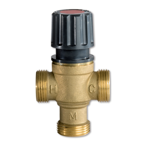
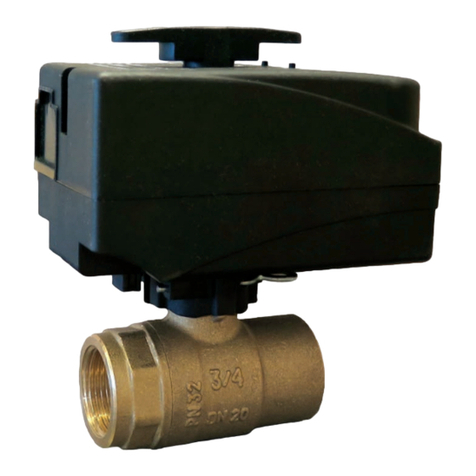
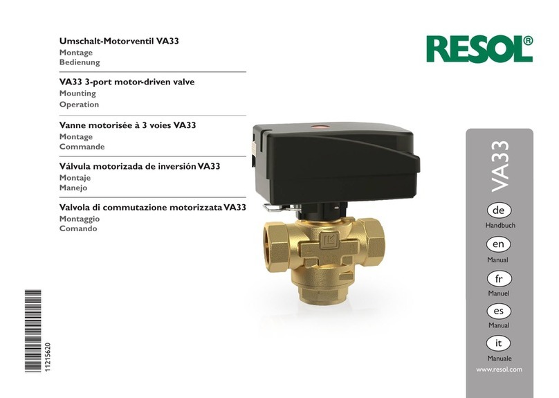
Resol VA300 User manual

*11207220*
11207220
Umschaltventil VA300
Stellantrieb SVA
Montage
Bedienung
VA300 Changeover valve
SVA Actuator
Mounting
Operation
Electrovanne d’inversionVA300
Moteur SVA
Montage
Commande
Válvula de inversiónVA300
Servomotor SVA
Montaje
Manejo
Valvola di inversioneVA300
Attuatore SVA
Montaggio
Comando
www.resol.de
de
Handbuch
VA300
Manual
en
Manuel
fr
Manual
es
Manuale
it

de
2
Angaben zum Gerät
BestimmungsgemäßeVerwendung
Das Ventil und der Stellantrieb sind für Schaltprozesse inner-
halb einer Solar- oder Heizungsanlage unter Berücksichtigung
der in dieser Anleitung angegebenen technischen Daten be-
stimmt.
Die bestimmungswidrigeVerwendung führt zum Ausschluss jeg-
licher Haftungsansprüche.
CE-Konformitätserklärung
Das Produkt entspricht den relevanten Richtlinien und
ist daher mit der CE-Kennzeichnung versehen. Die
Konformitätserklärung kann beim Hersteller angefor-
dert werden.
Entsorgung
• Verpackungsmaterial des Gerätes umweltgerecht entsorgen.
• Altgeräte müssen durch eine autorisierte Stelle umweltge-
recht entsorgt werden. Auf Wunsch nehmen wir Ihre bei
uns gekauften Altgeräte zurück und garantieren für eine
umweltgerechte Entsorgung.
Irrtum und technische Änderungen vorbehalten
© 20161019_11207220_VA300.mon5s.indd
Vielen Dank für den Kauf dieses RESOL-Gerätes.
Bitte lesen Sie diese Anleitung sorgfältig durch, um die Leis-
tungsfähigkeit dieses Gerätes optimal nutzen zu können. Bitte
bewahren Sie diese Anleitung sorgfältig auf.
Sicherheitshinweise
Bitte beachten Sie diese Sicherheitshinweise genau, um Gefah-
ren und Schäden für Menschen und Sachwerte auszuschließen.
Symbolerklärung
WARNUNG! Warnhinweise sind mit einem Warndreieck
gekennzeichnet!
ÎEs wird angegeben, wie die Gefahr ver-
mieden werden kann!
ÎTextabschnitte, die mit einem Pfeil gekennzeichnet sind, for-
dern zu einer Handlung auf.
Hinweis
Hinweise sind mit einem Informationssymbol gekenn-
zeichnet.
Vorschriften
Beachten Sie bei Arbeiten die jeweiligen, gültigen Normen,Vor-
schriften und Richtlinien!
Zielgruppe
Diese Anleitung richtet sich ausschließlich an autorisierte Fach-
kräfte. Die Installation darf nur durch geschultes Fachpersonal
ausgeführt werden.

de
3
UmschaltventilVA300
Das VA300 ist ein 3-Wege-Ventil mit elektrothermischem Stel-
lantrieb. Die ca. 3-minütige Stellzeit ermöglicht eine wasser-
schlagfreieVolumenstromregelung.
Die Anleitung beschreibt die folgenden Ausführungen:
• VA300-NC: UmschaltventilVA300 mit Stellantrieb strom-
los geschlossen SVA-NC (Durch ussrichtung von I nach III)
• VA300-NO: UmschaltventilVA300 mit Stellantrieb strom-
los offen SVA-NO (Durch ussrichtung von I nach II)
DN 20 25 32 40
L 64 84 115 115
H 36 46 106 106
H144,5 50 64 64
H293 98,5 - -
SW 37 47 66 66
VA300-NC
Durch ussrichtung
von I nach III
VA300-NO
Durch ussrichtung
von I nach II

de
4
Technische DatenVentil
Temperaturbereich: bis 120 °C, temperaturbeständig,
kurzzeitig: bis 140 °C
Material
Gehäuse: korrosionsbeständiger Rotguss
Innenteile: Messing und nichtrostender Stahl
Dichtungen: EPDM
Max. Druck: 10bar
Anschlussgewinde: ¾", 1", 1¼", 1½"
Technische Daten Stellantrieb
Versorgung: 230V~, 50 … 60Hz
Stromaufnahme (typisch): 26 mA
Leistungsaufnahme: max. 2,5 W
Einschaltstrom: < 1A
Grundzustand:
SVA-NC: stromlos geschlossen (Durchussrichtung von I nach III)
SVA-NO: stromlos offen (Durchussrichtung von I nach II)
Betriebstemperatur: -25…50 °C
Federkraft: 90 N
Hub: 4 mm
Schutzart: IP 44 (bei senkrechter Montage)
Schutzklasse: II
Stellzeit: ca. 3 min
Verschmutzungsgrad: 2
Anschlussleitung: 2 x 0,5 mm²; 100 cm

de
5
1. Installation
1.1 Montage
ÎDen Stellantrieb (nur bei Typ SVA-NC) in die Position
Handbetrieb bringen, siehe Seite 6.
ÎDen Stellantrieb mit der Überwurfmutter auf dem Ventil
befestigen.
Hinweis
Das Ventil kann waagerecht oder senkrecht eingebaut
werden, jedoch nicht mit dem Antrieb nach unten.
Die Montage des Ventils ist nach den einschlägigen Regeln der
Technik vorzunehmen. Die Montage darf nur vom Fachmann
ausgeführt werden! Die einschlägigenVDE- und TÜV-Vorschrif-
ten sind zu beachten!
1.2 Elektrischer Anschluss
DieAnschlussverdrahtung ist nach dem entsprechenden Schalt-
plan durchzuführen.
Die Leitungen des Stellantriebes an die Relaisausgänge des Reg-
lers anschließen:
Îdie braune Leitung an die Klemme des Relaisausganges an-
schließen
Îdie blaue Leitung an die Klemme mit dem Neutralleiter
anschließen
Eine Absicherung der einzelnen Geräte ist zu empfehlen. Der
Leiterquerschnitt soll bei 230 V~ Betriebsspannung den ein-
schlägigen örtlichen und VDE-Richtlinien entsprechen.
Beim Betrieb mehrerer Ventile mit Stellantrieb in einer Anlage
unbedingt auf Phasengleichheit achten!
Hinweis
Bei Verlegung der Anschlussleitung darauf achten, dass
diese nicht in Wärmekontakt mit heißen Anlagenteilen
(z.B. Radiator, Rohrleitungen etc.) steht.
Nach Anschluss der Leitung an den Regler oder Thermostaten
ist der Stellantrieb einsatzfähig.
Beispiel: NR1
Stellantrieb
braun blau

de
6
3. Hubanzeige
Die Hubanzeige hinter der transparenten Abdeckung an der
Frontseite des Stellantriebes zeigt an, wie weit der Stellantrieb
geöffnet ist. Sie dient damit der Funktionsüberwachung des
Stellantriebes.
SVA-NC:
Läuft die Anzeige nach ca. 3min anliegender Betriebsspannung
auf die Position „offen“,so arbeitet das Gerät einwandfrei.Trennt
man den Stellantrieb von der Spannung, muss die Hubanzeige
innerhalb von ca. 3 min die Position „geschlossen“ anzeigen.
Der Stellantrieb SVA-NO arbeitet entsprechend umgekehrt.
Position „geschlossen“
Die Hubanzeige ist nur am unteren Rand sichtbar: Der Stellan-
trieb hält dasVentil geschlossen.
Position „offen“
Die Hubanzeige füllt fast die gesamte transparente Abdeckung
aus: Der Stellantrieb hält dasVentil geöffnet.
2. Bedienung
Der Stellantrieb verfügt über einen Handschalter, der mit ei-
nem Schraubendreher betätigt werden kann. Mit diesem Hand-
schalter können 2 Betriebszustände eingestellt werden:
• Handbetrieb
• Automatikbetrieb
WARNUNG! Elektrischer Schlag!
Vor der Umstellung den Stellantrieb von der
Spannungsversorgung trennen!
Handbetrieb:
Der Stellantrieb öffnet das Ventil unabhängig von
der anliegenden Spannung. Diese Position erleich-
tert die Montage und ermöglicht einen Betrieb
der Anlage bei Ausfall des Reglers.
Automatikbetrieb:
Der Stellantrieb steuert das Ventil entsprechend
der anliegenden Spannung. Diese Position ist für
den normalen Betrieb erforderlich.

de
7
4. Anwendungsbeispiele
1 Kollektor, 1 Speicher, Schichtbeladung 1 Kollektor, 2 Speicher, wahlweise Beladung mit Nachheizung

Wichtiger Hinweis
Die Texte und Zeichnungen dieser Anleitung entstanden mit
größtmöglicher Sorgfalt und nach bestem Wissen. Da Fehler
nie auszuschließen sind, möchten wir auf folgendes hinweisen:
Grundlage Ihrer Projekte sollten ausschließlich eigene Berech-
nungen und Planungen an Hand der jeweiligen gültigen Normen
und Vorschriften sein. Wir schließen jegliche Gewähr für die
Vollständigkeit aller in dieser Anleitung veröffentlichten Zeich-
nungen und Texte aus, sie haben lediglich Beispielcharakter.
Werden darin vermittelte Inhalte benutzt oder angewendet, so
geschieht dies ausdrücklich auf das eigene Risiko des jeweiligen
Anwenders. Eine Haftung des Herausgebers für unsachgemäße,
unvollständige oder falsche Angaben und alle daraus eventuell
entstehenden Schäden wird grundsätzlich ausgeschlossen.
Anmerkungen
Das Design und die Spezikationen können ohne Vorankündi-
gung geändert werden.
Die Abbildungen können sich geringfügig vom Produktionsmo-
dell unterscheiden.
Impressum
Diese Montage- und Bedienungsanleitung einschließlich aller
seinerTeile ist urheberrechtlich geschützt.EineVerwendung au-
ßerhalb des Urheberrechts bedarf der Zustimmung der Firma
RESOL–Elektronische Regelungen GmbH. Dies gilt insbeson-
dere für Vervielfältigungen/Kopien, Übersetzungen, Mikrover-
lmungen und die Einspeicherung in elektronischen Systemen.
© RESOL–Elektronische Regelungen GmbH
RESOL– Elektronische Regelungen GmbH
Heiskampstraße 10
45527 Hattingen/Germany
Tel.: +49 (0) 23 24 / 96 48 - 0
Fax: +49 (0) 23 24 / 96 48 - 755
Internet: www.resol.de
E-Mail: [email protected]
Ihr Fachhändler

VA300 Changeover valve
SVA Actuator
Mounting
Operation
Manuel
VA300
en

en
10
Information about the product
Proper usage
The valve and the actuator are designed for switching pro-
cesses in a solar or heating systems in compliance with the
technical data specied in this manual.
Improper use excludes all liability claims.
CE-Declaration of conformity
The product complies with the relevant directives and
is therefore labelled with the CE mark. The Declara-
tion of Conformity is available upon request, please
contact the manufacturer.
Disposal
• Dispose of the packaging in an environmentally sound
manner.
• Dispose of old appliances in an environmentally sound
manner. Upon request we will take back your old appliances
bought from us and guarantee an environmentally sound
disposal of the devices.
Subject to technical change. Errors excepted.
Thank you for buying this product.
Please read this manual carefully to get the best performance
from this unit. Please keep this manual carefully.
Safety advice
Please pay attention to the following safety advice in order to
avoid danger and damage to people and property.
Description of symbols
WARNING! Warnings are indicated with a warning
triangle!
ÎThey contain information on how to
avoid the danger described.
ÎArrows indicate instruction steps that should be carried
out.
Note
Notes are indicated with an information symbol.
Instructions
Attention must be paid to the valid local standards, regulations
and directives!
Target group
These instructions are exclusively addressed to authorised
skilled personnel.
Installation must be effected by trained professionals only.

en
11
VA300 Changeover valve
The VA300 is a 3-port-valve with an electrothermal actuator.
The actuating time of approx. 3 minutes enables a ow rate
regulation without water hammers.
The following versions are described in this manual:
• VA300-NC: VA300 3-port valve with actuator normally
closed SVA-NC ( ow direction from I to III)
• VA300-NO: VA300 3-port valve with actuator normally
open SVA-NO ( ow direction from I to II)
DN 20 25 32 40
L 64 84 115 115
H 36 46 106 106
H144,5 50 64 64
H293 98,5 - -
SW 37 47 66 66
VA300-NC
ow direction from I to III
VA300-NO
ow direction from I to II

en
12
mass flow rate m [kg/h]
.
pressure loss Δp [kPa]
pressure loss Δp [mbar]
pressure loss Δp [mm head]
Technical data valve
Max. operating temperature: Long-term: 120 °C
Short-term: 140 °C
Material
Vlave body: corrosion-resistant red bronze
Internal parts: brass and corrosion resistant steel
Seal: EPDM
Max. pressure: 10 bar
Connection thread: ¾", 1", 1¼", 1½"
Technical data actuator
Power supply: 230V~, 50… 60 Hz
Current consumption (typical): 26 mA
Power consumption: max. 2,5 W
Switch-on current: < 1A
Initial position:
SVA-NC: normally closed
(
ow direction from I to III
)
SVA-NO: normally open
(
ow direction from I to II
)
Operating temperature: -25…50°C
Spring force: 90 N
Stroke: 4 mm
Protection type: IP 44 (when mounted vertically to the top)
Protection class: II
Actuation time: ca. 3 min
Pollution degree: 2
Connection cable: 2 x 0,5 mm²; 100 cm

en
13
1. Installation
1.1 Montage
ÎSet the actuator (SVA-NC type only) to the manual mode
position, see page 14.
ÎAttach the electrothermal actuator to the valve by means
of a union nut.
Note
The valve can be mounted in any position, but the actu-
ator must not face downwards.
The installation of the valve must be carried out in accordance
with the approved technical regulations.The installation must
be carried out by an approved technician! Pay attention to the
valid loacal regulations!
1.2 Electrical connection
The connection has to be carried out in accordance with the
connecion scheme.
The cables of the actuator have to be connected to the relay
outputs of the controller:
ÎConnect the brown line to the relay output terminal.
ÎConnect the blue line to the terminal with the neutral con-
ductor.
We recommend fusing the individual devices.The cable section
should correspond to the validlocal regulations at 230 V~ oper-
ating voltage.
When several valves with actuators are used in one system,the
voltages must be in-phase.
Note
During routing of the cable, the connection cable must
not touch hot system components (e.g. radiator, pipes,
etc.)
After the cables have been connected to the controller or
thermostat, the actuator is ready for operation.
Example: NR1
Actuator
brown blue

en
14
3. Stroke indicator
The stroke indicator behind the transparent cover at the front
of the actuator indicates how far the valve is opened. It is used
as a function control of the actuator.
SVA-NC:
When the indicator is in the „open“ position after the operat-
ing voltage has been applied to the valve for approx. 3 minutes,
the unit operates without any fault.When the unit is discon-
nected from the power supply, it must return to the „closed“
position within approx. 3 minutes.
The SVA-NO actuator works vice versa.
„Closed“ position
The indicator is visibe at the lower edge of the window: the
electrothermal actuator keeps the valve closed.
„Open“ position
The indicator lls almost all of the transparent cover: the elec-
trothermal actuator keeps the valve open.
2. Operation
The actuator is equipped with a manual adjustment device
which can be operated by means of a screw driver.Two operat-
ing modes can be adjusted using this manual adjustment device:
• Manual mode
• Automatic mode
WARNING! Electric shock!
Disconnect the actuator from the power
supply before changing the setting!
Manual mode:
The actuator opens the valve regardless of the
voltage applied.This position facilitates installation
and enables system operation even when the con-
troller malfunctions.
Automatic mode:
The actuator controls the valve according to the
voltage applied. This position is mandatory for
normal operation.

en
15
4. Examples
1 collector, 1 store, store loading in layers 1 collector, 2 stores, store loading with optional afterheating

Important note
The texts and drawings of this manual are correct to the best
of our knowledge. As faults can never be excluded, please note:
Your own calculations and plans, under consideration of the
current standards and directions should only be basis for your
projects. We do not offer a guarantee for the completeness
of the drawings and texts of this manual - they only represent
some examples.They can only be used at your own risk. No li-
ability is assumed for incorrect, incomplete or false information
and/or the resulting damages.
Note
The design and the specications can be changed without notice.
The illustrations may differ from the original product.
Imprint
This mounting- and operation manual including all parts is copy-
righted.Another use outside the copyright requires the approv-
al of RESOL–Elektronische Regelungen GmbH.This especially
applies for copies, translations, micro lms and the storage into
electronic systems.
© RESOL–Elektronische Regelungen GmbH
RESOL– Elektronische Regelungen GmbH
Heiskampstraße 10
45527 Hattingen/Germany
Tel.: +49 (0) 23 24 / 96 48 - 0
Fax: +49 (0) 23 24 / 96 48 - 755
Internet: www.resol.com
E-Mail: [email protected]
Distributed by

Electrovanne d’inversionVA300
Moteur SVA
Montage
Commande
VA300
Manuel
fr

fr
18
Informations concernant l’appareil
Utilisation conforme
La vanne et le moteur s'utilisent dans le domaine du chauffage
solaire et du chauffage conventionnel en tenant compte des
données techniques énoncées dans le présent mode d’emploi.
Toute utilisation non conforme aux prescriptions du fabricant
exonérera celui-ci de toute responsabilité.
Déclaration de conformité CE
Le marquage „CE“ est apposé sur le produit, celui-
ci étant conforme aux dispositions communautaires
prévoyant son apposition. La déclaration de confor-
mité est disponible auprès du fabricant sur demande.
Traitement des déchets
• Veuillez recycler l'emballage de l'appareil.
• Les appareils en n de vie doivent être déposés auprès
d'une déchèterie ou d'une collecte spéciale de déchets
d'équipements électriques et électroniques. Sur demande,
nous reprenons les appareils usagés que vous avez achetés
chez nous en garantissant une élimination respectueuse de
l’environnement.
Sous réserve d’erreurs et de modications techniques
Merci d’avoir acheté ce produit RESOL.
Veuillez lire le présent mode d’emploi attentivement an de
pouvoir utiliser l’appareil de manière optimale.Veuillez conser-
ver ce mode d’emploi.
Recommandations de sécurité
Veuillez lire attentivement les recommandations de sécurité
suivantes an d'éviter tout dommage aux personnes et aux
biens.
Explication des symboles
AVERTISSEMENT !
Les avertissements de sécurité sont
précédés d’un triangle de signalisation !
ÎIl est indiqué comment éviter le
danger !
ÎLes instructions sont précédées d'une èche.
Note
Toute information importante communiquée à l'utilisa-
teur est précédée de ce symbole.
Instructions
Lors des travaux, veuillez respecter les normes, réglementa-
tions et directives en vigueur!
Groupe cible
Ce manuel d'instructions vise exclusivement les techni-ciens
habilités.
L’installation doit être effectuée par un technicien habilité.

fr
19
Électrovanne d‘inversionVA300
La vanne VA300 est une vanne à 3 voies dotée d'un servomo-
teur électrothermique.
La manoeuvre de la vanne dure environ 3 minutes, ce qui per-
met de régler le débit sans coups de bélier.
Le présent manuel décrit les versions suivantes :
• VA300-NC : Vanne à 3 voiesVA300 avec moteur fermé
sans courant SVA-NC (mouvement du liquide de I vers III)
• VA300-NO : Vanne à 3 voies VA300 avec moteur ouvert
sans courant SVA-NO (mouvement du liquide de I vers II)
DN 20 25 32 40
L 64 84 115 115
H 36 46 106 106
H144,5 50 64 64
H293 98,5 - -
SW 37 47 66 66
VA300-NC
mouvement du liquide de I
vers III
VA300-NO
mouvement du liquide de I
vers II

fr
20
perte de pression
perte de pression
perte de pression
débit massique en [kg/h]
CE
Caractéristiques techniques de la vanne
Gamme de température : jusqu’ à 120°C, pour courte
durée jusqu’à 140°C
Matériaux
Corps de la vanne :en bronze au zinc résistant à la corrosion
Eléments intérieurs : en laiton et acier inoxydable
Joints : EPDM
Pression maximale : 10 bar
Filetage de raccord : ¾", 1", 1¼", 1½"
Caractéristiques techniques du moteur
Alimentation : 230 V~, 50…60 Hz
Consommation de courant (typique) : 26 mA
Puissance maximale consommée : max. 2,5 W
Courant d’enclenchement : < 1A
État de base :
SVA-NC : fermé sans courant (mouvement du liquide de I vers III)
SVA-NO : ouvert sans courant (mouvement du liquide de I vers II)
Température de fonctionnement : -25…50 °C
Force du ressort : 90 N
Levée : 4 mm
Type de protection : IP 44 (en cas de montage vertical vers
le haut)
Classe de protection : II
Durée de réglage : environ 3 min
Degré de pollution : 2
Câble de branchement : 2 x 0,5 mm²; 100 cm
Other manuals for VA300
1
This manual suits for next models
4
Table of contents
Languages:
Other Resol Control Unit manuals

Resol
Resol DeltaSol ES User manual

Resol
Resol EM Extension module Instruction manual
Resol
Resol HKM3 User manual

Resol
Resol VA33 Instruction Manual

Resol
Resol EM-HP Instruction manual
Resol
Resol VA23 User manual

Resol
Resol VA32 User manual

Resol
Resol VA32 User manual

Resol
Resol RCP12 User manual

Resol
Resol KM2 User manual