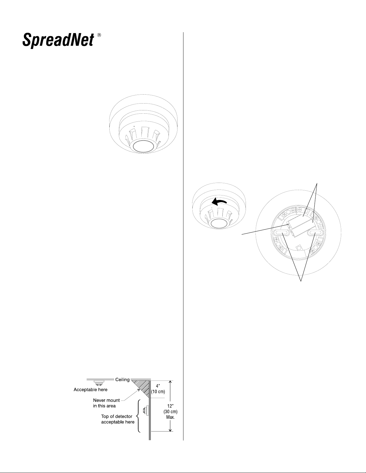
manuals.online logo
Brands
  1. Home
  2. •
  3. Brands
  4. •
  5. IntelliSense
  6. •
  7. Smoke Alarm
  8. •
  9. IntelliSense SpreadNet SN982-Smoke User manual

IntelliSense SpreadNet SN982-Smoke User manual

1
Figure 1
Mounting location
considerations
TheSN982-SMOKEisasystemtype
smoke detector, designed for open
area protection. The unit combines
a SpreadNet®Spread Spectrum
wirelesstransmitterwithaphotoelec-
tric smoke detector.
Spread Spectrum technology pro-
videshigherpower,lower noise, less
interference, and longer range than
single frequency transmitters. The
RFtransmitterisfullysupervised, en-
suring reliable communications.
WHERE NOT TO PLACE THE DETECTOR
When selecting a mounting location, avoid areas containing large
metal surfaces, which could affect the RF transmitter. Always test
the transmitter prior to permanently mounting it to verify signal
reception.
Avoid placing the SN982-SMOKE in areas where smoke or steam
mayaffectoperation,suchaskitchens, bathrooms,nearwoodstoves
or furnaces. Also avoid areas such as garages, attics, and areas
where ambient temperature may exceed 100° F (37.8° C).
• Spread spectrum technology
• Up to 100 mW transmitter
power
• EEPROM memory
• Lithium batteries included
• Simple installation
• Removable, cleanable
smoke chamber
• Magnetic detector functional
operation check
• Vandal resistant security
locking feature
• Highly stable operation
• RF/Transient protected
FEATURES
DETECTOR PLACEMENT
The SN982-SMOKE Photoelectric Smoke Detector is designed
to be either ceiling or wall mounted. When ceiling mounting the
SN982-SMOKE, be sure to mount the detector near the center of
the room, if possible. Do not place the detector less than 4" (10
cm) from the nearest wall. If wall mounting, do not mount within 4"
(10 cm) of the ceiling. (See Figure 1.)
Detector placement should be established by qualified person-
nel, such as a Fire Alarm Technician certified by the National In-
stitute for Certification in Engineering Technologies (NICET), or a
Licensed Fire Protection Engineer. Location and spacing of de-
tectors depends upon such factors as ceiling height, area to be
covered, air flow conditions, and other conditions which may af-
fect response time. Additional information regarding detector
placement may be found in the National Electrical Manufacturers
Association (NEMA) Guide for the Proper Use of System Smoke
Detectors as well as NFPA 72.
MOUNTING
The SN982-SMOKE will mount directly to the wall or ceiling.
Do NOT mount on any type o gang box.
The SN982-SMOKE must be programmed prior to permanent
mounting. Re er to the PROGRAMMING THE TRANSMITTER
section below.
To mount the SN982-SMOKE, remove the detector head rom
the base by turning the head counterclockwise. Mount the de-
tector base using #6 - #8 (M 3.5 - M 4) mounting screws. (See
Figure 2 below.)
Mounting Holes
Figure 2
SN982-SMOKE assembly,
top iew (head remo ed)
The SN982-SMOKE comes equipped with a vandal resistant
locking eature. The Locking Screw is a 1.5mm Allen head (hex-
agonal) set screw. A ter installing the detector head, turn the
locking screw clockwise six to eight turns and then check that
the head is locked in position.
PROGRAMMING THE TRANSMITTER
In order to program the SN982-SMOKE, the batteries must be
activated and the detector head must be itted to the base.
The ollowing procedure outlines the steps or programming
the detector:
1 - Separate the detector head rom the base as described in
the MOUNTING section.
2 - Remove the Battery Tab (see Figure 2 or Tab location).
3 - Replace the detector head, as described above. This will
enable the transmitter circuitry.
IMPORTANT: There is no power to the transmitter with the
detector head removed.
Battery Tab
(Remove prior to use)
Batteries (2 required)
Model SN982-SMOKE
RF Photoelectric Smoke Detector
Installation Instructions
2
PROGRAMMING THE TRANSMITTER (continued)
4 - Remove the back cover (dust cover) rom the detector base
by inserting a small screwdriver into one o the slots at the
edge and gently li ting the cover.
5 - To release the Transmitter PCB, press the PCB Retaining
Latch and gently li t the board out o the base. Be areful
not to bend the antenna.
6 - Connect the SN900-PROG RF Programmer to J1 on the
transmitter PCB. (See Figure 3 or location o J1.) Complete
programming in ormation may be ound in the SN900-PROG
Programming Manual (P/N 5-051-136-00).
7 - A ter programming the transmitter, care ully replace the PCB.
Fill out the Transmitter Device ID Label (supplied with the
unit) and apply the label to the rear dust cover.
Figure 3
SN982-SMOKE rear iew,
(Back Co er and Trans-
mitter PCB Remo ed)
P. CODE: The System Property Code.
CHANNEL: Spread Spectrum selected by
the system.
ZONE: Control panel zone number associ-
ated with the transmitter.
DEVICE: The number of the device associ-
ated with the zone.
CHECK-IN: Supervisory interval (in seconds).
BATTERY: Date batteries installed.
0253
2
01
01
30
1/14/99
P. CODE
CHANNEL
ZONE
DEVICE
CHECK-IN
BATTERY
NOTE: Only one (1) SN982-SMOKE may be connected per
zone. When using the SN910-RCVI/O, all devices
must use Device #1.
APPLICATIONS
The SN982-SMOKE can be used in all areas where Photoelectric
Smoke Detectors are required. It is best suited or smoldering ires.
CAUTION: The SN982-SMOKE is not an alarm signal-
ling device. For proper operation, this detector MUST
be used in conjunction with an alarm signalling system,
consisting o the SN912-RCV, SN913-I/O, an approved
control panel and approved signalling device(s).
OPERATION
The detector uses an LED light source and silicon photodiode
receiving element. In normal conditions, the light rom the puls-
ing light source does not strike the photodiode. In the event o
a ire, smoke enters the detector chamber, causing light rom
the LED source to be re lected o the smoke particles to the
photodiode. The amount o light received is proportional to
the density o the smoke particles.
The received light is converted into an electronic signal. The
signal is compared to a ixed re erence. When three consecu-
tive signals exceed the re erence level within a speci ied time
period, an alarm signal is generated.
TESTING THE INSTALLATION
When installing the SN982-SMOKE, you can per orm a unctional
test o the alarm circuitry by using a test magnet. The test is per-
ormed as shown in Figure 4 below.
Test Magnet
Figure 4
Testing with the Test Magnet
The SN982-SMOKE must be programmed and operational prior
to testing. Remember, alarm signals are annunciated by the con-
trol panel, not the detector.
Place the test magnet as shown in Figure 4 or at least 15 sec-
onds. The system should signal an alarm condition.
NOTE: An alarm signal generated using the test magnet does
not assure an alarm response in the event o a hazard-
ous ire condition. Additionally, this test does not check
the ability o smoke to enter the chamber, nor accurately
test the sensitivity o the device.
Transmitter Devi e ID
The ollowing procedure is recommended or mounting the label:
1 - Replace the back cover on the SN982-SMOKE.
2 - Remove the adhesive backing rom the label and place
the label on the back cover.
3 - Mount the detector as described previously.
A sample o a completed Transmitter Device ID label is shown
below:
3
TESTING THE INSTALLATION ( ontinued)
To test the ability o smoke to enter the chamber, you may use
a smoldering punk stick or a cotton wick. Hold the smoke
source near the smoke entry openings o the detector and di-
rect the smoke into the detector. Continue or up to 20 sec-
onds or until an alarm signal occurs. The actual time required
will depend upon air low conditions surrounding the detector.
This is a go/no-go test and is not an accurate test o the sensi-
tivity o the detector. Be sure to properly extinguish the smoke
sour e following the test!
General:
Average Current:
28 uA
Alarm Current:
3.2 mA for 2 seconds maximum
Dimensions:
5.9" Diameter, 2.6" H
15 cm Diameter, 7.0 cm H
Weight:
10.5 oz (292 g) without batteries
13 oz (363 g) with batteries
Operating Temperature:
32° to 100° F (0° to 37.8° C)
Relative Humidity:
0-95% (non-condensing)
Rated Voltage:
6.4-7.2 VDC (6.8 VDC nominal)
Input Power:
Two 3.6 VDC lithium batteries (supplied)
Replacment Battery Model:
SAFT Model #LS14500
Compliance:
UL Listed, Category UROX, File S6022
Smoke Head:
Type:
GaAIAs infrared emitting diode
Sampling Interval:
3.5 seconds
Switch On Time:
5 seconds
Test Feature:
Use magnet: equivalent to 4-6% obscuration
Sensitivity:
2.5% / Ft (+1.5% / Ft: -1.5% / Ft)
Compliance:
Recognized UL Component Category UROX S5022
RF Transmitter:
RF Power Output:
Up to 100 mW
Check In Report Interval:
30-300 seconds (Progammable in 10 second intervals)
Operating Frequency:
902 MHz - 928 MHz Spread Spectrum
RF Emission Compliance:
FCC Part 15; FCC Sub part C
IC
NOTE: Batteries should be replaced following a Low
Battery indication or every 12 months,
whichever occurs first.
SPECIFICATIONS
SENSITIVITY MEASUREMENT
The sensitivity o the SN982-SMOKE smoke detector may be de-
termined using a Gemini 501 smoke detector tester. Re er to the
Operation Manual supplied by Gemini Scienti ic Corp. and to Apollo
Technical Bulletin PP2071/1999 on how to set to the instrument to
carry out the test.
Sensitivity measurements should be per ormed on each detector
in accordance with the requirements listed in NFPA 72 Chapter 7.
MAINTENANCE
Under normal circumstances, the minimum maintenance require-
ments o the SN982-SMOKE consists o an annual cleaning o dust
rom the detector head with a vacuum cleaner. (More requent clean-
ing may be required in dusty areas.) Additional guidelines on de-
tector maintenance requirements may be ound in NFPA 72 Chapter
7 and the NEMA Guide for the Proper Use of System Smoke Detec-
tors.
NOTE: Be sure to alert all concerned parties whenever any test-
ing or maintenance o the ire alarm system is to occur.
CAUTION: Removing the head rom the SN982-SMOKE
smoke detector will disable the transmitter, resulting in
a Failure-to-Communicate indication at the control panel.
IntelliSense and SpreadNet are registered trademarks o
Honeywell, Inc.
All other trademarks are the property o their respective owners.
Copyright 2001 IntelliSense. All Rights Reserved
5-051-568-00 Rev. B
FCC NOTICE
The Model SN982-SMOKE Smoke Detector Transmitter generates and uses
radio requency energy. I not installed and used in accordance with the man-
u acturer's instructions, it may cause inter erence to radio and television recep-
tion. The SN982-SMOKE Smoke Detector Transmitter has been tested and ound
to comply with the speci ications in Part 15 o FCC Rules or Class B Computing
Devices and FCC Part 15 Subpart C, Speci ications or Intentional Spread
Spectrum Radiators.
I this equipment causes inter erence to radio or television reception - which can
be determined by turning the equipment on and o - the installer is encouraged
to correct the inter erence by one or more o the ollowing measures: 1) Reorient
the antenna o the radio/television. 2) Relocate the SN982-SMOKE transmitter
with respect to the radio/television.
I necessary, the installer should consult an experienced radio/television tech-
nician or additional suggestions.
CAUTION: IntelliSense does not support ield changes or modi ications to any
o the SpreadNet RF equipment unless they are speci ically covered in this manual.
All adjustments must be made at the actory under the speci ic guidelines set orth
in our manu acturing processes. Any modi ication to the equipment could void the
user's authority to operate the equipment and render the equipment in violation o
FCC Part 15, Subpart C, 15.247.
This device complies with Part 15 o the FCC Rules. Operation is subject to the
ollowing two conditions: (1) this device may not cause harm ul inter erence,
and (2) this device must accept any inter erence received, including inter erence
that may cause undesired operation.
INDUSTRY CANADA
This digital apparatus does not exceed the Class B limits or radio noise
emissions rom digital apparatus as set out in the Radio Inter erence Regulations
o Industry Canada.
This device complies with RSS-210 o Industry Canada. Operation is subject
to the ollowing two conditions: (1) this device may not cause inter erence, and
(2) this device must accept any inter erence including inter erence that may
cause undesired operation o the device.
Le présent appareil numérique n'émet pas de bruits radioélectriques dépassant
les limites applicables aux appareils numériques de Classe B prescrites dans
le Règlement sur le brouillage radioélectriques édicté par le ministère des
Industrie Canada.
4

Popular Smoke Alarm manuals by other brands

family first FFP9VH user manual

family first

family first FFP9VH user manual

Elmes Electronic MTS-166/9V quick start guide

Elmes Electronic

Elmes Electronic MTS-166/9V quick start guide

Malmbergs KD-133A instruction manual

Malmbergs

Malmbergs KD-133A instruction manual

Honeywell compact asd installation instructions

Honeywell

Honeywell compact asd installation instructions

Mircom FX-3500 Installation and operation manual

Mircom

Mircom FX-3500 Installation and operation manual

Clymac zm2 Operating and maintenance instructions

Clymac

Clymac zm2 Operating and maintenance instructions

Bentel Security ZT100P quick start guide

Bentel Security

Bentel Security ZT100P quick start guide

First Alert SC7010B user manual

First Alert

First Alert SC7010B user manual

Red Arrow SMAS-P installation instructions

Red Arrow

Red Arrow SMAS-P installation instructions

jablotron JA-85ST quick start guide

jablotron

jablotron JA-85ST quick start guide

bolid DIP-34PA-03 quick start guide

bolid

bolid DIP-34PA-03 quick start guide

Kidde KN-SMFM-i user guide

Kidde

Kidde KN-SMFM-i user guide

System Sensor 2D51A Installation and maintenance instructions

System Sensor

System Sensor 2D51A Installation and maintenance instructions

BRK electronic 7010BSL manual

BRK electronic

BRK electronic 7010BSL manual

Trader BEAR BESMOKEY Installation and user guide

Trader

Trader BEAR BESMOKEY Installation and user guide

Kidde KN-COSM-BCA user guide

Kidde

Kidde KN-COSM-BCA user guide

First Alert SA500A Specification sheet

First Alert

First Alert SA500A Specification sheet

Kidde P4010ACSCO-W user manual

Kidde

Kidde P4010ACSCO-W user manual

manuals.online logo
manuals.online logoBrands
  • About & Mission
  • Contact us
  • Privacy Policy
  • Terms and Conditions

Copyright 2025 Manuals.Online. All Rights Reserved.