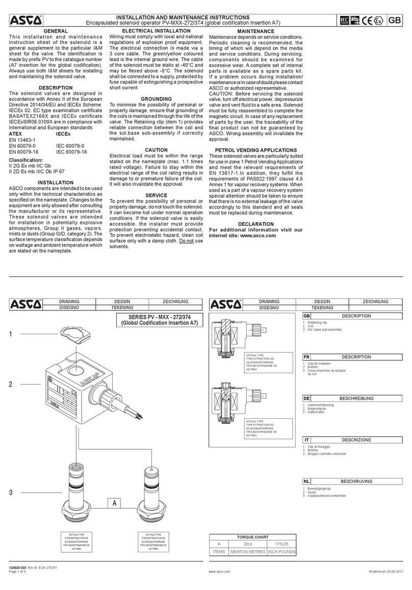
Intellitec FLEETWOOD User manual

1485 Jacobs Rd.
Deland, FL 32724
386.738.7307
P/N 53-00597-100 Rev. C 032619
www.intellitec.com
Intellitec
OWNERS GUIDE
FLEETWOOD - ELECTRONIC CONTROL CENTER
The system
offers automatic and manual control of the roof-top air
conditioners and the furnace/s in the motorhome. It
includes a number of features that help provide the
owner with the most comfortable temperature possible.
While the system is simple to operate, to fully appreciate
the complete benefits, the owner should become
familiar with the controls and their functions.
The system offers automatic control of temperature as
normally found on RV air conditioners. When in the
mode, it also controls the fan speed to
provide the cooling required, at the most quiet speed.
In addition to controlling the comfort level of temperature,
the system constantly monitors the current being drawn
by all the electrical appliances in the coach and will
control the air conditioners to prevent them from over-
loading the circuit breakers. Once the system turns them
off, it will keep them off as long as required and then
automatically returns them to normal operation.
The system has been designed to operate from a 120
VAC, 30 Amp service Connection of the coach to
any other power source will cause operation of
the system.
Your interface to the system is the central control panel.
There are two identical sets of controls on this panel, one
for each air conditioner and furnace.
- The temperature control is used to
select the desired temperature for each area of the
coach. Moving the control down, lowers the set
temperature. The approximate range of these controls is
50 to 90 degrees.
- The function switch is used to select the
desired function of the system, heating or cooling.
“ ” - The green “ON” LED indicator will be on at all
times when the function switch is set to operate the
system for either heating or cooling.
“ ” - The red “SHED” LED indicator will be on steady
when the temperature conditions are demanding
cooling, but there is insufficient power available to
operate all the functions. The indicator will be blinking
when the system is holding off the compressor for the two
minute shut-down period.
ELECTRONIC CLIMATE CONTROL
AUTOMATIC
ONLY.
improper
If there is only 20 Amp service available,
load management must be done manually by the owner
and only one air conditioner can be operated at one time.
TEMPERATURE
FUNCTION
ON
SHED
GETTING TO KNOW THE SYSTEM
CONTROLS
INDICATORS
A/C1 A/C2
1
00-00591-000 Master Controller
00-00597-000 Display Panel

1485 Jacobs Rd.
Deland, FL 32724
386.738.7307
P/N 53-00597-100 Rev. C 032619
www.intellitec.com
Intellitec
OWNERS GUIDE
FLEETWOOD - ELECTRONIC CONTROL CENTER
COOLING
AUTO COOL.
HEATING
HEAT
Auto Cool
HEAT
OFF
LOW FAN
HIGH FAN
LOW COOL
HIGH COOL
AUTO COOL
AUTOMATIC SHEDDING
To operate the air conditioners, first select a desired
temperature for the A/C1 (front) and A/C2 (rear) of the
coach. Then select the cooling functions desired with the
function switches. The normal setting of these switches
will be Once the system cools the coach
to the set point, the temperature can be adjusted to suit
your individual preference.
To operate the furnace/s, first select a desired
temperature. A good starting point is about mid-point of
the range. Then select the setting on the function
switch. Once the system heats the coach to the set point,
the temperature can be adjusted to suit your individual
preference.
The following describes the intended purpose for each of
the Function Switch settings. Four of the settings are
used to manually control the air conditioner functions.
The setting is the most useful setting for
cooling as it provides control of both the fan
speed and the temperature.
- In HEAT, the furnace/s will operate to maintain
the set temperature in the coach.
- The air conditioners and furnace/s are off. To
minimize unnecessary battery drain, the function
selector should be left in this position when neither heat,
nor cooling are desired.
- LOW FAN operates the fan only, on low
speed. The thermostat is operative in this mode,
load shed is active.
- HIGH FAN operates the fan only on high
speed. The thermostat is operative in this mode,
load shed is active.
- LOW COOL operates the fan continuously
on low speed, the compressor is controlled by the
thermostat. Load shed is active.
- HIGH COOL operates the fan
continuously on high speed, the compressor is controlled
by the thermostat. Load shed is active.
- AUTO COOL provides automatic control
of both the fan speed and temperature. The speed of the
fan and temperature are controlled by the thermostat
setting. When the coach temperature is higher than the
thermostat setting, the compressor will run and the fan
will operate at high speed to provide maximum cooling.
As the temperature cools to the set point, the fan will
switch to low speed and the compressor will continue to
run to provide cooling. Once the set temperature is
reached, the fan will continue to operate at low speed
and the compressor will go off. If the temperature in the
coach drops below the set point, as would happen during
a cool evening, the fan will stop.
As the temperature rises again, the fan will come on at
low speed. If the temperature rises further, the
compressor will come on to provide cooling. As the
temperature rises still further, the fan will switch to high
speed to provide maximum cooling.
The Climate Control System allows both air conditioners
to operate at the same time, as long as there is enough
current available. In any cooling setting of the
FUNCTION switch, the current drawn by the electrical
loads in the coach is constantly monitored. When there
isn’t enough current available to operate both units, the
system will “shed” the air conditioners as necessary to
prevent the circuit breakers from opening.
When both air conditioners are operating, they draw
approximately 26 Amps. Since there is only 30 Amps
available form the shore power outlet, there is 4 Amps left
to operate all the other electrical loads, including the
refrigerator and converter.
FUNCTION SWITCH SETTINGS
automatic
NOT
NOT
2

1485 Jacobs Rd.
Deland, FL 32724
386.738.7307
P/N 53-00597-100 Rev. C 032619
www.intellitec.com
Intellitec
OWNERS GUIDE
FLEETWOOD - ELECTRONIC CONTROL CENTER
AUTOMATIC SHEDDING
SHED
SHED
TYPICAL OPERATION
GENERATOR OPERATION
(continued)
work
maximum
shedding
If other appliances are turned on, the total current draw
could exceed 30 Amps. This would normally cause the
circuit breaker to open.
The Climate Control System however, monitors the total
current drawn by all the loads in the coach. If the total
draw exceeds 30 Amps, it will begin to turn off the air
conditioners to keep the total draw to less than 30Amps.
The turn off sequence will be as follows:
1. Rear (A/C2) compressor (if running)
2. Front (A/C1) compressor (if running)
3. Rear (A/C2) Fan
4. Front (A/C1) Fan
When this happens, the indicator/s on the
thermostat will be lit continuously to indicate the over-
load. When the total current draw drops below the point
that will allow the air conditioners to return to normal
operation, the indicator will go out and they will be
brought back on in the reverse sequence.
When a compressor is shut off, it will always be held off
for at least two minutes, to prevent it from starting into a
high load. If there is enough current to operate an air
conditioner, but it hasn’t been off for the required two
minutes, the indicator will blink. When the two
minutes has passed, the compressor will come back on
and the indicator will be out.
If the current remains above the level that would allow
operation of both air conditioners for more than a half
hour, the system will switch compressors and operate the
other one until it’s thermostat is satisfied, or a half hour
passes. If either air conditioner is turned off, the system
will continue to work by shedding the remaining air
conditioner.
In actual use, all this automatic “ ” will be hardly
noticeable to you. It’s benefit is that you will have
the amount of cooling and comfort available to
you without tripping circuit breakers.
As an example of how the system works, let’s say that the
air conditioners are running; you decide to make coffee in
the electric coffee pot and toast in the toaster at the same
time. The total current will exceed 30 Amps. The system
senses this current and begins the air
conditioner compressors. It will first turn off the rear air
(A/C2) conditioner compressor. If it was not running,
then the front (A/C1) compressor will be turned off.
When either the coffee maker or the toaster go off, which
drops the current to a level that will allow the air
conditioner to come back on, and at least two minutes
have past since the air was turned off, it will be turned
back on again. This process goes on continuously.
Operation of the system from the generator is similar to
operating from shore power. The controls operate in the
same manner. However, the generator is capable of
operating both air conditioners as well as a few
appliances at the same time. Therefore, when the
generator is running, the front (A/C1) air conditioner is
operated directly from the generator and it will not be
shed. The rear (A/C2) air conditioner will still be
controlled as if it were operating from shore power.
The generator is sized to operate both air conditioners,
but it will not start them at the same time. To prevent this
from happening, there are two built-in functions. First,
when the power from the generator is first applied to the
system, the power is delayed to the front (A/C1) air
conditioner by about 30 seconds to let the generator
warm up. After the first unit is turned on, there is
approximately another minute delay before the rear
(AC2) unit is turned on. This lets the generator get the
front (A/C1) unit running normally before trying to start
the rear (A/C2) unit.
To prevent the two compressors from ever starting at the
same time, the system always provides at least ten
seconds between compressor starts, regardless of how it
happens.
always
3

1485 Jacobs Rd.
Deland, FL 32724
386.738.7307
P/N 53-00597-100 Rev. C 032619
www.intellitec.com
Intellitec
OWNERS GUIDE
FLEETWOOD - ELECTRONIC CONTROL CENTER
Symptom
"ON" indicator won't come on
"ON" indicator on, air conditioner not cooling
"ON" indicator on, "SHED" indicator on, air
conditioners not cooling.
"ON" indicator on, "SHED" indicator blinking, air
conditioner not cooling.
Check Function Switch setting. Should be set at an air
conditioner or heat setting.
Check 5 Amp, 12 volt fuse in distribution panel.
Check Function Switch setting. Should be set at a
cooling setting (Low Cool, High Cool, Auto Cool)
Check Temperature setting. Move thermostat down for
more cooling.
Check 120 volt circuit breakers in distribution panel.
Reset if necessary.
Current draw too high. Turn off unnecessary
appliances to reduce current draw.
Air conditioners not off long enough. Wait two minutes.
Be sure coach is plugged in to "live" outlet.
Possible Cause
TEST SWITCH
TEST
TEST TEST
HIGH COOL
HIGH COOL
do not
SHORT INDICATOR
The system is equipped with a switch that helps locate system problems and can be used to manually operate an air
conditioner when that occurs. This switch is located on the control module between the connectors. The control module is
typically located under the refrigerator, behind the distribution panel.
The switch is a three-position slide switch located on the center, front edge of the control box. It is marked on
the box label. The normal setting of this switch is in the center position.
Moving this switch to the left will operate (A/C1) the front air conditioner continuously, in the mode. Moving
the switch to the right, will operate (A/C2) the rear air conditioner continuously in the mode. If the air
conditioners operate with this switch, the problem is in the air conditioner, or power being supplied to it.
This switch can be used to manually operate the air conditioners in the event of a system failure.
The Short Indicator is an LED located on the edge of the control module. If the system is not operating properly and this
indicator is ON, there is a short in the wiring to the air conditioners. When this indicator is ON, neither air conditioner will
operate. The problem can be localized by unplugging the four-pin connectors feeding each air conditioner. Unplugging
one, or the other should make the indicator go out. The other air conditioner should then operate normally. Refer the
shorted wiring problem to your dealer to locate and repair the short.
4
Other Intellitec Control Unit manuals
