Intellitec W-GV/2 User manual

V1, March 2015
INSTALLATION MANUAL
W-GV/2, W-GV/3, W-GV 8 and W-GV 10
genverters for mobile use
WHISPERPOWER BV
Kelvinlaan 82
9207 JB Drachten
Netherlands
Tel.: +31-512-571550
Fax.: +31-512-571599
www.whisperpower.com
Art.nr. 40200991

CONTENTS
2W-GV/2, W-GV/3, W-GV 8 and W-GV 10 — March 2015 — EN
CONTENTS
1 INTRODUCTION .......................................................................................................................................................................... 3
1.1 Use of this manual................................................................................................................................................................ 3
1.2 Validity of this manual.......................................................................................................................................................... 3
1.3 Installation parts................................................................................................................................................................... 3
1.4 Genverters on vehicles ......................................................................................................................................................... 4
2 INSTALLATION ............................................................................................................................................................................ 5
2.1 General ................................................................................................................................................................................. 5
2.2 Location................................................................................................................................................................................ 5
2.3 Protection against dirt, sand and bad weather conditions................................................................................................... 5
2.4 Sound and vibration reduction............................................................................................................................................. 5
2.4.1 Further recommendations................................................................................................................................. 5
2.5 Ventilation ............................................................................................................................................................................ 6
2.6 Connections.......................................................................................................................................................................... 6
2.7 Fuel supply............................................................................................................................................................................ 7
2.7.1 Fuel tank ............................................................................................................................................................ 7
2.7.2 Fuel lift pump..................................................................................................................................................... 7
2.7.3 Fuel pipes........................................................................................................................................................... 7
2.7.4 Fuel filters .......................................................................................................................................................... 7
2.8 Radiator cooling ................................................................................................................................................................... 8
2.8.1 General instructions........................................................................................................................................... 8
2.8.2 How and where to mount the radiator.............................................................................................................. 8
2.8.3 Bottom-mounted radiator ................................................................................................................................. 8
2.8.4 Side-mounted radiators ..................................................................................................................................... 8
2.8.5 Roof-mounted radiators .................................................................................................................................... 8
2.8.2 How and where to mount the expansion tank .................................................................................................. 8
2.9 Dry exhaust system .............................................................................................................................................................. 9
2.9.1 General remarks ................................................................................................................................................ 9
2.9.2 The standard dry exhaust system .................................................................................................................... 10
2.9.3 Installation of the exhaust ............................................................................................................................... 10
3 ELECTRICAL INSTALLATION ....................................................................................................................................................... 11
3.1 Digital Diesel Control system.............................................................................................................................................. 11
3.2 Remote control................................................................................................................................................................... 11
3.3 Acoustic alarm or warning lamp......................................................................................................................................... 11
3.4 Connection for emergency stop / fire alarm switch ........................................................................................................... 11
3.5 Automatic starting and stopping ........................................................................................................................................ 12
3.5.1 General ............................................................................................................................................................ 12
3.5.2 Start/stop by external switch........................................................................................................................... 12
3.6 Starter battery .................................................................................................................................................................... 12
3.7 Other recommendations and warnings.............................................................................................................................. 12
3.8 Alternating current............................................................................................................................................................. 13
3.9 Fuse .................................................................................................................................................................................... 13
3.10 Grounding........................................................................................................................................................................... 13
3.11 Cable................................................................................................................................................................................... 13
4 INSTALLATION SUMMARY ........................................................................................................................................................ 14
4.1 General ............................................................................................................................................................................... 14
4.2 Commissioning table .......................................................................................................................................................... 14
4.3 Technical data .................................................................................................................................................................... 14
4.4 Specification of the accessoiries......................................................................................................................................... 14
4.5 Exhaust kit .......................................................................................................................................................................... 15
4.6 Fuel kit ................................................................................................................................................................................ 16
4.7 Battery installation kit ........................................................................................................................................................ 16
5 DIAGRAMS & DRAWINGS ......................................................................................................................................................... 17
5.1 System diagrams ................................................................................................................................................................ 17
5.2 Mechanical drawings.......................................................................................................................................................... 18
6 OTHER PRODUCTS FROM WHISPERPOWER............................................................................................................................... 19

INTRODUCTION
W-GV/2, W-GV/3, W-GV 8 and W-GV 10 — March 2015 — EN 3
1 INTRODUCTION
1.1 USE OF THIS MANUAL
This manual serves as a guideline for the safe and effective
installation of the WhisperPower two and three cylinder
genverters for mobile applications.
It is obligatory that every person who is involved with the
installation of the genverter must be completely familiar with
the contents of this manual, and that he/she carefully follows
the instructions contained herein.
To ensure reliability and durability of the equipment, it is very
important that the installation is carried out with the utmost
care and attention. To avoid problems, such as temperature
problems, noise levels, vibration, etc. the instructions set out in
this manual must be followed and all installation work must be
carried out only by qualified, authorized and trained personnel,
consistent with the locally applicable standards and taking into
consideration the safety guidelines and measures (Chapter 2 of
the user’s manual).
The information, specifications, illustrations and statements
contained within this publication are given with our best
intentions and are believed to be correct at the time of going to
press.
Our policy is one of continued development and we re-serve
the right to amend any technical information without prior
notice.
Whilst every effort is made to ensure the accuracy of the
particulars contained within this publication neither the
manufacturer, distributor, or dealer in any circumstances shall
be held liable for any inaccuracy or the consequences thereof.
Keep this manual in a secure place!
1.2 VALIDITY OF THIS MANUAL
All of the specifications, provisions and instructions contained
in this manual apply solely to standard versions of the two and
three cylinder genverters delivered by WhisperPower.
This manual is valid for the following models:
Refer to the user’s manual for identification of the generator
set. For other models see our website:
www.whisperpower.com.
WARNING!
During installation and commissioning of the
genverter, the Safety Guidelines & Measures are
applicable at all times. See Chapter 2 of the user’s
manual.
WARNING!
A warning symbol draws attention to special
warnings, instructions or procedures which, if
not strictly observed, may result in damage or
destruction of equipment, severe personal injury
or loss of life.
DANGER!
This danger symbol refers to electric danger and
draws attention to special warnings, instructions
or procedures which, if not strictly observed,
may result in electrical shock with possibly
severe personal injury or loss of life.
WARNING!
Before working on the system read the safety
instructions in the user’s manual.
1.3 INSTALLATION PARTS
Besides the parts that are included with the delivery you need
at least the parts listed in 4.4 to install the genverter. Please
note that this listing may not be complete, as every installation
differs from the other. Oil is not included in the supply. Refer to
the user’s manual for the right specifications.
Part no.
Description
41001120
41001320
41001220
41001420
2-cylinder genverter (Kubota) for mobile use
3-cylinder genverter (Kubota) for mobile use
2-cylinder genverter (Mitsubishi) for mobile use
3-cylinder genverter (Mitsubishi) for mobile use
INTRODUCTION
4W-GV/2, W-GV/3, W-GV 8 and W-GV 10 — March 2015 — EN
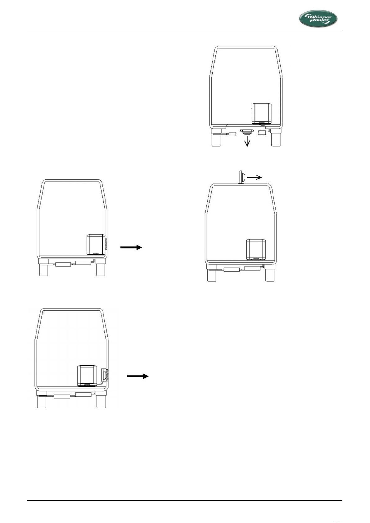
1.4 GENVERTERS ON VEHICLES
On vehicles the engine is cooled by a radiator with an electric
(12V) driven fan. Standard the cooler radiator is in the canopy
for mounting the genverter below the vehicle in the open air.
When the genverter is mounted inside the vehicle the radiator
should blow out air through the wall (Figure 1). When this is not
possible the radiator can better be mounted outside the canopy
and outside the vehicle. This can be in the side, below or on top
or of the vehicle.
The exhaust is of the dry type and includes a stainless steel
flexible bellow and high quality mufflers. Also the exhaust can
be at the side, below or on top of the vehicle.
IT IS VERY IMPORTANT TO EVALUATE ALL PRO’S AND CONT’S
BEFORE MAKING A CHOICE HOW TO SET UP THE INSTALLATION.
Figure 1: Radiator inside the canopy blows air out through the
side of the vehicle
Figure 2: Radiator mounted in the side of the vehicle
Figure 3: Radiator mounted below the vehicle
Figure 4: Radiator mounted on the roof of the vehicle

INSTALLATION
W-GV/2, W-GV/3, W-GV 8 and W-GV 10 — March 2015 — EN 5
2 INSTALLATION
2.1 GENERAL
To ensure reliability and durability of the equipment, it is very
important that the installation is carried out with the utmost
care and attention. To avoid problems, such as temperature
problems, noise levels, vibration, etc. the instructions set out in
this manual must be followed and all installation work must be
carried out professionally.
2.2 LOCATION
When looking for a proper place for a genverter in a vehicle all
relevant aspects have to be taken into account
Accessibility
Solid foundation
Space to mount the radiator (refer to 2.8)
Space to mount the exhaust (refer to 2.9)
A route to fit the fuel lines
The air flow through the genset (refer to 2.6)
Because of their small dimensions, WhisperPower genverters
can be installed in tight locations. Please consider that even
almost maintenance-free machinery must still remain
accessible.
When selecting the location for the genverter, make sure there
is sufficient room to carry out any maintenance work. The unit
must be easily accessible on the service side.
All models can be serviced from one side. Oil filling can be done
on the service side and on the top. The top of the engine
(rocker cover) has to be accessible for adjustment of the valve
clearance.
Please also note that in spite of the automatic oil pressure
switch the oil level must checked regularly.
2.3 PROTECTION AGAINST DIRT, SAND AND BAD
WEATHER CONDITIONS
The unit can be mounted below a vehicle. However, be aware
of the bad conditions below a truck when driving in rain or
snow. Also protect the unit from a spray of water and/or mud
behind the wheels. In some territories there is sand in the air.
In such situations, it is recommended to fit the air inlet of the
engine compartment with an air inlet strainer.
Figure 5: Mounting of the WhisperPower genverter.
X = wrong, V = OK
2.4 SOUND AND VIBRATION REDUCTION
Position the genverter as low as possible in the vehicle. The
genverter is secured to the base frame inside the canopy by
means of a double flexible engine mountings system. This
frame is must be solidly mounted in the vehicle, not using
rubber mountings again. When it is possible to mount the unit
directly on the chassis of the vehicle this has advantages in
preventing vibrations by resonance.
2.4.1 Further recommendations
WhisperPower genverters are standard equipped with a sound
cover canopy. This sound cover has been designed to give
effective sound insulation. For optimum sound and vibration
dampening, the following factors should be considered.
1 Most importantly, the structure on which the genverter is
placed must be stiff. Directly below the base frame, the
structure should be supported vertically to the chassis of
the vehicle. When this is not possible horizontal structures
should be made stiff by additional provisions (Figure 5).
2 In larger vehicles a separate and insulated space for the
genverter will help to dampen the noise even further.
3 Avoid mounting the genverter in close proximity to thin
walls or floors that may cause resonance.
4 Sound dampening is extremely poor if the genverter is
mounted on a light weight flimsy surface such as plywood
which will only amplify vibrations. If mounting on a thinner
surface cannot be avoided, this should be at least be
reinforced with stiffening struts or ribbing. If possible,
holes should be drilled or cut through the surface to help
reduce the resonance. Covering the surrounding walls and
floors with a heavy coating plus foam will certainly
improve the situation.
5 Never connect the base of the genverter directly to walls
or tanks (Figure 5).
INSTALLATION
6W-GV/2, W-GV/3, W-GV 8 and W-GV 10 — March 2015 — EN
2.5 VENTILATION
When not in the open air below a truck, the genverter normally
draws air from the engine compartment. An engine
compartment with natural ventilation must have vent openings
of adequate size and location to enable the genverter set to
operate without overheating. To allow an ample supply of air
within the temperature limits of the genverter an opening of at
least 900 cm2is required.
A "sealed" engine compartment must have a good extraction
ventilator to maintain reasonable ambient temperatures. High
temperature of intake air reduces engine performance and
increases engine coolant temperatures. Air temperatures above
40°C reduce the engine power by 2% for each 5°C of rise. At
higher temperatures the electric output will be lower. To
minimize these effects the engine room temperature must not
exceed the outside ambient air temperature by more than
15°C.
Apply a combination of ventilators, blowers and air intake
ducting to meet the temperature limit. The air inlet ducts
should run to the bottom of the engine compartment to clear
fumes from the bottom and to circulate fresh air. Air outlets
should be at the top of the engine compartment to remove the
hottest air. An engine compartment blower should be used as
an extraction ventilator to remove air from the engine room.
In cases where it is impossible to meet the above mentioned
temperature limit by using engine compartment ventilation,
connections are to be made for an air inlet directly to the
genverter enclosure. With these connections the genverter can
be directly connected to an air duct.
Air inlets should be louvered, where appropriate, to protect the
engine room and to protect the genverter from rain and water
spray.
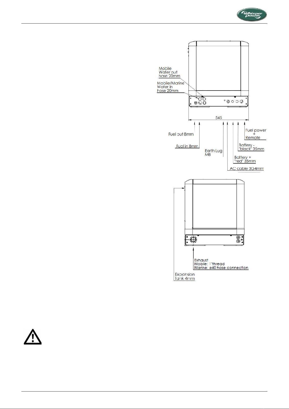
2.6 CONNECTIONS
The genverter comes with all supply lines and output cables (i.e.
electric cables, exhaust connecion, fuel lines etc.) already
connected. The supply lines are fed through the capsule’s front
base. The connections are marked as shown in Figure 6.
Refer to Section 5.1 for a graphical overview of installation and
wiring connection requirements.
All electrical connections, cable types and sizes must comply
with the appropriate national regulations. Supplied cables are
rated for ambient temperatures up to 70°C. If the cables are
required to meet higher temperature requirements, they must
be run through conduits.
ATTENTION!
Before working on the system, read the safety
instructions.
Figure 6: Genverter connections
INSTALLATION
W-GV/2, W-GV/3, W-GV 8 and W-GV 10 — March 2015 — EN 7
2.7 FUEL SUPPLY
2.7.1 Fuel tank
Fuel tanks should be made of appropriate material such as
(stainless) steel or plastic. Steel tanks should not be galvanized
or painted inside. Condensation can occur in metal tanks when
temperature changes. Therefore, water accumulates at the
bottom of the tank and provisions should be made for the
drainage of this water.
The tank will need a filling connection, a return connection and
an air ventilation connection which will require protection
against water entry.
Some official regulations do not allow connection points at the
base of the fuel tank; connections are to be made at the top of
the tank with internal tubing down to a few cm above the
bottom of the tank. When using the existing fuel tank of the car
engine, fitting should be carried out with extra care. Both a
supply line and a return line should be installed and go into the
tank from the top. Interference of the two systems (car engine
and genverter engine) should be avoided. Driving the tank
empty below the level of the suction pipe of the genverter
could make it necessary to bleed the fuel system.
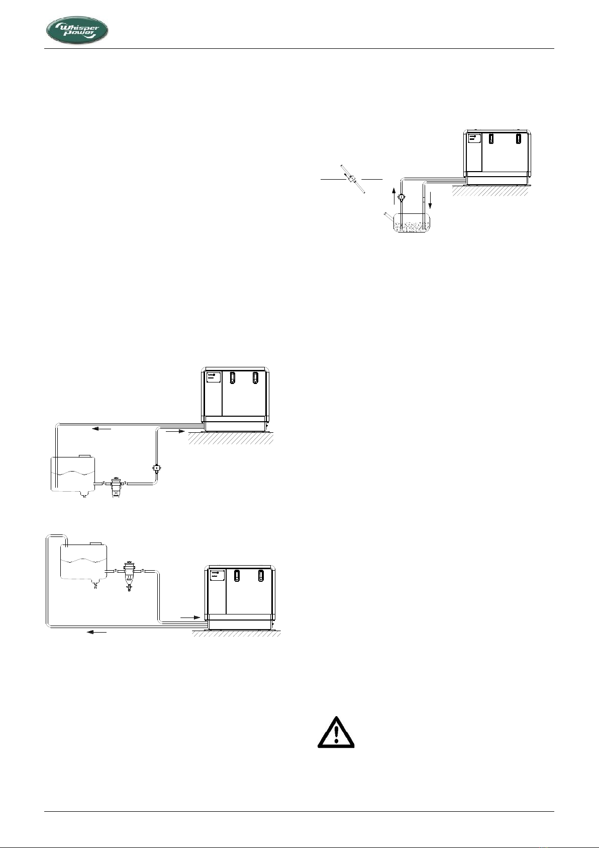
Figure 7: Fuel tank below the genverter
Figure 8: Fuel tank above the genverter
2.7.2 Fuel lift pump
The three-cylinder genverter has a built-in fuel lift pump;
therefore the tank can be installed at a lower level than the
genverter (Figure 7). The maximum suction height is 1 m. If the
pump has to lift the fuel higher than 1 m an external fuel lift
pump must be installed (art. no. 50201062 or 50202200
(noiseless model), as appropriate).
The two-cylinder genverter has an external fuel lift pump. This
should be mounted close to the tank, in an angle or vertically to
prevent air bubbles from blocking the system. As the pump
makes clicking noises, it is recommended to use rubber
mountings. If the clicking noises of the pump are not
acceptable, a noiseless pump is available as an option (Art. no.
50202200).
Figure 9: Fuel line assemblies with pump mounted vertically or
in an angle
2.7.3 Fuel pipes
When the tank is above the genverter (Figure 8) we
recommend ending the return line on the top of the tank.
When the return is on the top, siphoning of the return line is
impossible in case of a leakage. Only the fuel supply line will
need to be fitted with a fuel cock. When the tank is below the
genverter (Figure 7) we recommend ending the return line on
the bottom of the tank below the inlet of the supply line.
Both supply and return fuel pipe lines should be made of
appropriate material and have an 8 mm outer diameter. The
quality of the tubing of fuel pipes may be subject to local
regulations depending on the application of the vehicle.
The fuel pipes can be connected to the flexible hoses which are
on the genverter and are prepared to be fitted to 8 mm pipe.
The resulting fuel line complies with CE standards as well as
ISO 7840 A2.
It is important to avoid bends in the pipes, as they could trap air
bubbles. The return pipe should never be connected to the
suction pipe. The return line should be of 8 mm diameter and
go straight back via the top to the bottom of the tank. When
the return is too narrow, has too many bends and goes back to
the bottom of the fuel tank (i.e. bypassing the top), the back-
pressure may be too high. This results in irregular running of
the engine. When the engine runs irregularly, check if back-
pressure is the problem by disconnecting the return line just
outside the canopy and draining it in a canister. When the
engine runs smooth now, the return piping has to be changed.
It could also help to install a second (electrical 12V) fuel lift
pump in the supply line to increase the pressure.
2.7.4 Fuel filters
A fine fuel filter is installed which requires maintenance.
WhisperPower recommends installing an extra fuel filter/ water
fuel separator near the fuel tank.
Before starting your genverter for the first time
follow the fuel system bleeding procedure in the
user’s manual.
INSTALLATION
8W-GV/2, W-GV/3, W-GV 8 and W-GV 10 — March 2015 — EN
2.8 RADIATOR COOLING
2.8.1 General instructions
The radiators can be mounted below the floor, in the side or on
the roof of the vehicle. It is recommended to install the radiator
as close as possible to the unit. The piping should be fitted as
direct as possible.
It is very important to use good quality heat and
pressure resistant hose and fittings. Therefore it
is strongly recommended to use WhisperPower
installation kits.
2.8.2 How and where to mount the radiator
The radiator kit includes rubber mountings to prevent
vibrations from being transferred to the body of the vehicle.
Due to the differences between vehicles general instructions
are hard to give. For OEM customers, WhisperPower can supply
a customized installation kit.
When mounting the radiator it is important to take care that
the outgoing connection, which is the connection to the engine
inlet, is on the top position (Figure 15, detail A) and is
connected to the expansion tank. Also when the radiator is
mounted flat at the bottom of the vehicle the outgoing
connection is connected to the expansion tank. This is the best
way to have the system release air and to add liquid when
necessary.
2.8.3 Bottom-mounted radiator
When bottom-mounted, the radiator should not be the lowest
point of the vehicle to avoid damage.
A free flow of air should be ensured. When horizontally
mounted, the fan should be on top, causing a flow of air
downwards. Often it is possible to find a place where extra
space above the fan helps to create a free flow of air. It is
recommended to fit a shield below the radiator, catching
stones and dirt and operating as a spoiler. The distance
between the radiator and the shield should be at least 50 mm.
Sometimes it is possible to build the radiators and shield on a
sub frame that is mounted below the vehicle as a module.
MEASURES HAVE TO BE TAKEN TO PREVENT THE
HOT AIR FROM CIRCULATING AND REDUCING
THE CAPACITY OF THE RADIATORS.
Figure 10: Bottom-mounted radiators with shield
2.8.4 Side-mounted radiators
Both effective and easy is to mount the radiator in the side of
the vehicle, if possible below the level of the top of the engine.
A louvered grid should protect the radiator from rain and
objects, but must not block the airflow. The fan should be
inwards, causing the air to blow outwards. A disadvantage of
having the radiator in the side is possibly more noise from the
electric fan and a flow of air that could be felt by people passing
by.
A free flow of air should be ensured.
Figure 11: Side-mounted radiator
2.8.5 Roof-mounted radiators
The radiator on the roof is often the best option from the point
of view of keeping the noise of the fan away from people and it
will give the best result in dissipating the heat. However, this
option may conflict with the possible need to keep the vehicle
as low as possible.
Another disadvantage is that the piping has to go through the
roof which requires connections to be made waterproof. When
having the radiators horizontally mounted on the roof
(Figure 12) enough space (50 mm) should be between the roof
and the radiator fan to have a free flow of air. When the
radiator is roof-mounted there should be protection against
weather conditions. To avoid damage while the vehicle is
driving at high speed, the use of a spoiler may be necessary.
Figure 12: Two examples of top mount radiators
2.8.2 How and where to mount the expansion tank
When the radiators are above the engine, the piping should be
fitted below the top of the radiators! (see Figure 13). Bends in
the piping that can trap air bubbles, should be avoided or
ventilated (see Figure 14). The expansion tank must be fitted in
the outgoing circuit of the radiator, i.e. the inlet pipe of the
engine

INSTALLATION
W-GV/2, W-GV/3, W-GV 8 and W-GV 10 — March 2015 — EN 9
Figure 13: Air traps should be avoided
Figure 14: Ventilating an air trap
Special attention should be paid to the ventilation of the
system. The expansion tank for the coolant is also used to
release air bubbles and makes it possible to add coolant into
the system in an easy way. This expansion tank should be at the
highest point of the system and mounted as high as possible.
Most cooling problems originate from air traps
blocking the circulation of the engine coolant.
We use a pressurised system. Wherever the radiators are
mounted, it is necessary to ventilate the exhaust manifold of
the engine. The exhaust manifold has an 8 mm connection for
ventilation. The delivery includes 8 mm high pressure and high
temperature resistant hose in the to connect the hose
connection on the side of the manifold to the expansion tank.
The cooling system should be filled with long-life G12+ cooling
liquid. Initially the engine cooling system can be filled via the
cap on the exhaust manifold of the engine. However, when the
radiator is above the engine one can only fill the system to the
level of the manifold. Additional filling has to be done via the
expansion tank.
Figure 15: Outgoing circuit connected to the expansion tank
When the radiator is flat mounted on the roof, the expansion
tank should be mounted a little higher. (see Figure 16, detail B).
Figure 16: Low profile radiator assembly on the roof
2.9 DRY EXHAUST SYSTEM
2.9.1 General remarks
A dry exhaust muffler system should be very effective in
silencing the exhaust when applying the right mufflers.
However, noise could be generated by vibrations in the
mufflers and be transferred to the chassis. Tacit factors like the
length of specific pipe sections could cause the noise to be
amplified. It is very difficult to take these factors into account.
Piping should not rise above the radiator inlet!

INSTALLATION
10 W-GV/2, W-GV/3, W-GV 8 and W-GV 10 — March 2015 — EN
Figure 17: Dry exhaust systems on vehicles
The standard WhisperPower exhaust kit contains the materials
to perform a professional installation. It includes a stainless
steel flexible bellow (hose) to allow for expansion and to
prevent vibrations from being transferred. Rubbers are supplied
to mount the mufflers flexible. The insulation jackets for the
flexible bellow and the resonance muffler are also very
effective in dampening vibrations. Still, additional measures
may have to be taken like an extra clamp in a vibrating section
of pipe, insulation blankets on other parts of the system and
possibly even additional mufflers.
WHEN THE EXHAUST IS LED THROUGH THE ROOF
OF A VEHICLE, MEASURES HAVE TO BE TAKEN TO
PREVENT RAINWATER FROM ENTERING THE
SYSTEM. SPECIAL RAIN CAPS ARE AVAILABLE AS
AN OPTION.
Figure 18: Ways to prevent water from getting in
A negative feature of a dry exhaust system is the heat radiated
by its components. When a dry exhaust has its outlet on the
roof, all the pipes inside the vehicle have to be insulated.
The exhaust pipes will be very hot and all
accessible pipes and mufflers are dangerous to
people when not insulated.
Some companies specialize in insulating hot pipes, and fancy
systems are available to make them look better. Alternatively,
you can wind fiberglass or rock wool around the pipes and seal
the insulation with aluminum tape.
2.9.2 The standard dry exhaust system
The standard exhaust system comprises:
On the genverter set:
An insulated exhaust bend
In the exhaust installation kit:
A stainless steel shielded flexible bellow
A resonance muffler
An absorption muffler
Clamps and rubbers
Fittings, bends and pipes to make the various
connections
Blankets for thermal and acoustic insulation.
The mufflers are high quality industrial mufflers much more
effective, robust and durable than mufflers made for
automotive use.
2.9.3 Installation of the exhaust
An essential step in determining the location of the genverter is
considering how install the exhaust. Usually, space can be
found below the vehicle to mount the mufflers. The outlet
should blow the fumes away from the doors. When the gasses
are in the flow of air blowing from the radiators this will help to
make the fumes less noticeable. Fumes must not be sucked into
the flow of air passing through the radiators. In calm conditions,
a slight smell of exhaust fumes around the vehicle is hardly
avoidable.
Bringing the exhaust to the top of the vehicle gives the best
results on noise and smell. However, pipes inside the vehicle
should be insulated and there should be a collar around the
hole in the roof to prevent the ingress of rainwater.
The mufflers should be wide apart: the resonance muffler close
to the genverter and the absorption muffler on the end of the
line, with at least 1 m pipe in between. A short pipe (30 cm)
should be on the far end after the absorption muffler. The
absorption muffler requires no particular flow direction and
could be mounted both ways. The resonance muffler, however,
should be mounted taking into account to the indication shown
on the muffler itself.
The resonance muffler should be fitted taking
into account the gas flow direction indicated.
The exhaust kit contains clamps for mounting the exhaust pipes
to stainless steel bars. These bars should be mounted to the
vehicle chassis. It is recommended to use rubber mountings
whenever possible. However, care should be taken that the
heat conducted through the brackets will not affect the rubber.
Figure 19 shows how to mount the rubber in a safe way. An
extra safeguard in steel wire or chain may be considered.
Figure 19: Mounting bracket in rubber with safeguard

ELECTRICAL INSTALLATION
11 W-GV/2, W-GV/3, W-GV 8 and W-GV 10 — March 2015 — EN
3 ELECTRICAL INSTALLATION
3.1 DIGITAL DIESEL CONTROL SYSTEM
The standard electrical control system is in 12 Volt with
negative earth. Non-earth return is available as an option. The
engine is controlled by a highly advanced microprocessor based
system: Digital Diesel Control, which has both a local control
and a remote panel.
3.2 REMOTE CONTROL
A remote control panel also containing a microprocessor is
included in the delivery, as well as a 10 m 8-pole
communication cable (Figure 20). Other lengths are available
on request. A longer (up to 30 m) cable can be connected if
required. For distances exceeding 30 m, please consult the
WhisperPower service department.
Figure 20: Remote control cable
The control panel can be mounted in the dashboard using the
plastic sawing template. For dimensions, refer to the drawings
in Chapter 5.
Two more remote control panels (slave panels) can be put in
parallel using the modular connectors on the back of the units.
Actually, the slaves are regular remote control panels offering
all functions again.
When using the factory settings, installation is very simple: just
plug in both end of the communication cable and the genverter
is ready to use (Figure 20).
3.3 ACOUSTIC ALARM OR WARNING LAMP
An external max. 150 mA relay can be connected in order to
generate an acoustic warning, light a warning lamp, etc. Be
aware of polarity as some relays have a diode inside and must
be connected plus to plus en minus to minus as indicated
(Figure 21).
Figure 21: Remote box terminals
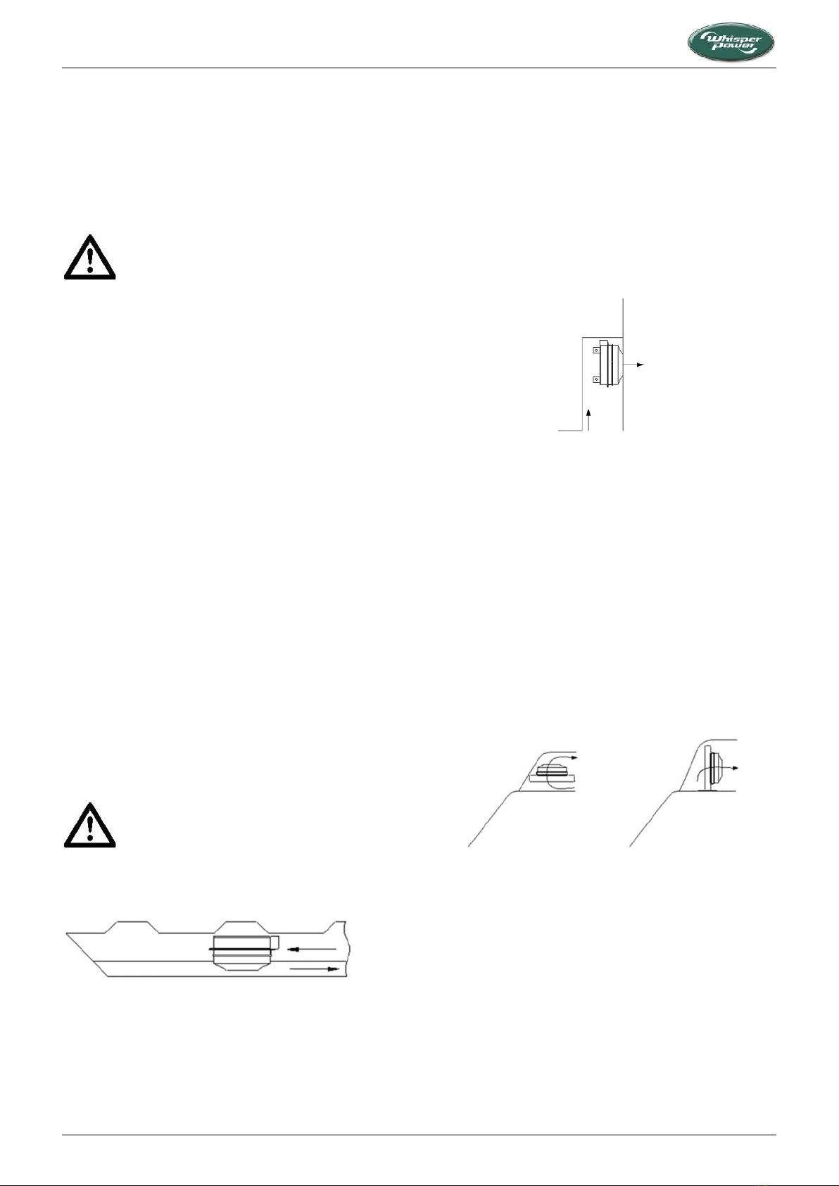
3.4 CONNECTION FOR EMERGENCY STOP /
FIRE ALARM SWITCH
Figure 22: Connection for emergency stop / fire alarm switch
To connect an emergency stop button or to stop the generator
automatically in case of a fire alarm, you can use the bypass
connection between fastons J7 and J18 on the backside of the
local control panel (Figure 22). To do so, remove this bypass
connection and then replace it by an emergency switch or a
potential free fire alarm switch with normally closed contacts.
Remove bypass
between J7 - J18
Normal operation
Alarm / emergency
local control panel
(rear view)
ELECTRICAL INSTALLATION
12 W-GV/2, W-GV/3, W-GV 8 and W-GV 10 — March 2015 — EN
3.5 AUTOMATIC STARTING AND STOPPING
3.5.1 General
WhisperPower cannot be held responsible for
damage caused by the genverter running
unattended using the auto-start/stop mode or
interval mode.
Using the auto-start/stop or interval mode, the
genverter may start unexpectedly. When working
on the electrical system, the 3 Amp fuse must be
removed from the control panel and the battery
plus cable must be removed from the battery.
Included in the delivery are warning stickers to be
applied on several parts of the electric installation
(transfer switch, distribution box, etc.) to warn
against possible automatic starting of the
genverter.
The WhisperPower Digital Diesel Control system offers several
options for automatic starting and stopping. This menu as well
as other DDC menus may be locked. For unlocking and setting
these options, refer to the APPENDIX of the DDC user’s manual.
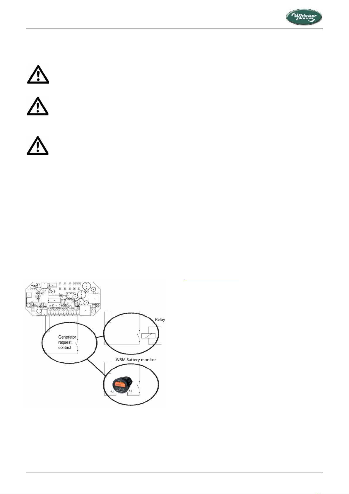
3.5.2 Start/stop by external switch
At the back of the DDC remote control panel (40209102), you
will have the possibility to connect two wires in order to allow
the genverter being started by an external signal. This requires
the optional 12-pole green connector ( part no. 50209119).
Two common options are shown in Figure 23, where the signal
can be provided by an external relay or by the Whisper Battery
Monitor (WBM).
Figure 23: Connection for start/stop by external signal
Another possibility is to monitor the voltage of a second battery
(not being the starter battery) and to start the genverter
automatically when this voltage drops below a set value. This
second battery is often called “auxiliary battery” or “service
battery”. It is referred to as BAT2 in the DDC menus. A sense
wire to monitor the second battery should be connected (check
polarity!) to the connector on the back of the remote panel
(Figure 21). The sense wires must be connected directly to the
second battery and be protected by a 3A fuse.
Settings: For settings other than the factory settings, refer to
the DDC user’s manual, especially to the APPENDIX.
3.6 STARTER BATTERY
For starting, the genverter requires a 12V starter battery of at
least 55 Ah (80 Ah recommended).
The genverter can be connected to the main engine battery or
have its own battery. We strongly recommend the use of a
separate battery for the genverter and keeping the wiring
system for the car engine and the domestic DC supply system
completely separate and individually connected to separate
batteries.
However, the negatives of all the batteries on the vehicle
should be interconnected to avoid difference in the voltage
level of the earth on different places causing trouble to
electronic devices which might be in the system.
The above recommendation is not valid for vehicles having the
starter battery of the vehicle engine or other auxiliary
equipment positive grounded. When this is the case an expert
should be consulted.
The starter battery is charged by the alternator on the engine.
However, when the genverter is not used for an extended
period of time, its control system may eventually drain the
starter battery. The WhisperPower catalogue (check
www.whisperpower.com) offers several solutions to prevent
this from happening:
A battery switch may be installed to interrupt the positive
connection.
An AC-supplied battery charger may also help to keep the
battery in good condition when the genverter is not used
(see also battery installation kit).
WhisperPower also offers high efficiency battery charging
units which are able to charge both the vehicles’s main
battery and the starter battery.
3.7 OTHER RECOMMENDATIONS AND WARNINGS
The battery should be secured for poor road conditions and the
terminals should be insulated. For extra safety the battery can
be enclosed in a wooden, plastic, fiberglass etc. (non metal)
box. Even when the earth return system is applied a negative
battery cable should be used and the vehicle should not to be
used as a conductor.
The battery cables are supplied in a standard length of 1.5 m. If
longer cables are required a larger cross sectional area should
be considered to compensate for voltage reduction.

ELECTRICAL INSTALLATION
W-GV/2, W-GV/3, W-GV 8 and W-GV 10 — March 2015 — EN 13
When two batteries are used in series to provide
a 24 Volt supply system, never take off 12 Volt
(starting) power from one of these batteries. This
will result in severe damage to both batteries
within a short time.
Disconnect the battery leads if electrical welding is to be carried
out, otherwise damage will be caused to the diodes of the
alternator.
As explosive hydrogen gases may be discharged
during charging, the battery should be located in
a well-ventilated space. Ensure that the supplied
battery cable connectors are properly fitted.
Never remove these during or shortly after
charging, as sparking may occur, igniting the
hydrogen gases.
3.8 ALTERNATING CURRENT
The electric power supplied by the genverter is
of a high voltage and dangerous to people.
Before working on the system read the sections
on safety in the users manual.
Be aware that people are not used to have AC
available on a vehicle. Put warning signs on wall
sockets and on junction boxes. Instruct non-
regular users of the vehicle. Warn maintenance
personnel of garages that do service on the
vehicle.
Generators used on vehicles that are operated in
a hazardous environment often have to fulfil
special regulations and additional measures have
to be taken accordingly.
These genverters are designed to generate power for both AC
and DC installations, depending on the type of WhisperPower
PowerCube or Power Module installed with the genverter. Be
sure that all electrical installations (including all safety systems)
comply with all regulations required by the local authorities. All
electrical safety/shutdown and circuit breaking systems have to
be installed onboard as the genverter itself cannot be equipped
with such equipment for every possible variation.
The vehicle’s power supply system should be suitable and safe
for the voltages applied and the power that will be generated.
Special attention has to be paid on dividing the system in
branches which are fused individually.
It is absolutely essential that each and every circuit in the
electrical system be properly installed by a qualified electrician.
3.9 FUSE
It is the installer's responsibility to protect the live wires
between the genverter and the PMG/DC PowerCube. Check the
electrical information on the identification plate in order to
calculate the right fuse size.
3.10 GROUNDING
The AC alternator windings are not grounded.
The housing of the alternator and all other metal parts are
grounded. The position of the earth lug is shown in Figure 6.
The electric installation in the vehicle possibly needs to be
protected against insulation failures. Methods of protection are
subject to rules that may differ depending on the use of the
vehicle and local standards. Experts in this field should be
consulted.
3.11 CABLE
For the power cable we recommend the use of 3 wire single
phase oil resistant cable with a sufficient cross sectional area.
For long cables it is recommended to apply cables with a larger
cross section (refer to ISO 13297 annex A).

INSTALLATION SUMMARY
14 W-GV/2, W-GV/3, W-GV 8 and W-GV 10 — March 2015 — EN
4 INSTALLATION SUMMARY
4.1 GENERAL
1 Mount the genverter directly, without additional vibration
dampers, on a solid surface.
2 If applicable, mount the separate cooling system.
3 Connect exhaust system.
4 Connect ‘fuel supply line’ to the water separator/ fuel
filter.
5 Connect ‘fuel return line’ to the fuel tank.
6 Connect remote panel (just plug in).
7 Connect the AC cables to the PMG/DC PowerCube.
8 Connect the battery cables to the 12V starter battery’s
positive and negative terminals.
9 If applicable, connect the power supply of the external
radiator.
10 Install a WhisperPower battery charger (optional).
4.2 COMMISSIONING TABLE
1 Check if the air inlet is sufficient.
2 Check if the cooling system for the engine is properly
installed and properly filled with G12+ cooling liquid.
When the internal radiator is used ; check if the air flow is
not blocked and that no hot air is sucked back into the
sound shield.
3 Check if the exhaust system is properly installed. Check
maximum length of exhaust hose, diameter of exhaust
piping.
4 Check all coolant connections.
5 Check the AC cables and the grounding.
6 If the genverter is installed with a WP-PMG, check if an AC
breaker is installed before or after the power source
selector. When there is only a circuit breaker, use it to
disconnect the generating set from the grid.
7 Check all DC connections, check if the battery switch/
circuit breaker is closed.
8 Open the fuel valve. Check if there are no air leaks in the
fuel supply line, and check if the lift of the fuel is less than
1 m. Check if there is no air in the water fuel separator.
9 Check the oil level and color of the oil.
10 To bleed the fuel system, push the “Start” button on the
local control (not on the remote panel) and hold at least
5 s and as long as necessary to bleed the system.
11 Start the engine by pushing the start button.
12 If the genverter is installed with a WP-PMG, check the
delay of 5 to 10 seconds in the power source selector
transfer.
13 Check voltage under ‘no load’ conditions.
14 Check if the genverter can bring the full load.
15 Check if the battery charger of the genverter is working
(max. 14.5 V).
16 Close the sound shield and check the noise level.
17 Stop the genverter and check the engine again for leakages
of oil, fuel or coolant and check the oil level again.
Installation checklist available on our website:
www.whisperpower.com.
Commissioning form available on our website:
www.whisperpower.com.
4.3 TECHNICAL DATA
Refer to the User’s Manual for an overview of general technical
specifications.
4.4 SPECIFICATION OF THE ACCESSOIRIES
Fuel filter/water separator
30 micron
Fuel inlet and return
8 mm
Flexible Exhaust bellow/ hose
1”G
Exhaust piping
1”
Exhaust mufflers
1”G
Starter battery
80 Ah

INSTALLATION SUMMARY
W-GV/2, W-GV/3, W-GV 8 and W-GV 10 — March 2015 — EN 15
4.5 EXHAUST KIT
no
qty
article no
description
1
3
50221661
U-bolt M10
2
3
50221664
Tail bracket 250 mm M10 42-60mm
4
2
50221411
Socket F/F
5
1
50230609
Absorption muffler
6
1
50221421
Union F/F
7
1
50230610
Resonance muffler
8
1
50220041
Stainless steel flexible exhaust pipe F/M
9
6
50211406
Washer M10
10
6
50211447
Spring washer
11
6
50211466
Nut M10
12
1
50221471
Bend M/F 1
TOTAL
40201325
1” DRY EXHAUST KIT
OPTIONAL MATERIALS AVAILABLE
no
qty
article no
description
dimensions
not shown
40201324
Insulation blanket kit
Generator
Dry exhaust
Not in delivery.
Recommended length
1000 mm min

INSTALLATION SUMMARY
16 W-GV/2, W-GV/3, W-GV 8 and W-GV 10 — March 2015 — EN
4.6 FUEL KIT
no
qty
article no
description
dimensions
42
1
50230091
Filter head for fuel strainer/water separator
M14x1.5 mm
43
2
50221618
Parallel male coupling
M14 - 8 mm
44
2
50221619
Parallel male coupling
M14 - 10 mm
45
2
50221620
Hose connection, outer cone
M16x1.5 mm, 8 mm
46
50230092
Filter for fuel strainer/water separator
48
4
50221522
Hose clamp, stainless
10-16 mm
49
2
50221632
Gasket ring
18x14x1.5 mm
not shown
2
50221203
Straight coupling
8 mm
not shown
2
50221252
Barbed-smooth hose nipple
8 mm
TOTAL
40230205
FUEL KIT
OPTIONAL MATERIALS AVAILABLE
no
qty
article no
description
dimensions
48
50221522
Hose clamp, stainless
10-16 mm
not shown
per m
50222020
copper fuel pipe
6x8 mm
not shown
per m
50220063
fuel hose
8x16 mm
4.7 BATTERY INSTALLATION KIT
BATTERY INSTALLATION KIT
article no
description
dimensions
61112002
WBC-Handy 20 charger 12V / 2A
157 x 33 x 34 mm
40290093
battery terminal (NEG-)
40290094
battery terminal (POS+)
40290099
M8 battery pole adapter set
40290098
isolation caps (red & black)
50214701
WP-Compact Manual Battery Switch, 300A
72 x 72 x 78 mm
40290106
INSTALLATION KIT FOR BATTERIES UP TO 100 Ah
RECOMMENDED BATTERY
article no
description
dimensions
40290061
AGM-Power 12V 80Ah Absorbed Glass Matt
350 x 167 x 180 mm
DIAGRAMS & DRAWINGS
W-GV/2, W-GV/3, W-GV 8 and W-GV 10 — March 2015 — EN 17
5 DIAGRAMS & DRAWINGS
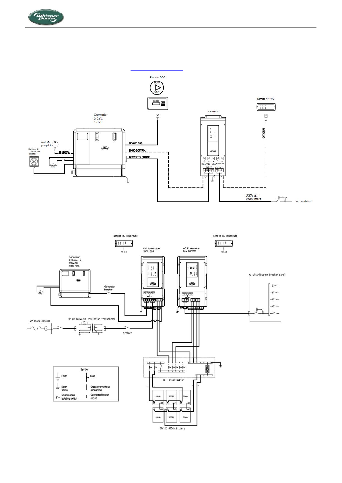
5.1 SYSTEM DIAGRAMS
NOTE: A4-size drawings can be downloaded from www.whisperpower.com.
Figure 24: Layout of genverter system with PMG
Figure 25: Example of marine genverter system with DC PowerCube and AC PowerCube

DIAGRAMS & DRAWINGS
18 W-GV/2, W-GV/3, W-GV 8 and W-GV 10 — March 2015 — EN
5.2 MECHANICAL DRAWINGS
Figure 26: Two-cylinder genverter mechanical drawings
Figure 27: Three-cylinder genverter mechanical drawings
650
600
Service side
Footprint
Footprint
Service side

WHISPERPOWER PRODUCTS
W-GV/2, W-GV/3, W-GV 8 and W-GV 10 — March 2015 — EN 19
6 OTHER PRODUCTS FROM WHISPERPOWER
WhisperPower offers a wide range of power-related products. In our PowerBook, these are arranged as follows.
Power Generation
• Diesel generators - Genverter
• Diesel generators - 3000 rpm
• Diesel generators - 1500 rpm
• Installation kits
• AC and DC belt driven generators
Power Conversion
• Sinewave inverters
• Inverter/chargers
• Battery chargers
• Monitoring and control
Power Storage
• AGM and gel batteries
• Lithium-ion batteries
• Battery-related products
• Solar energy
Power Distribution
• Shore power connect
• AC distribution
• Electrolysis prevention
• DC distribution
Hybrid power systems for power generation &
propulsion
• 24/ 48VDC based systems up to 15kW
• systems up to 300kW for super yachts
For instant and detailed information, we recommend checking our website: www.whisperpower.com.

Ref : PM-WP-GV8 Date : 5-8-2016
This manual suits for next models
3
Table of contents
Popular Inverter manuals by other brands

Westinghouse
Westinghouse WPro8500 quick start guide

Mase Generators
Mase Generators MW 180 DS owner's manual

gefran
gefran SIEIDrive ADL300 Safety user manual

Siemens
Siemens SINAMICS G180 Installation and operating instructions

Paton
Paton PSI 315 PRO user manual

Toshiba
Toshiba TOSVERT VF-AS3 instruction manual

Growatt
Growatt SPH3000 Installation & operation manual

Siemens
Siemens SINAMICS G120 Hardware installation manual

Samil Power
Samil Power SolarLake 5500TL-PM manual

Harbor Breeze
Harbor Breeze LS001-W100E2-AA-M4PK1 quick start guide

SunMaxx Solar
SunMaxx Solar TitanPower Plus-SU2 Collector installation instructions

ABB
ABB PVS800-57-0100kW-A Hardware manual


