Hioki SS7081-50 User manual

SS7081-50
Instruction Manual
BATTERY CELL VOLTAGE
GENERATOR
EN
Apr. 2020 Edition 1
SS7081C961-00 20-04H
Be sure to read this manual before using the instrument. p.2
When using the instrument for the
rst time Troubleshooting
Name and Function of Each Part p.6 Maintenance and Service p.61
Preparation Process p.11 Error Display p.61
HIOKI SS7081C961-00
99 Washington Street
Melrose, MA 02176
Phone 781-665-1400
Toll Free 1-800-517-8431
Visit us at www.TestEquipmentDepot.com

SS7081C961-00
Contents
Introduction........................................................................................................................................................ 1
Confirming Package Contents ......................................................................................................................... 1
Safety Information ............................................................................................................................................. 2
Usage Notes ....................................................................................................................................................... 3
1 Overview ..................................................................................................................................................... 5
1.1 Overview ..................................................................................................................................................... 5
1.2 Features ...................................................................................................................................................... 5
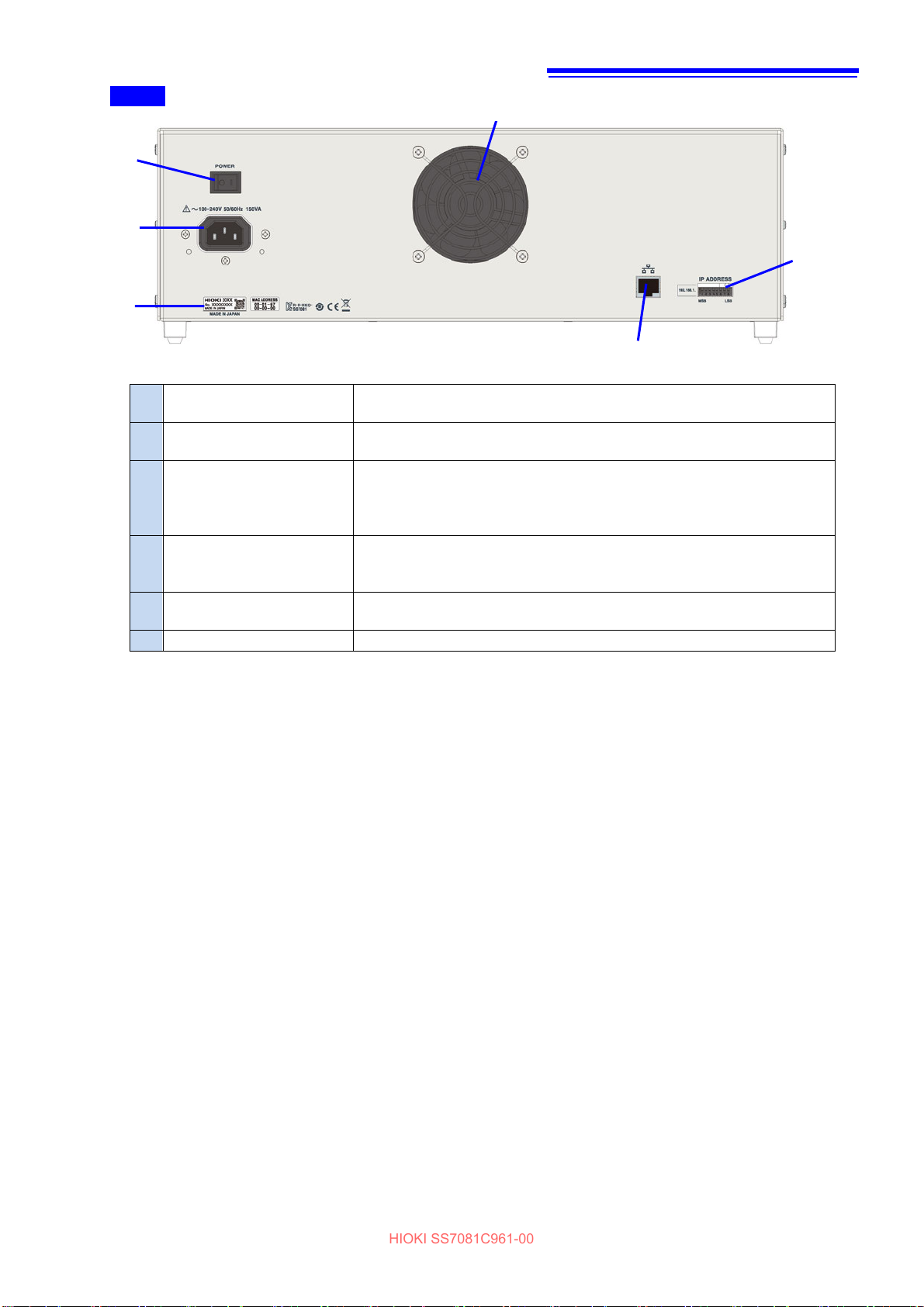
1.3 Name and Function of Each Part ............................................................................................................. 6
1.4 Lamp Display.............................................................................................................................................. 8
Channel status display.................................................................................................................................. 8
Other (error display) ...................................................................................................................................... 8
1.5 Control Methods ........................................................................................................................................ 9
2 Preparations ............................................................................................................................................. 11
2.1 Preparation Process ................................................................................................................................ 11
2.2 Connecting the Power Cord.................................................................................................................... 11
2.3 Connecting the Output Cable ................................................................................................................. 12
Connecting wires to the terminal block..................................................................................................... 12
Connecting channels .................................................................................................................................. 13
Connecting multiple instruments............................................................................................................... 14
2.4 Setting the IP Address............................................................................................................................. 15
2.5 Connecting the LAN Cable...................................................................................................................... 16
2.6 Turning the Instrument On and Off ........................................................................................................ 17
3 Generation and Measurement................................................................................................................. 19
3.1 Voltage Outputs........................................................................................................................................ 19
Output constant voltage ............................................................................................................................. 19
Changing the output voltage at high-speed (memory output function) ................................................ 20
3.2 Switching Output Terminals ................................................................................................................... 21
Output terminals for each channel ............................................................................................................ 21
Output expansion terminal (CHAIN terminal) ........................................................................................... 23
3.3 Voltage and Current Measurements ...................................................................................................... 24
Switching the current measurement range............................................................................................... 24
Acquiring stable measured values (smoothing function) ....................................................................... 25
Saving, collating, and acquiring measured values (logging function) .................................................. 26
4 Error Detection Function......................................................................................................................... 27
Overcurrent error ......................................................................................................................................... 27
Output voltage error .................................................................................................................................... 27
Abnormal temperature inside the case ..................................................................................................... 28
5 Communication Command ..................................................................................................................... 29
5.1Commands Overview .............................................................................................................................. 29
Message format............................................................................................................................................ 29
Output queue and input buffer ................................................................................................................... 32
Status byte registers ................................................................................................................................... 32
Event registers ............................................................................................................................................. 33
Communications errors .............................................................................................................................. 36
HIOKI SS7081C961-00

5.2 Message List ............................................................................................................................................ 37
5.3 Message Reference ................................................................................................................................. 39
Guide to the message references .............................................................................................................. 39
Standard commands ................................................................................................................................... 40
(1) System data command ................................................................................................................ 40
(2) Internal operation commands ..................................................................................................... 40
(3) Synchronized commands ............................................................................................................ 41
(4) Status and event control commands ......................................................................................... 41
Instrument-specific commands.................................................................................................................. 43
(1) Event status registers .................................................................................................................. 43
(2) Reading the measured value....................................................................................................... 44
(3) Output terminals........................................................................................................................... 45
(4) Output voltage .............................................................................................................................. 46
(5) Memory outputs............................................................................................................................ 47
(6) Current measurement range ....................................................................................................... 48
(7) Reading measurement data......................................................................................................... 48
(8) Smoothing function...................................................................................................................... 48
(9) Logging.......................................................................................................................................... 49
(10) Self-diagnosis ............................................................................................................................... 50
(11) Commercial power supply frequency ........................................................................................ 51
(12) Communication settings.............................................................................................................. 51
5.4 Command Examples ................................................................................................................................. 52
Set the output for all channels and acquire the measured values ......................................................... 52
Set the output for channel 1 and acquire the measured values ............................................................. 52
Simulate a wire break on channel 2 and then simulate a short-circuit on all channels.................... 52
Enable the smoothing function and set channels to the 100 µA range............................................... 52
Enable the logging function and acquire current values using the 100 µA range............................. 53
6 Specifications........................................................................................................................................... 55
6.1 General Specifications ............................................................................................................................ 55
6.2 Specifications of Input, Output, and Measurement.............................................................................. 56
6.3 Specifications of Functions.................................................................................................................... 58
6.4 Interface Specifications........................................................................................................................... 60
7 Maintenance and Service ........................................................................................................................ 61
Calibration .................................................................................................................................................... 61
Shipping Precautions.................................................................................................................................. 61
Cleaning ........................................................................................................................................................ 61
7.1 Error Display ............................................................................................................................................ 61
8 License Information ................................................................................................................................. 63
Appendix .......................................................................................................................................................... 65
Appx. 1 Internal Circuit Configuration...................................................................................................... 65
Appx. 2 Dimensions Diagram .................................................................................................................... 66
Appx. 3 Mounting the Instrument in the Rack ......................................................................................... 67
HIOKI SS7081C961-00

1
Introduction
Thank you for purchasing the Hioki SS7081-50 Battery Cell Voltage Generator. To obtain maximum performance from
the instrument over the long term, be sure to read this manual carefully and keep it handy for future reference.
Target audience
This manual has been written for use by individuals who use the product in question or who teach others to do so.
It is assumed that the reader possesses basic electrical knowledge (equivalent to that of someone who graduated
from the electrical program at a technical high school).
Accuracy
Hioki defines measurement accuracy in terms of percentages of the setting, the full scale, and the reading and
digits.
Setting
Set value
Indicates a value set so that the instrument can generate an output, such as voltage and
current, whose magnitude is equal to the set value.
“Percent of setting” means a percentage relative to the setting value.
Full scale
Maximum display value
Indicates the maximum display value of each measurement range. As for this instrument,
measurement ranges express maximum display values.
“Percent of full scale (% f.s.)” means a percentage relative to the maximum display value.
Reading
Displayed value
Indicates the value the instrument is presently displaying.
“Percent of reading (% rdg)” means a percentage relative to the displayed value.
Digit(s)
Resolution
“Digit(s) (dgt)” is a unit that represents the smallest change in the indication, which means the
figure one at the least significant digit, on the digital measuring instrument.
Confirming Package Contents
•When you open the package, carefully inspect the instrument to ensure that everything is in good condition, and
that no damage occurred during shipping. Carefully check the accessories and connectors. If the instrument seems
to have been damaged or does not work as specified, contact your authorized Hioki distributor or reseller.
•Store the instrument packaging material after opening the instrument. Use the original packaging when shipping the
instrument.
Confirm that these contents are provided.
SS7081-50 Battery Cell Voltage Generator
Accessories
Power cord
Instruction Manual (this document)
PC Application Instruction Manual (CD)
Rack-mounting frames (Rack-mounting brackets for EIA-compliant rack)
HIOKI SS7081C961-00

2
Safety Information
The instrument is designed to conform to IEC 61010 Safety Standards and has been thoroughly tested for safety prior
to shipment. However, using the instrument in a way not described in this manual may negate the provided safety
features.
Carefully read the following safety notes before using the instrument.
DANGER
Mishandling during use could result in injury or death, as well as damage to the instrument. Be
certain that you understand the instructions and precautions in the manual before use.
WARNING
With regard to the electricity supply, there are risks of electric shock, heat generation, fire, and
arc discharge due to short circuits. If persons unfamiliar with electricity measuring instruments
are to use the instrument, another person familiar with such instruments must supervise
operations.
Protective gear
WARNING
The instrument is used on a live line. To prevent an electric shock, use appropriate protective
insulation and adhere to applicable laws and regulations.
Notations
In this manual, the risk seriousness and the hazard levels are classified as follows.
DANGER Indicates an imminently hazardous situation that will result in death or serious
injury to the operator.
WARNING
Indicates a potentially hazardous situation that may result in death or serious
injury to the operator.
CAUTION Indicates a potentially hazardous situation that may result in minor or moderate
injury to the operator or damage to the instrument or malfunction.
IMPORTANT
Indicates information related to the operation of the instrument or maintenance
tasks with which the operators must be fully familiar.
Symbols affixed to the instrument
Indicates cautions and hazards. When this symbol is displayed on the instrument, refer
to the “Usage Notes” section (p.3) in the Instruction Manual for more information.
Indicates AC (Alternating Current).
Indicates the ON side of the power switch.
Indicates the OFF side of the power switch.
Symbols for various standards
Indicates the Waste Electrical and Electronic Equipment Directive (WEEE Directive) in
EU member states.
Indicates that the product conforms to regulations required by the EU Directive.
Other Symbols
*
Additional information is presented below.
(p. ) Indicates the location of reference information.
HIOKI SS7081C961-00

3
Usage Notes
Observe the following precautionary information to ensure that the instrument can be used safely and in a
manner that allows it to perform as described in its specifications.
Installing
To prevent overheating, be sure to leave the specified clearances around the instrument.
50 mm or more for the left side, right side, front, and back respectively
•The instrument should be operated only with the bottom side downwards.
•Vents must not be blocked.
•Do not tilt the instrument.
•If incorporating into a system, make sure not to exceed the instrument’s use temperature range.
CAUTION
Do not place the instrument on an unstable surface or inclined place. Dropping or knocking down
the instrument could cause bodily injury or damage to the instrument.
Handling the instrument
DANGER
Touching any of the high-voltage points inside the instrument is very dangerous.
Do not attempt to modify, disassemble, or try to repair the instrument. Doing so may cause a fire,
electric shock, or injury.
CAUTION
•To avoid damage to the instrument, avoid subjecting it to vibration or mechanical shock during
transportation and handling. Exercise particular care to avoid subjecting the instrument to
mechanical shock, for example by dropping.
•Remove the connection cable when carrying the instrument.
Handling the cables
CAUTION
•Avoid stepping on or pinching the cable, which could damage the cable insulation.
•To prevent damage due to snapped wires, do not bend or pull the cables.
The instrument may cause interference if used in residential areas. Such use must be avoided unless
the user takes special measures to reduce electromagnetic emissions to prevent interference to the
reception of radio and television broadcasts.
HIOKI SS7081C961-00

4
HIOKI SS7081C961-00

5
1 Overview
1.1 Overview
The instrument is a 12-channel constant voltage supply with each channel isolated and that is capable of
independent control. In addition, the voltage and current can be measured for each channel. One battery cell can be
simulated with one channel of the instrument. Connecting each channel in series enables the battery packs in which
the cells have been stacked to be simulated. In addition, connecting multiple instruments in series enabled 13 or
more channels to be connected. (1000 V max.)
1.2 Features
High-accuracy voltage generation
The instrument’s voltage generator is accurate to within 0.015% of setting, making it ideal for testing today’s
increasingly accurate BMS ICs.
High-accuracy voltage measurement
The instrument measures the output voltage using an internal voltmeter with a resolution of 10 μV to an accuracy
of 0.01% of reading.
Minuscule current measurement
The instrument has a minuscule current measurement range that’s useful for measuring BMS boards’ dark current
and cell-balancing circuits’ leakage current.
Free power supply
The free power supply accommodates supply voltages of 100 V to 240 V AC, making it easy to transfer the
instrument to an overseas production line.
Anomaly simulation function
The instrument can simulate wire breaks in cables between the battery and BMS board as well as cell short-
circuits.
Safety functionality
In the event a BMS board malfunction causes an abnormal current to flow, the instrument can stop output to
prevent damage to the circuit under test.
HIOKI SS7081C961-00

6
1.3 Name and Function of Each Part
Front
1
Command error display
(ERROR)
Lamp turns orange if a command error occurs.
Clear the error using either *CLS or *RST.
Lamp blinks in orange if a failure occurs.
For details, see “1.4 Lamp Display” (p. 8).
2
Output terminal status
display
(OUTPUT)
Shows the status of the output terminal (C or positive terminal).
Red (lit): Output terminal is set to ON.
White (lit): Output terminal is set to OFF.
Red (blink): Warming up (30 minutes after the instrument is turned on)
and the output terminal is set to ON.
White (blink): Warming up (30 minutes after the instrument is turned on)
and the output terminal is set to OFF.
For details, see “3.2 Switching Output Terminals” (p. 21).
3
Alert display
(ALERT)
Lamp turns orange if an anomaly is detected on any channel.
Clear the alert using either *CLS or *RST.
For details, see “1.4 Lamp Display” (p. 8).
4
Channel status display
(RUN)
Terminal turns green when a voltage is detected.
For details, see “1.4 Lamp Display” (p. 8).
5
Output terminals
C terminal: Connects the voltage source in series. Same potential as the
positive terminal.
Connecting to the negative terminal on another channel
enables each channel to be connected in series.
Positive terminal: Voltage is output.
Negative terminal: Connects to the circuit ground.
For details, see “3.2 Switching Output Terminals” (p. 21).
6
Connecting terminals for
another unit of Model
SS7081-50 and BMS
board reference potential
I and O terminals are connected internally.
I and RY terminals are connected via a relay.
I terminal: Connects the voltage source in series. Connects the instrument
output terminal.
O terminal: Connects to the other unit of Model SS7081-50 output
terminal.
RY terminal: Connects to the measuring object or the other unit of Model
SS7081-50 output terminal.
For details, see “3.2 Switching Output Terminals” (p. 21).
7
Vent
Install the instrument so as not to block the vents.
1
2
5
3
6
7
7
4
HIOKI SS7081C961-00

7
Rear
1
Power inlet
Used to connect the power cord.
Reference: “2.2Connecting the Power Cord” (p. 11).
2
LAN connector Use a LAN cable to connect to the computer.
Reference: “1.5Control Methods” (p. 9).
3
IP address switch
Sets the lowest 8 bits of the IP address (host address) of the instrument
when using a LAN connection. The uppermost 24 bits (network address)
are fixed at 192.168.1.
Reference: “2.4Setting the IP Address” (p. 15)
4
Serial number The 9-digit serial number indicates the year (first two digits) and the month
of manufacture (next two digits). Do not remove this sticker as the number
is important.
5
Main power switch
Turns on and off the instrument.
Reference: “2.6Turning the Instrument On and Off” (p. 17)
6
Vent (Fan)
Install the instrument so as not to block the vents.
1
5
4
2
3
6
HIOKI SS7081C961-00

8
1.4 Lamp Display
Channel status display
Lamp operation and instrument status
Lamp
Lightning up or blinking
ERROR lamp Lights up in the event of an error.
•Command error
•Query error
•Execution error
•Abnormal temperature inside the case (control board/output board)
ALERT lamp Lights up in the event of a malfunction.
•Overcurrent error
•Output voltage error
•Abnormal temperature inside the case (output board)
•Overrange
RUN lamp
Output Terminal status C
terminal
Positive
terminal
ON
NORMAL
Lit
Lit
HIMPEDANCE
Lit
Unlit
ZERO
Unlit
Unlit
OFF
HIMPEDANCE
Blink
Unlit
ZERO
Unlit
Unlit
For details, see “3.2 Switching Output Terminals” (p. 21).
Other (error display)
If the ALERT lamps for all channels light up, or the ERROR lamp flashes, the instrument has experienced a
malfunction.
For details, see “7.1Error Display” (p. 61).
Lamp
HIOKI SS7081C961-00

9
1.5 Control Methods
The instrument can be controlled using a LAN interface. Control using panel operations is disabled.
The instrument interface is an Ethernet 100BASE-TX. If using a 10BASE-T or 100BASE-TX-compatible LAN cable
(30 m max.) to connect to a communications command port using TCP, the instrument can be controlled using
communications commands.
If controlling multiple instruments, each one is controlled independently. There is no master/subordinate relationship.
Hub
HIOKI SS7081C961-00

10
HIOKI SS7081C961-00

11
2 Preparations
2.1 Preparation Process
Thoroughly read “Usage Notes” (p. 3) beforehand.
(1) Position the instrument as desired. (p. 3)
(2) Connect the power cord. (p. 11)
(3) Connect the output cable. (p. 12)
(4) Set the IP address. (p. 15)
(5) Connect the LAN cable. (p. 16)
(6) Turn on the instrument. (p. 17)
2.2 Connecting the Power Cord
WARNING
•Confirm the supply voltage to the instrument matches the supply voltage indicated on the
instrument before connecting the power cord to the instrument. Connection to an improper
supply voltage may damage the instrument and present an electrical hazard.
•To prevent an electric shock and to maintain the safety specifications of the instrument, connect
the power cord provided only to an outlet.
Connect the power cord to the instrument power supply inlet and the outlet.
Item to prepare: Power cord (instrument accessory)
1Set the main power supply switch to OFF.
2Check that the outlet voltage and instrument power supply voltage match.
3Connect the power cord to the instrument power supply inlet.
4Connect the power cord to the outlet.
If power interrupts (a breaker tripped, etc.) while the instrument is on, the instrument will automatically start once the
power supply is restored next time.
HIOKI SS7081C961-00

12
2.3 Connecting the Output Cable
WARNING
To prevent an electric shock, always observe the following precautions:
• Connect the output cable while the instrument is off or otherwise in a state where outputs are
disabled. In addition, use an insulated tool such as resin tool to make the connection.
• Connecting outputs in series creates high voltages. Observe the ratings commensurate to this
voltage for the connected instrument inputs and cables.
• If connecting outputs in series, there may be high voltages in the connected instruments. To
avoid electric shock, do not touch parts where voltage from the connected instruments flows.
• To avoid any electric shock accident, perform the wiring so that the stripped wire length of the
output cable is up to 10 mm and no core wires are protruding from the terminals.
• Connect measurement lines to current input terminals securely. If a wiring is loose, the contact
resistance will increase, resulting in overheating, equipment burnout, or fire.
• During series connections, make sure the output voltage is 1000 V max.
• Do not connect in parallel.
IMPORTANT
When outputting a current, there is a difference between the set voltage and the voltage detected across the
circuit under test due to voltage drop caused by the output cable’s wiring resistance and the load current. In
order to limit the difference between the set voltage and the voltage detected across the circuit under test to
about 1% with a load current of 1 A while outputting 5 V, it is recommended to use a cable length of 2 m or
less.
Example calculation:
Cable wiring resistance Rcable: 0.013 Ω/m (annealed copper wire, AWG 16)
Allowable voltage drop ΔVdrop: 1% (with 5 V output, 50 mV)
Load current I: 1 A
Cable length = ΔVdrop / (Rcable × 2 × I) = 50 mV / (0.013 Ω × 2 × 1 A)
≒
1.9 m
Connecting wires to the terminal block
CAUTION
To prevent electrical accidents, use the recommended wire type to connect to the current input
terminals, or otherwise ensure that the wire used has sufficient current handling capacity and
insulation.
Acceptable limits: AWG 16 to 26
Button pressing tool: A flat-head screwdriver (with a tip width of 2.6 mm)
Required items: A flat-head screwdriver
1
Strip insulation from the wires (Maximum insulation stripping length: approx. 10 mm).
2
Press down on the terminal button with the flat-head screwdriver.
3
Insert the cable into the terminal hole while depressing the button.
4
Remove the flat-head screwdriver from the button.
The cable will be locked in place. Pull gently on the cable and verify that it does not come out.
To remove the wire
Hold the button while pulling the wire out.
IMPORTANT
• When using wiring whose insulation has a low insulation resistance, the wire’s leakage current may affect
the accuracy of minuscule current measurement.
• When using the 100 μA range, it is recommend to use cables with either polyethylene (PE) or
polytetrafluoroethylene (PTFE) insulation.
HIOKI SS7081C961-00

13
Connecting channels
You can connect the channels and multiple units of Model SS7081-50 in series.
When connecting CH 1 to the cell with the highest potential
1 Connect the CH 1 negative terminal to the CH 2 C terminal.
2 Connect the CH 2 negative terminal to the CH 3 C terminal.
3 Connect the channels to be used in the same way.
4 Connect the negative terminal for the channel with the highest number (i.e., the channel with the lowest
potential) used in the instrument to the CHAIN I terminal.
5 Connect the CHAIN RY terminal to the measuring object (standard potential).
Note: If it is not necessary to disconnect the standard potential connection terminal, the negative terminal or the
CHAIN O terminal of the channel in use with highest number may be connected directly to the measuring
object.
12-channel connection example
When connecting CH 1 to the cell with the lowest potential
1 Connect the CH 1 C terminal to the CH 2 negative terminal.
2 Connect the CH 2 C terminal to the CH 3 negative terminal.
3 Connect the channels to be used in the same way.
4 Connect the C terminal for the channel with the highest number (i.e., the channel with the highest potential)
used in the instrument to the CHAIN RY terminal.
5 Connect the CHAIN I terminal to the measuring object (standard potential).
Note: If it is not necessary to disconnect the highest potential, the positive terminal or C terminal of the channel in
use with the highest number may be connected directly to the measuring object.
Measuring object
HIOKI SS7081C961-00

14
Connecting multiple instruments
When connecting the CHAIN terminal to the highest-potential terminal
1 Connect the C terminal for the channel with the highest number (i.e., the channel with the highest potential)
used in the instrument to the CHAIN RY terminal.
Note: If it is not necessary to disconnect the instruments, connect the terminal to the CHAIN O terminal.
2 Connect the CHAIN I terminal to the CH 1 negative terminal of the instrument on the high-potential side.
When connecting the CHAIN terminal to the lowest-potential terminal
1 Connect the negative terminal for the channel with the highest number (i.e., the channel with the lowest
potential) used in the instrument to the CHAIN I terminal.
2 Connect the CHAIN RY terminal to the CH 1 C terminal of the instrument on the low-potential side.
Note: If it is not necessary to disconnect the instruments, connect the terminal to the CHAIN O terminal.
20-channel connection example
For the output terminals, see “3.2 Switching Output Terminals” (p. 21).
Measuring object
HIOKI SS7081C961-00

15
2.4 Setting the IP Address
1Check that the main power supply switch on the back is set to OFF (O).
2Use the IP address switch on the back to set the IP.
Displays the values up to 255 using the most significant bit (MSB) and least significant bit (LSB). When the switch
is set in the up position, the switch turns on.
Set the switches so that the total of the values with the switches set to on equals to the number in the set IP
address.
Value with switch-on
Number described by the switch
1 (2 to the power of 0)
8 (LSB)
2 (2 to the power of 1)
7
4 (2 to the power of 2)
6
8 (2 to the power of 3)
5
16 (2 to the power of 4)
4
32 (2 to the power of 5)
3
64 (2 to the power of 6)
2
128 (2 to the power of 7)
1 (MSB)
IMPORTANT
• The settable IP address is the lowest 8 bits (host address).The uppermost 24 bits (network address) are
fixed at 192.168.1.
• Change the IP address switch when the instrument is off.No updates will occur if the changes are made
while the instrument is on.If you change the IP address while the instrument is powered on, cycle the
power.
• Make sure never to turn off (0) or on (255) all the IP address switches.
• Make sure not to connect instruments with the same IP address on the same network.
• Do not access via a router.
(Settings example 1) IP address 192.168.1.1 / Port No. 1024
ON
↑
MSB 1 2 3 4 5 6 7 8 LSB
(Settings example 2) IP address 192.168.1.5 / Port No. 1024
ON
↑
MSB 1 2 3 4 5 6 7 8 LSB
Description of setting items
When setting up a network connection, configure the following settings in addition to the IP address:
Subnet mask
This setting separates the IP address into the address part showing the
network and the address part showing the instrument.
The instrument’s subnet mask is permanently set to 255.255.255.0.
Default gateway
When the communicating computer and the instrument are in different
networks, specify the IP address of the device that becomes a gateway.
The instrument does not have a default gateway setting.
Communication
command port number
Specify the connected TCP/IP port number for communication
commands.
The instrument’s communication command port number is permanently
set to 1024.
HIOKI SS7081C961-00

16
2.5 Connecting the LAN Cable
CAUTION
• When connecting the instrument to your LAN with a LAN cable laid outdoors, take appropriate
countermeasures that include installing a surge protector for LANs. Such signal wiring is
susceptible to induced lighting, which can cause damage to the instrument.
• To avoid equipment failure, do not disconnect the LAN cable while communications are in
progress.
• Use a common ground for both the instrument and the computer. Using different ground circuits
will result in a potential difference between the instrument's ground and the computer's ground. If
the LAN cable is connected while such a potential difference exists, it may result in equipment
malfunction or failure.
• Before connecting or disconnecting any measurement cable or LAN cable, always turn off the
instrument and the computer. Failure to do so could result in equipment malfunction or damage.
1Connect a LAN cable to the LAN connector of the instrument.
If the lamp does not turn green when you connect a LAN cable, the instrument or connected device may be
malfunctioning, or there may be a wire break in the LAN cable.
2Make the network settings of the computer.
Make the TCP/IPv4 settings of the computer to be connected to the instrument as follows.
*: Set X to a different value than the instrument.
Orange LED
Unlit: 10BASE-TX
Lit: 100BASE-TX
Green LED
Lit: Linking
Blink: Communicating
LAN cable
Recommended cables:
9642 LAN Cable
100Base-TX or 10Base-T compatible LAN cable
IP address: 192.168.1.X*
Subnet mask: 255.255.255.0
Default gateway: None
HIOKI SS7081C961-00

17
2.6 Turning the Instrument On and Off
CAUTION
Do not operate the instrument on any of the power sources (UPS or uninterruptible power supply,
DC/AC inverter) that provide rectangular-wave or pseudo-sine-wave power. Doing so may
damage the instrument.
Turning on the instrument
1Set the main power supply switch on the back to ON ( | ).
→The instrument OUTPUT display will blink white. Do not send any communications commands before the
blinking starts.
→If the warming up time (30 minutes) is exceeded, the blinking instrument OUTPUT display will change to lit.
IMPORTANT
When the instrument is turned on, the power supply frequency for the instrument will be set to the power
supply frequency automatically.
Turning off the instrument
1Set the main power supply switch on the back to OFF ().
If power interruptes (a breaker tripped, etc.) while the instrument is on, the instrument will automatically start once
the power supply is restored next time.
Settings are not backed up. When the instrument is turned on, all settings are at their default values. For the default
values, see “Initialize the instrumen” (p. 40).
HIOKI SS7081C961-00
Table of contents
Other Hioki Inverter manuals
Popular Inverter manuals by other brands

Vanner
Vanner VLT12-300 owner's manual

Delta Electronics
Delta Electronics RPI M6A Installation and operation manual

Growatt
Growatt MOD 4000TL3-X Installation & operation manual

SEW-Eurodrive
SEW-Eurodrive MOVAXIS MX Series operating instructions

Krigsvoll
Krigsvoll Gebe POWERMAN 3500i manual

Platinum
Platinum 13000 TL Installation and user guide