IntellyGreenPV ZED-SIS-PV-M Installation guide

Size: 100 mm x 65 mm x 40 mm
Power: Internal Battery + Photovoltaic Cell
Operating Range: -10°C ÷ +60°C; <80%
Protection Degree: IP 53
Radio: Transmission Power 2 mW (3 dBm)
2405 -2480 MHz frequency
Sensitivity -95 dBm
Internal antenna with a gain of 0 dBm
DSSS Modulation
IEEE 802.15.4 compliant
Ember Chip EM250,
Stack Zigbee PRO Ember
Range: 30m (indoor) / 100m (outdoor)
The SIS Sensor is a means of verifying the correct operation of the PV system which is
associated to it, promptly reporting any problems.
The SIS sensor must necessarily operate in conjunction with an In-house Display and a Radio
Transmitter (IntellyGreenPV basic kit).
All information submitted subsequently refers to when the In-house Display and the Radio
Transmitter are already installed and working properly; if not, first install these devices.
If there are obstacles between the SIS Sensor and the In-house Display, or there's too much
distance between them so as not to ensure effective communication, the use of the Radio
Repeater is necessary. Please note the Radio Transmitter is also a Repeater by default.
You can connect only a single SIS Sensor to a single In-house Display.
The device consists of:
no. 1 SIS Sensor
no. 1 Mounting Bracket
no. 1 Temperature Probe.
Caution:
For the proper functioning of the SIS Sensor, the In-house Display's firmware version must
be1044 or later. If the In-house Display's firmware version is older (1043 or earlier) it must be
updated.
The updated firmware for the In-house Display is on the CD-ROM included with the kit. If you
have problems finding it, contact 4-noks. For the update, refer to the In-house Display user
manual.
Presentation of the ZED-SIS-PV-M (SIS Sensor) device
The In-house Display notifies the presence of an SIS Sensor, lighting a specific icon on the main page, on bottom left.
From the main page of the In-house Display, pressing the button underneath the SIS icon (first button from the left)
you can access a menu to view the SIS Sensor's data.
1) First line: Indication of the radio signal
The printed icon refers to the value of the RSSI (Radio Signal Strength Indicator) value referred to the radio messages
received by the SIS Sensor.
4 bars --> high reception (signal stronger than -70dBm)
3 bars -> medium-high reception (signal between -70 and -80 dBm)
2 bars -> medium-high reception (signal between -80 and -90 dBm)
1 bar -> low reception (signal weaker than -90 dBm)
x -> no signal from the transmitter for more than 6 minutes
2) First line: Indication of Battery:
Full Battery: Voltage higher than 3.1 V
Half Battery: Voltage between 2.9 and 3.1 V
Battery Drain: Voltage lower than 2.9 V
3) Power: value of the power transmitted by the SIS Sensor (expressed in kW with two significant digits). If you have
not done the calibration, the displayed number has no meaning and therefore it appears without any unit of
measurement.
4) Today Energy: Energy detected by the SIS Sensor on the current day. If you have not done the calibration, the
displayed number has no meaning and therefore it appears without any unit of measurement.
5) Power Efficiency (first line):
The ratio between the energy detected by the Radio Transmitter (Pulse-Counting Sensor) and the energy detected by
the SIS Sensor in the last hour of operation (hourly average power ratio).
This value is used to generate the Efficiency Alarm.
If you have not done the calibration or if there are no data because the In-house Display has been on for less than one
hour, two dashes "--" are displayed).
6) Energy Efficiency (second line):
The ratio between the energy detected by the radio transmitter (Pulse-Counting Sensor) and the energy detected by
the SIS Sensor from midnight of the current day (daily power ratio).
If you have not done the calibration or if there are no data because the In-house Display has been on for less than one
hour, two dashes "--" are displayed)
7) Brightness:
Instant value of the brightness detected by the SIS Sensor.
This value is expressed without unit of measurement; although the sensor is preset by the manufacturer, this value is
to be considered as purely indicative.
8) Temperature:
Instant value of the temperature detected by the SIS Sensor (value expressed in degrees Celsius).
You can associate the SIS sensor to the In-house Display before or after the installation. For your convenience, it is
preferable to perform the association before installing the sensor.
To start the association, act on the In-house Display and start the procedure to "Open Network" (Menu/Radio
Management/ Open Radio Network).
With the "Open Network" stimulate the SIS sensor placing the label "Magnetic Switch" near it.
After a few seconds, the device should become part of the In-house Display network; in that case, the Sensor SIS LED
will flash quickly and the message "Found new sensor" will appear on the In-house Display (note: in some situations, the
message may not appear).
When the procedure is over, press the OK button on the In-house Display to close the network. The "Open Network"
status lasts for a maximum of 4 minutes, after which the network is automatically closed.
If after 20 seconds of stimulation the SIS sensor is still not networked, repeat the procedure; in case of repeated failure it
is necessary to disconnect the SIS sensor that could be mistakenly associated with another radio network. After the
disconnection, repeat the procedure of association.
The SIS sensor is not an absolute measuring instrument.
The measurement of the solar radiation in an absolute and reliable way requires different
sensors and is beyond the purpose of the SIS sensor.
The SIS sensor is a relative measuring instrument; its operation is subject to calibration.
With the calibration, the In-house Display relates the measurement of the energy coming from
the SIS sensor with the measurement of the energy coming from the photovoltaic meter.
This makes it possible to separate the calculation of the efficiency from a wide range of factors
including type and number of solar panels, their temperature, the presence of shadows and other
disturbances.
The log related to the calibration is stored in the non-volatile memory of the In-house Display and
is then used to correlate the SIS sensor reading with the values obtained at the time of
calibration.
Performing the calibration when the system is at its best makes it possible for the In-house
Display to detect any subsequent deviation, showing the user the possible lowering of the
system efficiency.
After the calibration, the system performance is calculated every 15 minutes, based on the
average values per hour of operation.
LED
The SIS Sensor LED lights up briefly when the device performs an acquisition (every 10 or 30
seconds) or when it sends a radio message to the In-house Display (every 90 or 270 seconds).
When the device is not associated, the LED is turned on for the duration of the association process;
if the association process is completed successfully, the LED flashes quickly.
Magnetic Switch
Placing a magnet near the "Magnetic Switch" label, the SIS sensor makes a transmission to the In-
house Display.
When the device is not associated, the magnet causes the activation of the association process.
Placing the magnet near the "Magnetic Switch" label for more than 10 seconds causes the
disconnection of the sensor from the radio network.
SIS Sensor Specifications
SIS Sensor Operation Notes
Main components of the SIS sensor
Association of the In-house Display's SIS Sensor
Viewing SIS Sensor data
IntellyGreenPV System
Assembling Instructions
4-noks s.r.l. - Francenigo of Gaiarine (TV) - Italy
Confirm the request to open
the In-house Display radio
network.
At the end of the association,
confirm this request to close
the In-house Display's radio
network.
Press the button under "Menu".
Select the "Radio Management" menu
Select "Open Radio Network"
Pressing the “↓” / “↑” keys, these two
pages will scroll.
Pressing the "Menu" button, the main
page will be displayed again.
Regulations: 2006/95/CE, 89/336/CE, 99/5/CE
Standards: EN 300 328, EN 301 489,
EN 61000-6-2, EN 6100-6-3, EN 60950-1
In case of disposal, the products must be disposed of separately in accordance with applicable
local laws.
The warranty period is 2 years from the date of installation or 30 months from the date of
manufacture.
The warranty applies only in EU.
The manufacturer agrees to replace or repair the components that are found defective.
Damage caused by improper installation, by a power supply not compliant with the CEI EN
50160 standard, by the incorrect use or failure to comply with the instructions contained in the
Assembling Installation is not covered by the warranty.
After the calibration, the data received by the SIS sensor and the Radio Transmitter (pulse counting
sensor) are correlated and the system performance is calculated.
The In-house Display calculates two terms of performance:
Average power from pulse counting sensor in the last hour
Peak power = ------------------------------------------------------------------------- *100
Average power from SIS Sensor in the last hour
Daily energy from pulse counting sensor
Energy Efficiency = ---------------------------------------------------------- *100
Daily power from SIS sensor
These values are updated every fifteen minutes and their availability is delayed for an hour and a
half after turning on the In-house Display.
The Power Efficiency is displayed in the first row and the Energy Efficiency is in the second row of
the information page of the SIS Sensor.
The Power Efficiency is used to generate the Efficiency Alarm.
The System Efficiency Alarm is activated if the Power Efficiency is below a programmable threshold
("Alarm Threshold" parameter).
It is activated if all the following conditions are met:
1) The Calibration has taken place.
2) The In-house Display has been on for at least one hour and a half.
3) In the last hour and a half after turning on the In-house Display, the radio messages from the
SIS Sensor and Radio Transmitter (pulse-counting sensor) never stop.
4) The current time is included in the time band pre-established by the parameters “Alarm
Enabling” and “Alarm Disabling” (see paragraph SIS parameters).
5) The value of the power detected by the SIS Sensor is higher than the one pre-established by
the parameter “Enabling Threshold” (see paragraph SIS parameters) referred to the
parameter “System Value” in percentage (see In-house Display documentation).
6) The value of the Power Efficiency is lower than the threshold value pre-established by the
parameter “Alarm threshold” (see paragraph SIS parameters).
Turning off the In-house Display during an Efficiency Alarm causes the ceasing of the alarm itself;
when the device is turned on again, the alarm will be reactivated only when all the conditions
mentioned above are met.
The Efficiency Alarm is disabled if the conditions 1, 2,3,4,5 are met and the value of the Energy
Efficiency is higher than the threshold.
After the association, the SIS sensor sends a radio message to the In-house Display on a regular
basis (every 90 seconds for daily operation, every 270 seconds when operating at night).
After verifying the radio connection keeping the SIS sensor near the In-house Display, you can
install it in its operating location.
The SIS sensor must be perfectly parallel to the photovoltaic modules, making sure it is subject
to the same light as they are.
Place the sticky temperature sensor on the back of a photovoltaic module to detect its
temperature.
The repeater should be placed as shown in the installation manual to cover the distance between
the SIS sensor and the In-house Display.
After the installation of the SIS sensor and possibly of the repeater, stimulate again and again
(5/10 times) the SIS Sensor's "Magnetic Switch" for one second every 10 seconds.
With each stimulation, the SIS sensor sends a radio message to the In-house Display, which
should therefore update the displayed data.
Wait at least 10 minutes and then verify the information provided by the In-house Display on the
SIS sensor's page; if the wireless connection is not present or if the radio reception is too weak
(just one bar) you'll need to move the repeater to a new location and continue to stimulate the
SIS Sensor's "Magnetic Switch" again as described above.
The calibration of the SIS sensor is the process by which the energy data collected by the SIS
sensor is related to the energy data collected by the Radio Transmitter (pulse-counting sensor)
connected to the power meter of the photovoltaic system. Only after running the calibration
process, the In-house Display can monitor the efficiency of the photovoltaic panels.
The calibration process must necessarily be performed under the following conditions:
1) The photovoltaic panels are installed correctly and completely in the expected
configuration.
2) The Radio Transmitter (pulse-counting sensor) is installed correctly to the power meter of
the PV system.
3) The SIS sensor is installed in the appropriate position and is exposed to the same light as
the solar panels.
4) SIS sensor and Radio Transmitter (pulse-counting sensor) are configured correctly and
can reliably deliver their radio messages to the In-house Display (you can read the data of
both devices on the In-house Display, the value of the radio signal is at least two bars)
5) The exposure to the sun is at its maximum (midday).
6) The conditions given above are met for at least an hour and a half after turning on the In-
house Display.
Calibration should be performed at least once during the system life. It's also possible to rerun
the calibration process whenever a change in the PV system could lead to a change in its
performance.
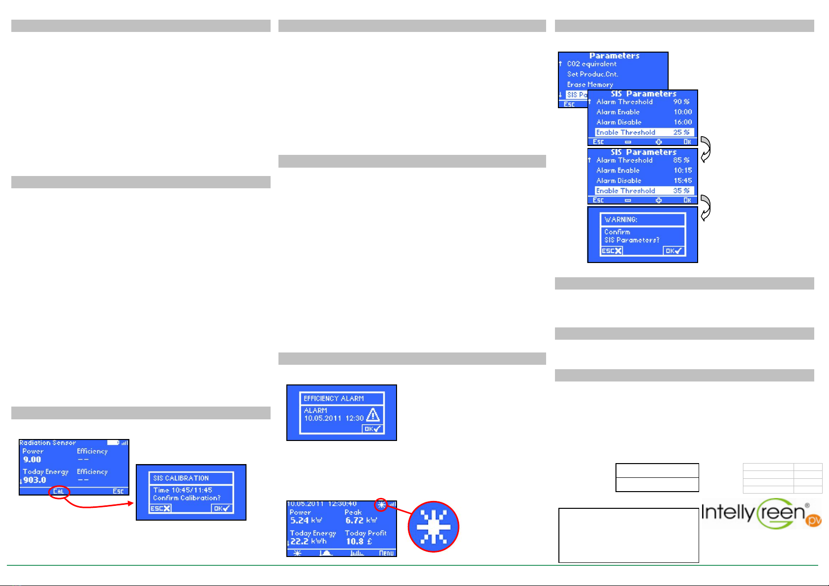
The parameters that regulate the activation and deactivation of the Efficiency Alarm can be
modified from the SIS Parameters Menu (Menu/Parameters Management/SIS Parameter)
When the Efficiency Alarm is activated, the In-house Display shows a warning window.
Together with the display of the window, the buzzer sounds intermittently.
The date/time displayed indicates the starting time of the alarm condition.
The alarm messages stay even after the alarm is off. In that case, the displayed message alerts that
an alarm was on, but now it's off.
Pressing the "Menu" button (fourth button from the left) during the alarm warning stops the warning
and displays the main screen again (also turning off the buzzer). In that case, if the alarm is still
active, you'll only see a flashing sun next to the icon indicating the radio signal to show the situation
is ongoing.
The calibration process is executed pressing the button under "Cal" (second button from the left)
inside one of the SIS sensor's information screens.
If the calibration is performed an hour and a half before turning on the In-house Display or if the
data from one of the two sensors is absent, the message "No Data" is displayed. Similarly, if the
data collected in the last hour of operation is incorrect, a notification is displayed.
SIS Sensor Installation
SIS sensor calibration
Activation of the SIS sensor's calibration process
Calculation of the System Efficiency
Efficiency Alarm
Efficiency Alarm Warning
SIS Parameters
Standards
Disposal
Warranty Conditions
TYPE OF MODULE
SERIAL NUMBER
Installer’s stamp
4-noks s.r.l.
Via per Sacile, 158
31018 Francenigo di Gaiarine (TV) ITALY
Tel. (+39) 0434.768462 Fax. (+39) 0438.694617
www.4-noks.com e-mail: info@4-noks.com
INSTRUCTIONS
INPV
SERIES
001
VERSION
1.3
Date
05/2011
4-noks s.r.l. - Francenigo of Gaiarine (TV) - Italy
Pressing the keys “↓” / “↑” the
parameters scroll.
Pressing the button under "-" and
the button under "+" (second and
third button from the left)
decreases and increases the
selected value.
If you change one or more values,
pressing the "Menu" button will
prompt you to confirm the
programming. Pressing the
"Menu" button again will save your
changes.


