Inter-Track IT-B240 User manual
IT-B240 INTER-TRACK
Luxury Magnetic
Exercise Bike

To ensure your safe, reliable and comfortable use of this exercise
bike, please read the following important matters and all operation
instructions before use.
1.
This fitness bike is a fixed fitness equipment and is an aerobic training equipment for improving
cardiovascular function.
2.
The exercise bike should be placed on the flat ground when in use.
3.
Before use, please check that all bolts, andother parts are properly installed andlocked.
4.
Please wear appropriate clothes, shoes and socks, please do not wear a dress or too long blouse, so
as that itdoesn't hook on the exercise bike.
5.
The activity space of this machine should be larger than 120*100*200 cm.
6.
Children should be supervised to ensure that they do not play with utensils.
7.
This appliance is not intended for use by persons (including children) who are physically weak, slow in
response or have mental disorders, unless it is safely used under the guidance or with the help of a
person responsible for their safety.
8.
The maximum weight of the user of the machine shall not exceed 130Kg.
9.
The braking device of the machine is magnetic resistance type.
10.
The machine meets the requirements of EN957-5HC class.
Warning: Violation of the above safety regulations will result in personal and equipment injuries.

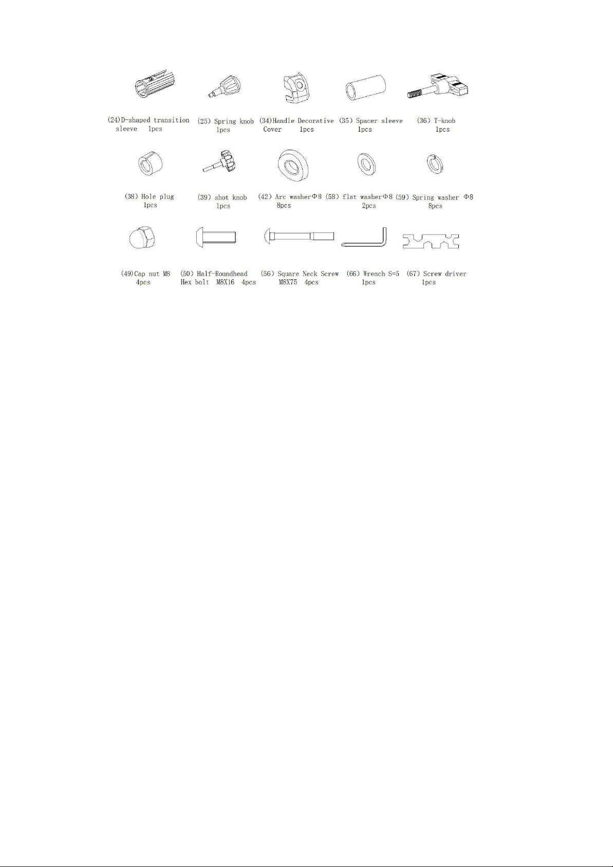
Tools and accessories
(24) D-shaped transition 1pc
(25) Spring knob 1pc
(34) Handle Decorative 1pc
(35) Spacer sleeve 1pc
(36) T-knob 1pc
(38) Hole plug 1pc
(39) Shot knob 1pc
(42) Аrс wаѕhеrФ8 8pcs
(58) Flаt wаѕhеrФ8 2pcs
(59) Ѕрrіng wаѕhеr Ф8 8pcs
(49) Cap nut M8 4pcs
(50) Half-Roundhead Hex bolt M8X16 4pcs
(56) Square Neck Screw M8X75 4pcs
(66) Wrench S=5 1pc
(67) Screw driver 1pc

Part list
NO.
Description
Qty
NO.
Description
Qty
1
Rear foot tube
1
35
Spacer sleeve
1
2
Front foot-cover
2
36
T-knob
1
3
Rear foot cover
2
37
Crank Decorative Cover
2
4
Main frame
1
38
Hole plug
2
5
Front foot tube
1
39
Shot knob
2
6
Back foot tube
1
40
Seat cushion adjustable bracket
1
7
Handlebar support
1
41
Square cap
2
8
Hand bar
1
42
ARC w asher
8
9
Ф25 Ball plug
2
43
Pull Rod
2
10
Handrail bushing
2
44
Adjusting yoke
2
11
Meter
1
45
Adjust slice
2
12
Pulse sensor
2
46
Flat Washer Ф6
3
13
Front plastic cover
1
47
Spring w asher Ф6
2
14
Seat cushion tube cover
1
48
Lock Nut M6
2
15
Seat bracket
1
49
Lock Nut M8
4
16
Meter w ire lower
1
50
Half-Roundhead Hex bolt M8X16
4
17
Meter w ire upper
1
51
Half-Roundhead Hex bolt M8X20
1
18
Heart rate w ire
1
52
Cross Recessed Pan Head screw M5X35
1
19
Seat cushion
1
53
Cross head Pan Head Tapping screw ST4X8
2
20
Right cover
1
54
Cross head Pan Head Tapping screw ST4.2X16
8
21
Left cover
1
55
Cross head Pan Head Tapping screw ST4.2X20
2
22
Crank
1
56
Square Neck Screw M8X75
4
23
Belt w heel
1
57
Lock Nut
2
24
D-shaped transition sleeve
1
58
Flat Washer Ф8
3
25
Spring knob
1
59
Spring w asher Ф8
11
26
Bearing set
1
60
Flat Washer Ф5
1
27
Pressing w heel bracket
1
61
Lock Nut M8
6
28
Pressing belt w heel
1
62
Lock Nut M10
2
29
4V Belt
1
63
Half-Roundhead hex bolt M6X12
1
30
Fly wheel
1
64
Cross Recessed Pan Head Screw M5X12
4
31
8-section tension control
1
65
Pedal Belt
2
32
Resistance cable
1
66
Wrench S=5
1
33
Pedal(Left & Right)
2
67
Screw driver
1
34
Handle Decorative Cover
1

23 Belt w heel
1
57 Lock Nut
2
24 D-shaped transition sleeve
1
58 Flat Washer Ф8
3
25 Spring knob
1
59 Spring w asher Ф8 11
26 Bearing set
1
60 Flat Washer Ф5
1
27 Pressing w heel bracket
1
61 Lock Nut M8
6
28 Pressing belt w heel
1
62 Lock Nut M10
2
29 4V Belt
1
63 Half-Roundhead hex bolt M6X12
1
30 Fly wheel
1
64 Cross Recessed Pan Head Screw M5X12
4
31 8-section tension control
1
65 Pedal Belt
2
32 Resistance cable
1
66 Wrench S=5
1
33 Pedal(Left & Right)
2
67 Screw driver
1
34 Handle Decorative Cover
1
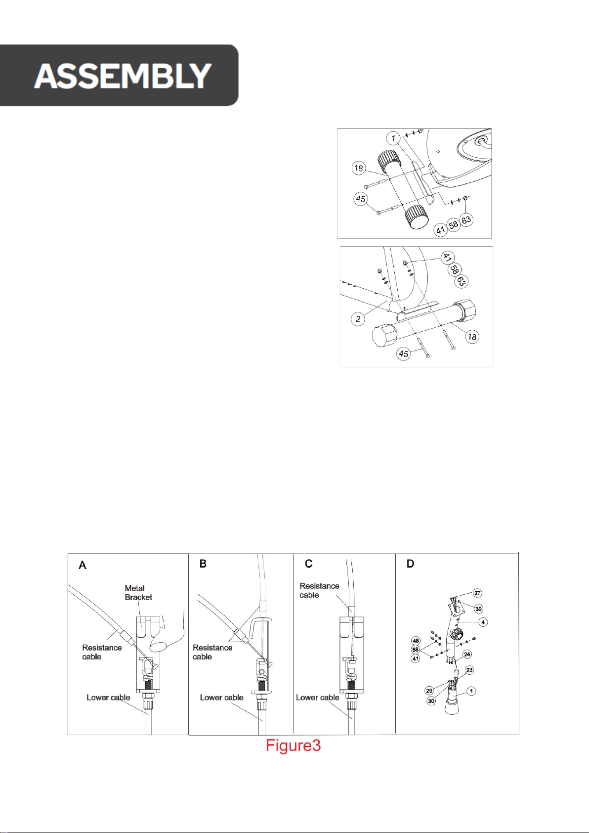
All pipe plugs have been installed.
1. With 2 sets Square Neck Screw(No. 56), Arc
Washer (No.42), Spring washer (No. 59) & Lock
Nut (No.49) attach front foot tube (No. 5) on main
Frame (No.4).
2. With 2sets Square Neck Screw(No. 56), Arc
Washer (No.42), Spring washer (No.59) &Lock Nut
(No.49) attach Rear foot tube(No. 1 )on Main
frame (No.4).
3. A. Connect the Meter wire (No.16&.17) of the upper and lower sections of the electronic table connection, and then
connect the terminal of the lower end of the 8-section spinner body (No.31) firmly with the resistance cable
(No.32).
(Note: first of all the output adjustment knob to the "+" direction to the end (at this time the output of the spinner
terminal extension to the longest), according to the figure of the joint terminal sleeve in the output adjustment wire
connection hook, pull up the output adjustment of the upper end stuck into the box slot. If the upper end of the
output fine adjustment body line cannot just be stuck into the adjustment box slot, please turn the lower end of the
adjustment box nut to the appropriate position, so that the output fine adjustment body line at the top of the clip
just stuck into the adjustment box slot. (See Figure 3-A, B and C)
B: Hand over Handlebar support (No.7) set into the Main frame (No.4) to take over by 4 sets of Half-Roundhead Hex
Bolt (No.50), Spring washer(No.59) and ARC washer (No.42) will hand over Handlebar support (No.7) connected to
the frame (No.4) tighten. (See Figure3-D)

4. A. Insert the heart Pulsesensor (No.12) through the side hole on
the Handlebar support (No.7) and through the upper end; Then cover
the heart rate line (No. 18) with the threading hole plug (No.38), plug
the hole on the Handlebar support (No.7), and then cover the hand
handle bar (No.8) in the clamping tube hoop on the Handlebar
support (No.7), as shown in the figure, then cover the handle decorative
cover (No.34) and the spacer sleeve (No.35), and lock itwith the T-knob
(No.36).
B. Connect the electronic meter (No.11) and heart rate wire (No.16) to the
corresponding connector of the electronic meter, and then put the extra wire
plug into the Handlebar support (No.7); Then the convexity of the electronic
watch is set to the welding seam of the forehand connector, the upper end of
the electronic watch is fixed to the Handlebar support (No.7), and is fixed with
the Cross Recessed Pan Head Screw (No.64).
Note: the clamping teeth on the hand bar (No.8) must be consistent with
the clamping groove of the tube hoop of the Handlebar support (No.7).
5. With 3 sets of Locknut (No.61), Spring Washer (No.59) & flat washer
(No.58) install the seat cushion (No.19) on the seat cushion adjustable
bracket (No.40).
6. A.Then insert the seat bracket (No.15) into the D-shaped transition sleeve (1No.24),
insert the seat bracket (No.15) into the seat support pipe of the Main frame (No.4),
and align the upper end rotary hand seat hole of the seat support pipe of the Main
frame (No.4) with a certain hole on the seat bracket (No. 15); Then insert the Spring knob (No.25) into the hole and
tighten. (See Figure 6)
B.Put seat cushion adjustable bracket (No. 40) on the upper end of the seat bracket
(No.15) according to the direction Shown in the figure.After adjusting a certain position,
tighten the seat cushion with shot knob (No.39).
REMARK:
1. To adjust the position of the Seat bracket (No.15), the Spring knob (No.25) should
be unscrewed. After adjusting the Seat bracket (No.15) to the appropriate position,
then tighten the spring knob (No.25).
2. To adjust the positions of the seat cushion (No. 19), just unscrew the seat
cushion to adjust the shot knob (No.39). After adjusting the Seat bracket (No.15) to
the appropriate position, tighten the shot knob (No.39)
3. lf the cushion is found to be skewed, loosen the fixing nut at the lower end of the
cushion, adjust the cushion to the correct position, and then lock it tightly.
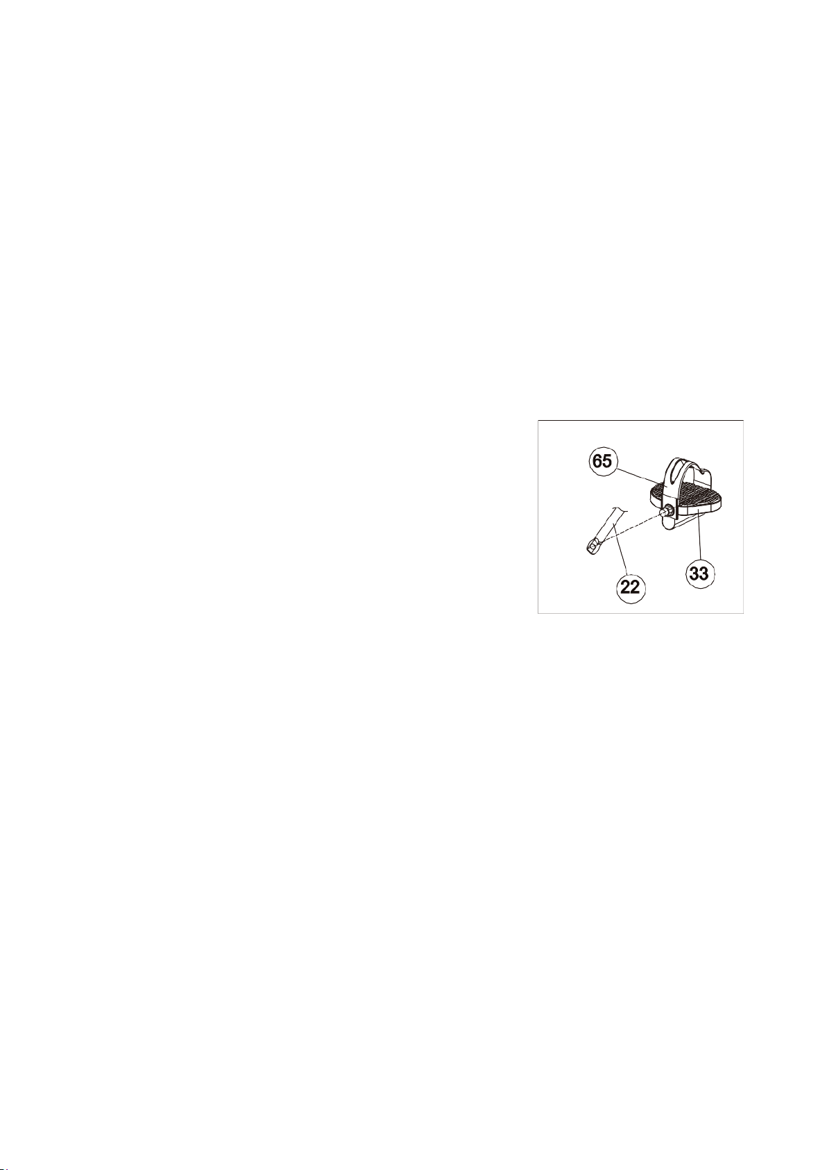
7.Fasten the Belt (No. 65) on the Pedal (No.33) first,
then mount them on the crank (No.22). (see figure 8)
Note: left (L), right (R) are indicated on the foot pedal
shaft.
When stamping quickly in one direction, do not
immediately kick in the other to avoid injury.

1.
Load adjustment: resistance fine tuning knob, clockwise rotation, resistance increase, according to your own
needs to adjust the level of resistance.
2.
Adjusting the height of the seat: loosen and pull back the hand screw on the seat cushion cannula, lift or lower the seat
cushion tube to an appropriate position according to the needs of the wearer. Then, the hand screw will be
automatically inserted into the seat cushion tube hole to tighten the hand screw.
3.
When riding a bike, sit on the cushion, fasten the pedal strap and hold the handle with both hands. The upper body can
freely change its position
FUNCTION KEYS/MANUAL MODE:
1. MODE: Push down for selecting functions. If the MODE button is held down for a long time, all
values will return to 0 except the ODO.
2. SET: To set the values of time, distance,pulse and calories when not in scan mode.
3. RESET: Push down for resetting time, distance & calories, the current data change to 0.
WINDOW DISPLAY
•TIME: Displays the elapsed using time (0:00-99:59 MIN).
•SPEED: The speed range is 0.0-999.9KM/H (or Mile/H).
•DISTANCE: Displays the total distance traveled (0.0-9999KM or MILES).
•CALORIES: Displays total calories burned (0.0-9999 CAL).
•PULSE (if have): Displays your pulse data when hands are placed on the sensors (40-240BPM).
I. Installation method
1.
Remove the battery door on the back shell of the meter and install two new 1.5V AA batteries in the
positive and negative directions of the battery box (for battery products not installed).
2.
Fix the instrument on the pipe in front of the fitness equipment with screws.
3.
Connect the sensor wire plug with the outlet connector on the back of the instrument or insert the
signal input jack on the back of the instrument.
4.
Quick step on the fitness equipment and the displayed speed changes indicate that the installation
is qualified; otherwise, check whether the magnet seat and the sensor are installed correctly and
whether the sensor wire plug and the lead wire of the watch head are connected reliably.

II: Method of use:
1.
Press the MODE key to select the display window that needs to be SET or cleared, and the "SET"
symbol on the corresponding window flashes. Press the SET key to SET the time, distance or
calories required. Press the RESET key to clear the corresponding window display value.
2.
Step on the fitness equipment to start measuring, and observe your exercise parameters
according to the contents displayed in the window.
3.
Heart rate measurement: press any key, then grasp the corresponding position of heart rate
sensor metal plate with the left and right palms respectively (note: each palm should touch
two metal plates at the same time). The monitor in the heart rate display window will show
your current heart rate in seconds or less. When the heartbeat signal is received during the
measurement, the heartbeat corresponds to the "❤". In order to prevent the influence of
palm movements on heart rate measurement and ensure the accuracy of heart rate
measurement, it is suggested that the heart rate measurement should be carried out after
the exercise is suspended or stopped, and the heart rate measurement should not be carried
out at the same time of running.
Hint: Sometimes there will be signal interference when the palm holds the metal sheet. The
heart rate displayed in the first 2~3 seconds may not be correct and appear high, which is a
normal phenomenon. Then the heart rate will return to normal measurement. This method
of heart rate detection is mainly helpful to determine the amount of exercise you do, not as
a basis for disease treatment.
III:The battery replacement
When the display darkens or shows no display, remove the battery cover and install two new
1.5V AA batteries in the positive and negative direction of the battery. Install the battery cover.

(1) Maintenance
1.
Regularly check whether the bolts and nuts of each part are fastened, whether the adjusting
knob is locked, whether the rotating part is flexible, and whether there are any worn or damaged
parts. Ensure that all parts are in good condition to ensure the safety of the equipment.
2.
Parts that are worn or damaged should be replaced immediately or sent to the maintenance
center for replacement before use after repair.
3.
Keep the equipment clean, but do not wipe it with acid, alkaline or organic solution.

Malfunction
Reason
Treatment
Base is unstable.
Floor is not flat or there is
small object under the front
or rear stabilizer.
The rear base feet have not been
leveled when assembling.
Remove the object.
Re-level the base
Adjust the rear base feet.
Handlebar or seat
cushion is shaking.
The screws and round knob are
loose.
Tighten the screws and round
knob.
Loud noise from the
moving parts.
The interval of the parts is improper
tighten. Open the covers to adjust.
No resistance when
riding the upright bike.
The interval of the magnetic
resistance increases.
Tension control is damaged.
Running belt is slippery.
Bearing is damaged.
Open the covers to adjust.
Change the tension control.
Open the covers to adjust.
If you couldn't solve any of the following problems,
you can contact us on "Intertrack.net"

•
Resistance Type: Magnetic resistance.
•
Max User Weight: 130kg.
•
Flywheel: 4kg.
•
Driving Mechanism: Belt Driven.
•
Seat Adjustment: Horizontal and vertical.
•
Display: LCD display.
•
Display features: Speed, Time, Distance, Calories burnt, and Heartrate.
•
Assembly size: 93*54.5*128.5cm.
•
Resistance levels: 8 levels.
•
Gross Weight/Net Weight: 24.5kg/21.5kg.
SPECIFICATIONS
Table of contents
Other Inter-Track Exercise Bike manuals


