Inter-Track IT-E240 User manual

IT-E240 INTER-TRACK
Luxury Magnetic
Elliptical Machine

To ensure your safe, reliable and comfortable use of this exercise
bike, please read the following important matters and all operation
instructions before use.
1.
This fitness bike is a fixed fitness equipment and is an aerobic training equipment for improving
cardiovascular function.
2.
The exercise bike should be placed on the flat ground when in use.
3.
Before use, please check that all bolts, and other parts are properly installed andlocked.
4.
Please wear appropriate clothes, shoes and socks, please do not wear a dress or too long blouse, so
as that is doesn't hook on the exercise bike.
5.
The activity space of this machine should be larger than 120*100*200cm.
6.
Children should be supervised to ensure that they do not play with utensils.
7.
This appliance is not intended for use by persons (including children) who are physically weak, slow in
response or have mental disorders, unless it is safely used under the guidance or with the help of a
person responsible for their safety.
8.
The maximum weight of the user of the machine shall not exceed 130Kg.
9.
The braking device of the machine is magnetic resistance type.
10.
The machine meets the requirements of EN957-5HC class.
Warning: Violation of the above safety regulations will result in personal and equipment injuries.


Tools and accessories
(53)D-washer
2pcs
(43)Wave Washer
4pcs
(59)Hexagon head bolt
M8*20 2pcs
(13)Nut capS=17
8pcs
(20)Nut capS=13
2pcs
(16)Arc Spacer
2pcs
(21)Nut cap S=19
2pcs
(61)Hexagon head bolt
M8*45 4pcs
(67)
Locknut M8
4pcs
(66)
Locknut M10
4pcs
((71)flat washerΦ10
6pcs
(88)D-shaped transition
sleeve 1pcs
(86)Spring knob
1pcs
(87)shot knob
1pcs
(78)Wrench S=5
1pcs
(79)Wrench S=8
1pcs
(80)Screw driver
1pcs
(65)Cap nut M8
8pcs
(54)Square Neck Screw
M8X75 4pcs
(55)Square Neck Screw
M8X45 4pcs
(56)Half-Roundhead
Hex bolt M8X20 8pcs
(77)Spring washer Φ12
2pcs
(75)Spring washer Φ8
12pcs
(76)Spring washer Φ10
6pcs
(52)Arc washerΦ8
12pcs
(71)flat washerΦ8
4pcs
(72)Large flat
washerΦ8 2pcs

Part list
serial
number
NAME QTY
serial
number
NAME QTY
1
Frame weldment
1
48
F33.4 square plug
2
2 Front bracket weldment 1 49 Off-center foot cover 2
3
Left swing arm weldment
1
50
Left pedal shaft 1/2
'
1
4 Right swing arm weldment 1 51 Right pedal shaft 1/2'1
5 Hand held heart rate weldment 1 52 Arc washer Ф8 12
6
Roller frame weldment
1
53
D-shaped washer
2
7 Welded parts of rear clamp seat 2 54
Semi-round head square neck bolt
M10×75
4
8
U-shaped seat weldment
2
55
Semi-round head square neck bolt M8×45
4
9 Foot tube 2 56 Hexagonal bolt cup head M8×16 9
10
Rotatable foot cover
2
57
Hexagonal bolt cup head M10×55
2
11 Pedal tube 2 58 Hexagonal bolt cup head M6×10 1
12 Footboard 2 59 Hexagonal-head bolt M8×20 2
13
Nut cap S=17
8
60
Hexagonal-head bolt M10×70
2
14 Left hand handle tube 1 61 Hexagonal-head bolt M8×45 4
15
Right hand handle tube
1
62
Pan head screws with cross recess M5X35
1
16 Arc spacer 2 63
Cross recessed pan head tapping screws
ST4X20
11
17 Electronic watch 1 64
Cross recessed pan head tapping screws
ST4X10
2
18
Power output fine tuning
connection
1 65 Cap nut M8 8
19 Eight-section trimmer body 1 66 Locknut M10 6
20
Nut cap S=13
2
67
Locknut M8
5
21 Nut cap S=19 2 68 Hexagonal nutM6 2
22
Swing arm sleeve
4
69
Hexagon nuts with flange M10
2
23
Axle sleeve
8
70
Flat washer Ф10
8
24 Internal magnetic flywheel 1 71 Flat washer Ф8 4
25
Hold-on handle sleeve of heart rate
tube in hand
2 72 Large washer Ф8 2
26 Nylon washer 4 73 Arc washer Ф5 1
27
Heart rate sensor
2
74
Spring washer Ф6
1
28 Large end plug of Ф29 pipe 2 75 Spring washer Ф8 12
29 F30 square plug 2 76 Spring washer Ф10 6
30
Left lock nut 1/2
'
1
77
Spring washer Ф12
2
31 Right lock nut 1/2'1 78 Dual-purpose screwdriver s=5 1
32
Crank spacer
2
79
Hex wrench s=8
1
33 Nine bowls 1 80 Multi-mouth wrench 2
34 Pinch roller 1 81
35
A section of crank
1
82
Seat cushion bracket weldment 1
36 6V belt 1 83
Welding part of seat cushion adjusting
frame 1
37
Large pulley
1
84
Seat cushion tube decorative cover 1
38 Right shield 1 85
Seating washer 1
39 Left shield 1 86
Stretching rotating handle 1
40
Heart rate line
2
87
Torx handwheel 1
41 Sensing line 1 1 88
D-shape hollow plug 1
42
Sensing line 2
1
89
Great round end plug 2
43 Wave elastic washer 4
Pan head screws with cross recess M5X12 4
44
Adjusting pull rod
1
45
Adjusting pull gear
2
46 Adjusting drawing 2
47
Handle sleeve of handle pipe
2

Note:
(1) Please refer to the schematic diagram and install it step by step.
(2) All plugs, foot pads and shields have been installed before leaving the factory. The swing arm, U-shaped clamp,
pedal tube and rear clamp seat have been assembled to form a swing rod assembly.
(3) When connecting parts with bolts and nuts, assemble them directly by hand. After all parts are assembled, use tools
to tighten them in place one by one when making final adjustment.
(4) Open the packing box, take out the parts and put them in different categories, and carry out the following
installation with reference to the installation diagram and parts list.
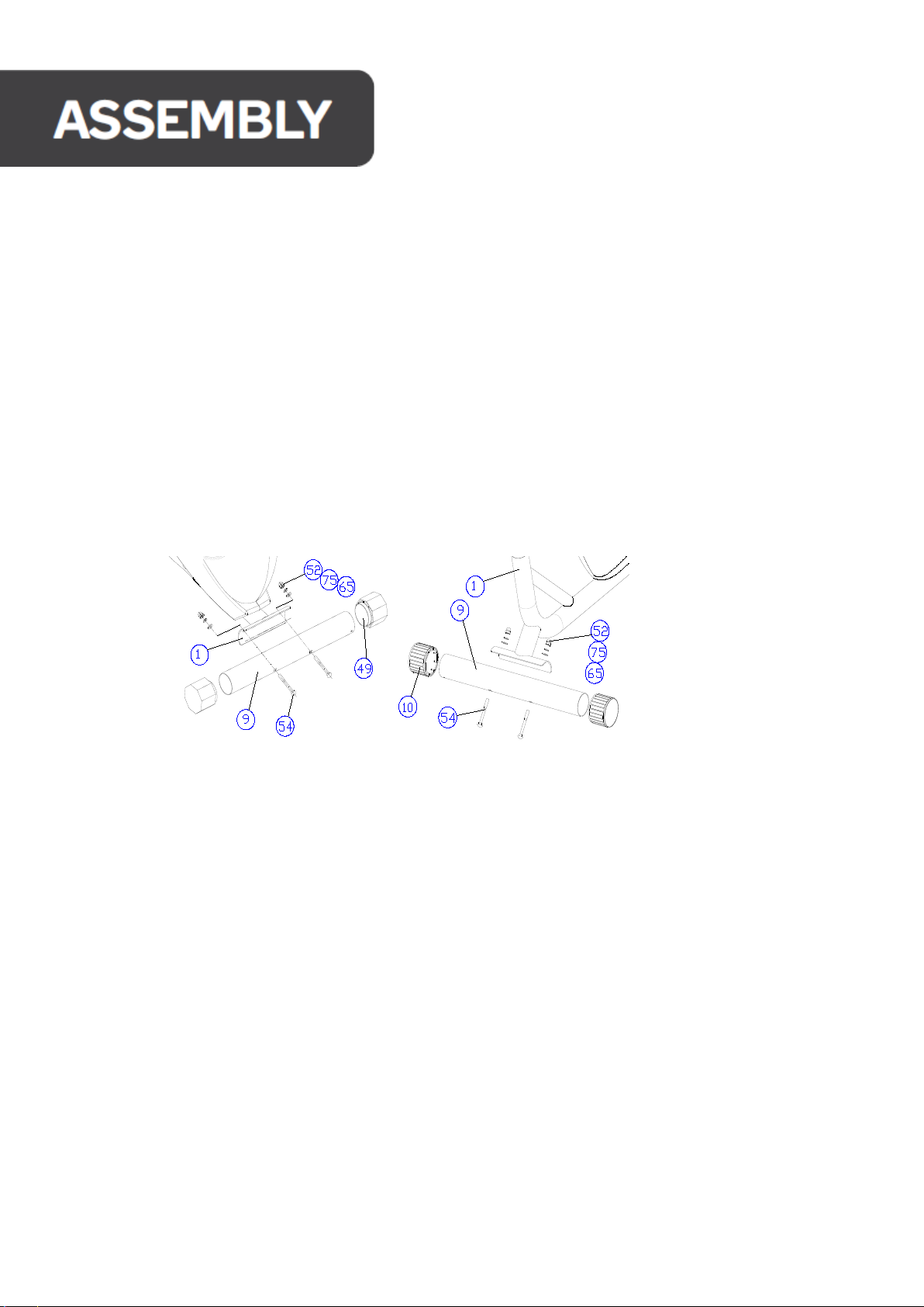
1. Install the rear bottom pipe
Install the rear bottom pipe (2) on the rear connecting plate of the frame (1) with two sets of semicircular head square
neck bolts M8×75(54), arc washer ф 8 (52), spring washer ф 8 (75) and cap nut M10(65). (see fig.1)
2. Install the front bottom pipe
Use two sets of semicircular head square neck bolts M8×75(54), arc washer ф 8 (52), spring washer ф 8 (75) and cap nut
M8(65) to install the
front foot pipe (2) on the front connecting plate of the frame (1). (see fig.2)
Figure 1 Figure 2
3.Installing front bracket
A. Connect the terminal at the lower end of the eight-section trimmer body (19) firmly with the output fine
adjustment connecting line (18). (Note: firstly, turn the output trimmer knob all the way to the "-"direction (at this
time, the connector terminal of the output trimmer body extends to the longest), tighten the connector terminal
on the connecting hook of the output trimmer connecting wire connector as shown in the figure, and pull it up hard
to clamp the upper end of the output trimmer body into the groove of the adjusting frame. In case that the upper
end of the output fine adjustment body line cannot be just clamped into the groove of the adjusting frame, please
screw the nut at the lower end of the adjusting frame to a proper position, so that the upper end of the output fine
adjustment body line is just clamped into the groove of the adjusting frame. (see fig. 4-A, b and c)
B. Connect the sensor line 2(41) joint at the lower end of the front bracket (2) and the sensor line 1(42) joint at the
upper end of the frame (1) firmly. (see fig.3-D)
C. Set the front bracket (2) on the frame (1) and lock it with 6 sets of hexagon socket head bolts M8×16(56), spring
washers ф 8 (75) and arc washers ф 8 (52). (see fig.3-D)

Figure 3
4.Install the hand-held heartrate tube
Pass the heart rate wire (40) through the small hole on the back of the upper end of the front bracket (2), and then
pass out from the upper port,Then align the hand-held heart rate tube weldment (5) with the screw hole on the front
bracket (2), and lock it with two sets of hexagon socket head bolts M8×20(56), spring washers ф 8 (75) and arc
washers ф 8 (52). (see fig.4)
5.Installing electronic watch
A. Connect the heart rate line (40) and the sensing line 2(41) with the corresponding connectors of the electronic watch
(17) and insert the redundant lines into the tube.
B. Align the hole position of the electronic watch (17) with the hole on the instrument panel on the front bracket (2).
And locked with four corner bolts M5×12(90). (see fig.5)
Figure 4Figure 5
6.Install the left and right swing arm assemblies
Two arc spacers (16) are respectively sleeved on both ends of the swing rod shaft on the front bracket (the arc
mouth is inward), then a wave elastic washer (43) is sleeved on the swing rod shaft on the front bracket (one end of
the long sleeve is inward). Put on plastic flat washer ф 8 (53), large flat pad ф 8 (72), spring washer ф 8 (75), lock
hexagon bolt M8×20(59), and then fasten nut cap (20),At this time, the swing rod should be able to swing freely.
(see fig.6)
Figure 6
Metal
Bracket
R esistan ce
c a b le
Lo w er
c a b le
R esistan ce
c a b le
Lo w er
c a b le Lo w er
c a b le
R esistan ce
c a b le

7
.
Pedal shaft installation (same left and right)
the pedal pipe rear clamp weldment (35), and then put on the wave elastic washer Pass the pedal shaft (30) through
(28) and pedal shaft spacer (54) in turn, then screw the pedal shaft (30) onto a crank (67), tighten the pedal shaft with a
booster rod and lock it with a lock nut (as
shown in fig.7)
Figure 7Figure 8
Note: The left and right threads must be installed in a matching way, and there are left and right marks on the
corresponding spare parts: left thread "L" and right thread "R".
8. Install foot pedals
Align the pedals (5) (one on the left and one on the right) back and forth, and fix them on the pedal tube (4) with four
sets of hexagon-head bolts M8×50(37), flat washers ф 8 (50) and locknuts M8(42). (see fig.8)
9.Left and right hand handle
Use four sets of hexagon-head bolts M8×45(55), arc washers ф 8 (52), spring washers ф 8 (75) and cap nuts M8(65) to
connect the two handle tubes (14, 15) to the upper ends of the left and right swing arms (3). (see fig.9)
Note: Hexagon head bolts must be inserted into hexagonal holes of swing arms.
10.Install the nut cover
After the whole machine is installed and adjusted, the nut cap (13) is clamped at the joints of the U-shaped seat
weldment (8), the swing arm (3) and the pedal tube (11). (see fig.10)
Figure 9 Figure 10
11.Seat cushion installation
Install the seat cushion (85)onthe seat cushion adjusting frame (83)with three sets of
nylon nuts M8(67), spring washers ф 8 (75)andflat washers ф 8 (71). (see fig.11)
Figure 11

12.Seat cushion frame installation
A.Then insert the lifting cushion frame weldment (82) into the D-shaped transition
sleeve (88), and insert the lifting cushion frame weldment (82)into the seat branch
pipe of the main frame (1), sothat the upper end screw seat hole of the seat branch
pipe of the main frame (1) is aligned with a certain hole position on the lifting cushion
frame weldment (82); Then insert the stretching knob (86)into the hole, and tighten
the handwheel with force. (see fig.12)
Figure 12
B. insert the seat cushion adjusting frame (83) into the upper end of the lifting seat cushion frame weldment
(87) after
(82) according to the direction shown inthe figure, and lock itwith a plum blossom handwheel
adjusting a certain position. (see fig.12)
Remarks:
1. When lifting the seat cushion frame weldment (82)at high and low positions, just unscrew the stretching
knob (86), and then tighten the hand wheel with force after lifting the seat cushion frame weldment (82) to a
suitable position.
2. When adjusting the front and rear position ofthe seat cushion frame (83), just screw out the plum hand
wheel (87), adjust the seat cushion frame (83)to a proper position, and then tighten the hand wheel hard.
3. If the seat cushion isfound to be skewed, loosen the fixing nut at the lower end ofthe seat cushion, adjust
the seat cushion and lock it again.

1.
Load adjustment: resistance fine tuning knob, clockwise rotation, resistance increase, according to your own
needs to adjust the level of resistance.
2.
Adjusting the height of the seat: loosen and pull back the hand screw on the seat cushion cannula, lift or lower the seat
cushion tube to an appropriate position according to the needs of the wearer. Then, the hand screw will be
automatically inserted into the seat cushion tube hole to tighten the hand screw.
3.
When riding a bike, sit on the cushion, fasten the pedal strap and hold the handle with both hands. The upper body can
freely change its position
FUNCTION KEYS/MANUAL MODE:
1. MODE: Push down for selecting functions. If the MODE button is held down for a long time, all
values will return to 0 except the ODO.
2. SET: To set the values of time, distance,pulse and calories when not in scan mode.
3. RESET: Push down for resetting time, distance & calories, the current data change to 0.
WINDOW DISPLAY
•TIME: Displays the elapsed using time (0:00-99:59 MIN).
•SPEED: The speed range is 0.0-999.9KM/H (or Mile/H).
•DISTANCE: Displays the total distance traveled (0.0-9999KM or MILES).
•CALORIES: Displays total calories burned (0.0-9999 CAL).
•PULSE (if have): Displays your pulse data when hands are placed on the sensors (40-240BPM).
I. Installation method
1.
Remove the battery door on the back shell of the meter and install two new 1.5V AA batteries in the
positive and negative directions of the battery box (for battery products not installed).
2.
Fix the instrument on the pipe in front of the fitness equipment with screws.
3.
Connect the sensor wire plug with the outlet connector on the back of the instrument or insert the
signal input jack on the back of the instrument.
4.
Quick step on the fitness equipment and the displayed speed changes indicate that the installation
is qualified; otherwise, check whether the magnet seat and the sensor are installed correctly and
whether the sensor wire plug and the lead wire of the watch head are connected reliably.

II: Method of use:
Hint: Sometimes there will be signal interference when the palm holds the metal sheet. The
heart rate displayed in the first 2~3 seconds may not be correct and appear high, which is a
normal phenomenon. Then the heart rate will return to normal measurement. This method
of heart rate detection is mainly helpful to determine the amount of exercise you do, not as
a basis for disease treatment.
III:The battery replacement
When the display darkens or shows no display, remove the battery cover and install two new
1.5V AA batteries in the positive and negative direction of the battery. Install the battery cover.
1.
Press the MODE key to select the display window that needs to be SET or cleared, and the "SET"
symbol on the corresponding window flashes. Press the SET key to SET the time, distance or
calories required. Press the RESET key to clear the corresponding window display value.
2.
Step on the fitness equipment to start measuring, and observe your exercise parameters
according to the contents displayed in the window.
3.
Heart rate measurement: press any key, then grasp the corresponding position of heart rate
sensor metal plate with the left and right palms respectively (note: each palm should touch
two metal plates at the same time). The monitor in the heart rate display window will show
your current heart rate in seconds or less. When the heartbeat signal is received during the
measurement, the heartbeat corresponds to the "❤". In order to prevent the influence of
palm movements on heart rate measurement and ensure the accuracy of heart rate
measurement, it is suggested that the heart rate measurement should be carried out after
the exercise is suspended or stopped, and the heart rate measurement should not be carried
out at the same time of running.

(1) Maintenance
1.
Regularly check whether the bolts and nuts of each part are fastened, whether the adjusting
knob is locked, whether the rotating part is flexible, and whether there are any worn or damaged
parts. Ensure that all parts are in good condition to ensure the safety of the equipment.
2.
Parts that are worn or damaged should be replaced immediately or sent to the maintenance
center for replacement before use after repair.
3.
Keep the equipment clean, but do not wipe it with acid, alkaline or organic solution.

If you couldn't solve any of the following problems,
you can contact "Intertrack.net"
Causal
barrier Original cause Exclusion method
Uneven
frame
1. uneven ground or sundries
2. The base is not leveled
when the frame is assembled
1. Eliminate sundries
2. Loosen the frame connecting
bolts, level the base, and then
tighten the bolts
3. Adjust the eccentric foot
sleeve of the rear bottom pipe
Unstable
handle Loose threads Tighten bolts
Rotating
parts have
abnormal
noise
Gap imbalance Open the shield adjustment
Rotational
weakness
1. the magneto resistance
gap increases
2. The trimmer is damaged
3. The belt slips
1. Open the guard to adjust
2. Replace
3. Open the guard to adjust

•
Resistance Type: Magnetic resistance.
•
Max User Weight: 130kg.
•
Flywheel: 4kg.
•
Driving Mechanism: Belt Driven.
•
Seat Adjustment: Horizontal and vertical.
•
Display: LCD display.
•
Display features: Speed, Time, Distance, Calories burnt, and Heart rate.
•
Assembly size: 130*60*157.5 cm.
•
Resistance levels: 8 levels.
•
Gross Weight/Net Weight: 37kg/33kg.
SPECIFICATIONS
Table of contents
Other Inter-Track Exercise Bike manuals
Popular Exercise Bike manuals by other brands

Retul
Retul Müve SL Build instructions

kinetic
kinetic ROCK AND ROLL T-016 Assembly manual

Domyos
Domyos VM 770 operating instructions

alza ergo
alza ergo APW-EGABW2OFC Installation guide & user manual

Stamina
Stamina Elite TOTAL BODY owner's manual

PLENY
PLENY Folding Exercise Bike Assembly & user instructions