Interactive Instruments Jet Stream 500 User manual
INTERACTIVE
INSTRUMENTS
Jet Stream 500
Instruction Manual
Interactive Instruments, Inc.
704 Corporations Park
Scotia, N.Y. 12302

Jet Stream 500 2
Information in this document is subject to change without notice and does not represent a commitment on
the part of Interactive Instruments, Inc. The software described in this document is furnished under license
agreement or non-disclosure agreement. The software may be used or copied only in accordance with the
terms of the agreement. It is against the law to copy the software on any medium except as specifically
allowed in the license or non-disclosure agreement. No part of this manual may be reproduced or
transmitted in any form or by any means, electronic or mechanical, including photocopying and recording,
for any purpose without the express written permission of Interactive Instruments, Inc.
1993 Interactive Instruments, Inc. All rights reserved.
Printed in the United States of America.
Companies, names, and dates used in examples herein are fictitious, unless otherwise noted.
Printed: September 17, 2004

Jet Stream 500 3
Table of Contents
Safety Guide...............................................................................................................................................4
Installation and Setup .................................................................................................................................5
Overview ....................................................................................................................................................7
Guide to the Jet Stream 500 .......................................................................................................................9
Loading a test model:...................................................................................................................9
Before starting a test: ...................................................................................................................9
Starting a test:...............................................................................................................................9
You are now ready to press the Start button: ...............................................................................9
Adjusting the wind speed:............................................................................................................10
Viewing the results: .....................................................................................................................10
Analyzing the test results: ............................................................................................................10
Adjusting the Angle of Attack: ....................................................................................................11
Stopping a test:.............................................................................................................................11
Error Conditions:..........................................................................................................................11
Available Options.......................................................................................................................................12
Jet Stream 500 Specification ......................................................................................................................13
Technical Information ................................................................................................................................14
Control Electronics ......................................................................................................................14
Force Sensors ...............................................................................................................................14
Wind Speed Sensor ......................................................................................................................15
Wind Speed Control.....................................................................................................................16
Fan Motor Control .......................................................................................................................17
Troubleshooting .........................................................................................................................................18
Limited Warranty .......................................................................................................................................19
Glossary......................................................................................................................................................20

Jet Stream 500 4
Safety Guide
•Follow the instructions and be sure to follow all warnings on the equipment and in the
manual for trouble free service.
•Be sure that a supervisor is present whenever the Jet Stream 500 is in operation. It is the
responsibility of the supervisor to read and understand this manual before operating the
equipment.
•This product is supplied with a grounded power cord. Be sure that you use a wall socket
that conforms to this cord. Bypassing the ground for any reason may cause personal injury.
When using an extension cord, be sure the cord is capable of handling the power
requirements of the wind tunnel. The cord should not be any longer than required.
•Everyone within the immediate area of the Jet Stream 500 must wear proper ear
protection before the instrument is started. The wind tunnel is capable of producing sounds
in excess of 100 db which may cause loss of hearing.
•A security key has been supplied that prevents the Jet Stream 500 from operating when the
key is turned off. The supervisor should have possession of the key to prevent unauthorized
use of the product.
•Before starting the Jet Stream 500, be sure that the room is secure of any objects that
may be blown around while the Jet Stream 500 is under operation. This includes papers,
books, and small objects that may become airborne due to the exhaust wind.
•It is the supervisor's responsibility to inspect the Jet Stream 500 to insure it is in proper
working order and that none of the built-in safety features are bypassed before and during
operation.
•Be sure that the pitot tube is not bent or plugged before operating the Jet Stream 500.
If the pitot tube becomes blocked or damaged, the wind speed will not be under the proper
control of the microprocessor and the wind speed may increase until the error condition is
displayed.
•Do not bypass the fan's power cord. Doing so will damage the wind tunnel as the propeller
blade is not designed for full speed operation. Since the speed is controlled by the
microprocessor, the final speed is regulated to prevent full speed operation under normal use.
•Turn off this product when not in use or during a lightning storm. Unplug the wind
tunnel from the wall to avoid damage due to lightning or when left unattended for long
periods of time.
•Do not attempt to service, repair or disassemble this product yourself as removing covers
may expose you to dangerous voltage or other hazards. No user serviceable parts are inside.
Refer all servicing to Interactive Instruments, Inc.
•Do not expose this unit to rain or moisture. The wind tunnel must be used in a protected
building to prevent shock hazards.
•This product is intended for instructional use only.It should not be used for the
development of designs that could potentially injure humans.

Jet Stream 500 5
Installation and Setup
Unpack the wind tunnel from the shipping container. Retain the packing material provided the
unit must be returned to the factory at a later date. Do not ship the unit in anything other than
this container or damage to the tunnel will result.
After unpacking everything, you will find a wind tunnel with the test bed, control panel, 9 pin data
cable, power cord, and manual. If you are missing any of these parts, please contact Interactive
Instruments immediately.
To assemble the wind tunnel, place the tunnel on a flat stable, surface near a wall socket. Place
the tunnel in a location at room temperature (70 - 80 degrees) and preferably out of direct
sunlight. Be sure that the test bed is on the right hand side of the operator so the wind exhausts to
the left. Place the control panel in front of the wind tunnel so it is accessible to the operator. Plug
the 9 pin data cable into the rear of the test bed and also into the rear of the control panel. Secure
both ends with the cable screws supplied.
Plug the power cord into the rear of the control panel, but do not plug the power cord into the wall
socket yet.
Inspect the wind tunnel for shipping damage. If any damage was caused in shipping, please
contact Interactive Instruments immediately. Operating a damaged tunnel may result in additional
damage to the tunnel or personal injury.
Be sure the intake and exhaust ports are free from obstruction. There should be no papers or
shipping material in the test area or around the Jet Stream 500 during operation.
Level the wind tunnel using the 5 adjustable feet to eliminate measurement errors. If the tunnel is
operated on an uneven surface, the lift and drag forces may be inaccurate. If the tunnel is not
stable during operation, vibrations may also affect the results. To level the Jet Stream 500
properly, start by shortening all of the adjustable feet to the shortest position. Then look at the
level above the test area and use this as a guide to make the remaining adjustments. If the bubble
in the level is out of the center circle, adjustments will be necessary. If the bubble is closest to the
motor (large end of the tunnel), lengthen the feet nearest the intake (small end) first. If the bubble
level is closest to the intake, lengthen the feet under the motor. Be sure to adjust them in pairs.
Next, adjust the feet side to side to place the bubble in the center of the level. Once the tunnel is
level, be sure that all of the outside feet are touching the ground. This can be checked by placing
paper under each foot and pulling on it to check the clearance. If a foot is not touching, adjust it
so it is. Once the tunnel is level and stable, adjust the foot in the center of the tunnel base until it
touches the floor. Check to see that the Jet Stream is stable by rocking the tunnel. If it is balanced
properly, the tunnel will not rock.
Verify that the control panel's main power is off before plugging the control panel into a 110 volt,
60 Hz grounded wall outlet. Since the wind tunnel's fan motor may draw as much as 12 amps, be
sure the wiring and circuit protection is rated at 15 amps or more. Do not bypass the ground pin
on the power cord, this is needed for your safety.

Jet Stream 500 6
Activate the wind tunnel by turning the Security key counterclockwise to unlock.
Test the unit by turning the wind speed control dial counterclockwise to 0 and powering up the
unit by toggling the power switch located in the back. As the control panel is powering up, it
should display the following messages on the LCD panel:
Testing System
If the display prompts
*** SYSTEM ERROR ***
This is due to the microcontroller detecting an error in the system. Please refer to the Error
Condition section of this manual for more information.
The control panel will default all values in English units (pounds and miles per hour). Pressing
the STOP button as the unit is powered up will display the units in metric (kilograms, kilometers
per hour).
Be sure that everyone in the immediate area is wearing proper ear protection as the Jet Stream 500
can produce noise levels in excess of 100 db. Continued use without proper ear protection
can cause hearing loss.
If everything is OK, press the start button on the front of the control panel. Slowly turn the speed
control clockwise to start the fan motor. If there are any strange noises, turn off the control panel
and call Interactive Instruments for further instructions.
Please review the remainder of this manual for useful information and testing details.

Jet Stream 500 7
Overview
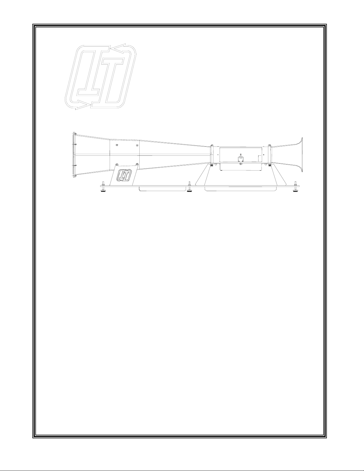
The Jet Stream 500 is a complete wind tunnel package, engineered to study basic aerodynamic
principles of model aircraft wings and CO2cars. The design is optimized to instruct students in
junior high, middle school, high school and university level classes with a focus on ease of use.
Since the wind tunnel is designed as a general instrument, the uses are limitless. From airfoil
research to automobile design, the learning value goes a long way.
Easy to Operate
The tunnel is controlled with an easy to use remote control panel. Starting the tunnel is as easy as
pressing the START button and dialing the desired test velocity. A 20 character by 4 line display
is continuously updated to accurately reflect the system's wind velocity along with the forces
generated on the test model. A one horse power electric motor with a 10" propeller is powerful
enough to produce winds of 80 miles per hour. This is fast enough to test any model.
Instrumentation located in the test area also monitors lift and drag forces exerted on the test model
so forces can be displayed in real time on the display panel. Precision strain gages mounted under
the test bed accurately measure the forces on the model without having to attach them directly to
the model. This allows for easy mounting and unmounting of the test model. The lift over drag
(L/D) ratio is also computed and displayed on the display panel to demonstrate airfoil design
efficiency.
Quality Design
The test area is free of turbulence due to following stringent wind tunnel design rules. By
extending the length of the tunnel and using a special flow straightener, the Jet Stream 500 has
virtually eliminated the test area turbulence that is common in poorly designed tunnels. This
allows the instrumentation to precisely measure the forces within the tunnel to less than 1%.
Wind velocity is constantly monitored hundreds of times a second to maintain a steady flow over
the test model. Using a pitot static tube connected to a differential pressure transducer, the wind
velocity is electronically monitored and controlled. This provides a constant wind speed
independent of the size or angle of the test model. The actual wind velocity is displayed on the
control panel which allows studies to be conducted over a wide range of conditions.

Jet Stream 500 8
Versatile
An easy to access 5.25" x 5.25" x 16" test chamber allows various models to be quickly mounted
for testing. The test bed is easily removed from the tunnel for unrestricted access in mounting and
unmounting models. The test section is made of a clear plastic so the model can be viewed while
under test. An angle of attack adjustment is available to adjust the airfoil +/- 30° with a resolution
of 5° so the model can be tilted without remounting airfoil models. This allows the lift and drag
forces to be measured at various angles and is very useful for demonstrating an airfoil's stall
speed. CO2car designs can also be optimized for speed by measuring the model drag at various
wind velocities. With the drag force measured to .001 lbs., small design changes can be studied.
Self Contained
The tunnel also performs an automatic self test every time the unit is powered up. If an error is
detected within the wind tunnel, the display informs the operator of the error condition and
disables operation. The test also detects calibration and functional problems before allowing the
tunnel to operate. The built-in force gages are automatically zeroed before each test to keep the
display in calibration, therefore the unit should never require recalibration.
Safety
The Jet Stream 500 is designed with safety in mind. The Jet Stream 500 is capable of
automatically shutting down if it detects a problem. A security lock is also added to disable the
unit when a supervisor is not present to prevent unsupervised operation of the wind tunnel.
Overall, the Jet Stream 500 is an invaluable tool when it comes to visually demonstrating
basic to advanced aerodynamic principles to students.

Jet Stream 500 9
Guide to the Jet Stream 500
Loading a test model:
To load a test model, be sure the wind tunnel is stopped by pressing the Stop button and
waiting for the wind speed to return to 0 MPH. Then turn off the main power on the
back of the control panel. Turn the two test bed lock knobs under the test area
counterclockwise 1/4 turn each to drop the test bed from the test area. Be careful not to
bend the pitot tube. Once the test bed is cleared from the tunnel, you may attach the test
model to the arm with the screws supplied. The best position to mount the model is in
the center of the test area (staying away from the walls of the test area). If the model is
close to a test wall, the wind effects will disrupt the test results. Also, be sure the model
is attached firmly or it may vibrate or come loose from the arm damaging the flow
straightener behind the test area. Be sure that while attaching the model you don't exert
excessive force to the arm or damage will result to the sensitive sensors in the test bed. If
a sensor is damaged, it must be returned to Interactive Instruments for repair. Once the
model is in place, carefully reinsert the test bed back into the test area and lock in place
by turning the two knobs 1/4 turn clockwise. Once secured, verify that the test bed is
aligned and locked in place before applying power to the tunnel.
Before starting a test:
•Verify that the wind tunnel is properly setup (see Installation and Setup
procedure)
•Be sure the test model is firmly attached to the test arm
•Check to see that the test bed is inserted and locked into the test area
•Set the desired angle of attack by adjusting the knob under the test bed
•Make sure that everyone in the room is using proper ear protection
•Turn the wind speed control dial fully counterclockwise
•Turn on the wind tunnel's main power
•Insert the Security key and turn to the unlocked position
Starting a test:
It would be best to let the tunnel warm up for a few minutes before pressing the start
button. This would allow the sensitive electronics to warm up and give more concise
results. If the tunnel is very cold (below 60 degrees F), be sure to let the tunnel warm up
for at least 15 minutes (with the wind tunnel powered up but halted) before collecting
data. This will allow time for the sensitive electronic measurement equipment to reach
calibration temperature. Since the tunnel is calibrated in room temperature between 70 to
80 degrees F, more accurate results will be obtained if operation is limited to room
temperature. Operation outside of this range may give inaccurate wind speed and force
measurements.
You are now ready to press the Start button:
Pressing the Start button will activate the wind tunnel fan. With the wind speed at 0
MPH, the forces are automatically set to zero. This is to compensate for the weight of
the model under test.

Jet Stream 500 10
Adjusting the wind speed:
Once the tunnel's fan is activated, you may turn the wind speed control dial on the
control panel to the desired wind speed. As the dial is adjusted, the desired wind speed is
displayed on the LCD to show the final test speed. Several seconds after the dial is
released the displayed wind speed will switch to the actual measured wind speed in the
tunnel. Wind restrictions created by the test model will be compensated by the
microprocessor to maintain the desired wind speed even if the model is adjusted to
modify the frontal area of the model, altering the tunnel's internal wind resistance.
Turning the control panel wind speed dial will set the desired speed and accurately
maintain the speed throughout the test. As the speed is controlled by the microprocessor,
it may take several seconds before the tunnel reaches the desired wind speed.
Viewing the results:
The LCD panel will display the current wind speed in miles per hour (or kilometers per
hour) along with the lift (both positive and negative), and drag forces exerted on the test
model due to the wind. The lift over drag (L/D) of the test model is also calculated and
displayed which is a common measurement in airplane wing designs.
IMPORTANT:
If the test model should become loose or disconnect from the test bed during a test,
quickly press the stop button on the control panel to shutdown the tunnel. Once the wind
speed has reached 0 MPH, you may remove and repair the test model. If the wind tunnel
has been damaged, have the tunnel repaired before continuing any further testing by
contacting Interactive Instruments.
Analyzing the test results:
The wind speed is displayed on the LCD panel as a measured wind speed. The static
pitot tube in the test area takes a sample of the active and passive air pressures and passes
them to a sensor that calculates the wind speed. This speed is used for two reasons. One
is to display the wind speed for your reference, and the second reason is for the
microcontroller to control the speed of the fan. Without the wind speed control, the
microprocessor would not be able to compensate for test variations and fluctuations in
line voltage.
The Lift and Drag force calculations are measured with sensitive electronic sensors that
are capable of measuring up to 1 lb. The measurements are averaged over a 100
millisecond period to remove possible errors due to mechanical vibrations or electrical
noise. As noted earlier, since the model exerts its own weight on the sensors, this force
must be subtracted from the measured force when the wind speed is 0. The wind speed
and drag force is also automatically zeroed at this time to automatically calibrate the
electronics before every test. This is to insure accurate and consistent results on every
test.
The L/D ratio is derived by dividing the lift force by the drag force. This measurement is
an important parameter in the study of airplane wing design. As you can see, if the lift
force is high and the drag force is low the model wing would be very good for gliders.
Inversely, if the lift is low and has a large drag, it would be very poor in a glider design.
The larger the L/D ratio the longer a glider can stay up. Varying the angle of attack or
placing the wing into a stall condition will vary the L/D for a wing. The L/D ratio can be
positive or negative depending on the direction of lift. If the lift force is in the positive
direction (upward) the L/D ratio is positive, but if the lift is negative (downward) the L/D
ratio will also be negative.

Jet Stream 500 11
Adjusting the Angle of Attack:
The angle of attack can also be adjusted either before starting a test or while a test is
underway. To adjust the angle, wind speed should be zero before making the adjustment.
If adjustments are made with forces exerted on the model, the adjustment knob may not
operate properly. Be sure the wind speed is 0 before adjusting. The test arm may be
adjusted +/- 30°by turning the adjustment knob in front of the test bed. To make the
adjustment, gently push the knob in to align with the test bed and rotate the knob to the
desired angle. As you can see, the lift and drag forces are directly affected by the angle
of attack adjustment. This is an excellent tool to demonstrate the effects of stall speed
and stall angle by adjusting the angle until stall occurs.
Stopping a test:
Pressing the stop button at any time will halt the test and return the wind speed to 0
MPH. Once the wind speed has returned to 0, the test bed may be removed to substitute
test models. If the tunnel is not to be used for extended periods of time or the supervisor
is leaving the room, be sure to turn off the tunnel's main power, lock and remove the
security key. This is to prevent unsupervised operation of the tunnel. As the wind tunnel
is capable of strong wind speeds, a supervisor must be present during operation to
prevent injury.
Error Conditions:
If during a test the wind tunnel detects an error condition, the fan will automatically be
turned off and the display will prompt with the error. The following table explains each
error condition:
"System Locked"
If the security key is locked, the wind tunnel is disabled until unlocked. If this
occurs, turn the security key to the unlocked position before operating the
tunnel.
"SYSTEM ERROR"
When the microprocessor detects a problem during power up, this message is
displayed. If this problem occurs, power down and back up to see if the
problem re-occurs. If the problem persists, call Interactive Instruments.
"CALIBRATION ERROR"
This message is displayed if the microprocessor detects a problem with the
system calibration. This may be due to the test bed not being properly secured
to the test area or the pitot or fan intake being blocked. Also, check that the
wind tunnel power cable is properly plugged into the control panel. Check for
these possible problems before calling Interactive Instruments.
"Tunnel Not Connected"
If the tunnel's data cable becomes disconnected from the control panel, this
message will be displayed until the cable is reconnected between the control
panel and the test bed.
Jet Stream 500 12
Available Options
Wind Tunnel Control Program
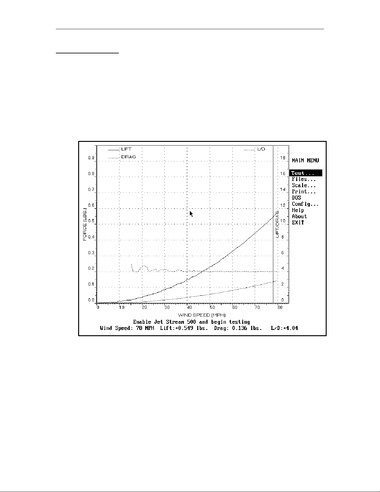
An optional IBM PC graphical computer interface is also available which allows full functional
control of the wind tunnel. The software is an easy to use menu interface with built-in help that
will allow you to quickly master the features of the Jet Stream 500 (see Figure #1 below). The
lift and drag forces will be displayed graphically in real time with respect to the wind velocity.
L/D and C(x) can also easily be displayed graphically to show the relative performance of aircraft
wings and automobiles. The graphical and tabular data can then be printed or stored to disk for
further comparison.
PC Control Program Screen
Figure #1
CO2Project car test platform
An optional test platform is available that would allow CO2 project cars to be evaluated within the
Jet Stream 500. With a car mounted in the tunnel both the lift and drag can be monitored at
various wind speeds to improve model designs.

Jet Stream 500 13
Jet Stream 500 Specification
Tunnel: Seamless fiberglass construction for superior flow
Total tunnel length of 6' 2"
Dimensions derived from professional tunnel designs
Computer generated design
Maximum wind velocity of 80 MPH
Safety guards before and after the propeller
Test Area: Measures 5.25" - h, 5.25" - w, 16.0" - d
Flow straightener before and after the test area for linear wind flow
Clear unobstructed 3 sided viewing area with reflective bottom
Measures both lift (+/-) and drag up to 1 lb. (0.001 lbs. resolution)
Airfoil angle adjustment +/- 30°(5°resolution), without removing model
Optional Test bed supports CO2project cars
Motor: 1 HP, 110 volt ball bearing AC motor for long life
10.5" - 3 blade high speed nylon propeller
Microprocessor controlled for constant wind speed
Instrumentation: Lift and drag forces measured via precision strain gages
Wind speed measured and controlled via pitot tube (1 MPH resolution)
Data is collected by a microprocessor with a 10 bit A/D converter
Displays values in Metric or English units
Controls: Control panel plugs into the tunnel for remote manual control
Simple start and stop test controls
Manually adjustable wind speed via control dial
Display constantly displays lift, drag, and wind speed in real time
Lift/Drag (L/D) is also calculated and displayed in real time
Security key limits the tunnel to supervised access
Electronics: 11 MHz, 8032 Microcontroller with 16k of ROM
11 channel, 10 bit A/D converter
RS 232 interface @ 2400 baud
4 line by 20 character LCD panel
0 - 1 PSI differential pressure transducer to measure and control the wind speed
0 - 1.8 lb. strain gages to measure the model's lift and drag
Solid state relay motor speed controller
Optional Software: Easy to use menu driven graphical interface with built-in help
Graphically displays lift, drag, L/D, and C(x) with respect to wind speed
Overlay graphical test results for quick comparison
Displays graphical results in Metric or English units
Data can be imported to most spreadsheets for further analysis

Jet Stream 500 14
Technical Information
The Jet Stream 500 was developed by researching existing wind tunnel designs which are
currently used by aerodynamic research companies. With the help of their research, we were able
to develop a professional design at a reasonable cost. The main tunnel was constructed with a
seamless fiberglass shell and finished off with a gel-coat interior for a smooth finish which is
critical in a small wind tunnel design.
The test bed can easily be removed from the tunnel for simple access in mounting and unmounting
test models. With other tunnel designs, the test model must be mounted to the test area where
working room is limited. All of the sensitive electronic sensors are located inside the test bed so
you won't have to worry about breaking wires or damaging sensors.
Control Electronics
A microcontroller is used to control, monitor, and display the information on the LCD panel. The
microcontroller is an Intel 8032 design which is an 8 bit processing unit with built-in RAM,
UART, timers, and interrupt controller. Attached to the 8032 is a 16k EPROM which is used for
both the control program and look up tables. A 10 bit, 11 channel Analog to Digital converter
(A/D) is connected to the 8032 via serial link. Only 4 of the 11 channels are currently in use. The
A/D converter is capable of sampling the data and transmitting the data in as little as 30
microseconds. This would allow sampling rates as high as 33,000 samples per second for a single
channel. Since the Jet Stream 500 currently samples three of the channels every 10 ms, the
sampling rate is 300 samples per second. The LCD panel is a 4 line by 20 character which is also
connected directly to the 8032 microcontroller.
Force Sensors
The electronic sensors are used to measure the lift and drag by using precision strain gages and
high gain amplifiers to measure the forces exerted on the test model. These forces change the
resistance of the strain gages, and the voltage measured across the resistance is measured with a
high gain amplifier. Since the change in resistance is very slight, amplifiers are needed to
measure the changes before the analog to digital (A/D) converter can measure the force. Since the
voltage output is directly proportional to the force, the voltage is in direct relation to the test
model's force. Both the lift and drag forces are measured the same way except the lift sensor must
be capable of measuring positive as well as negative forces. Since an airplane wing can produce a
positive (upward) lift and a negative (downward) lift, this sensor is mounted so it can measure
forces in both directions. Without this, we would only be able to measure lift in one direction.
Since the wind speed can only be in one direction, the drag is measured in the positive direction
only.
Jet Stream 500 15
Wind Speed Sensor
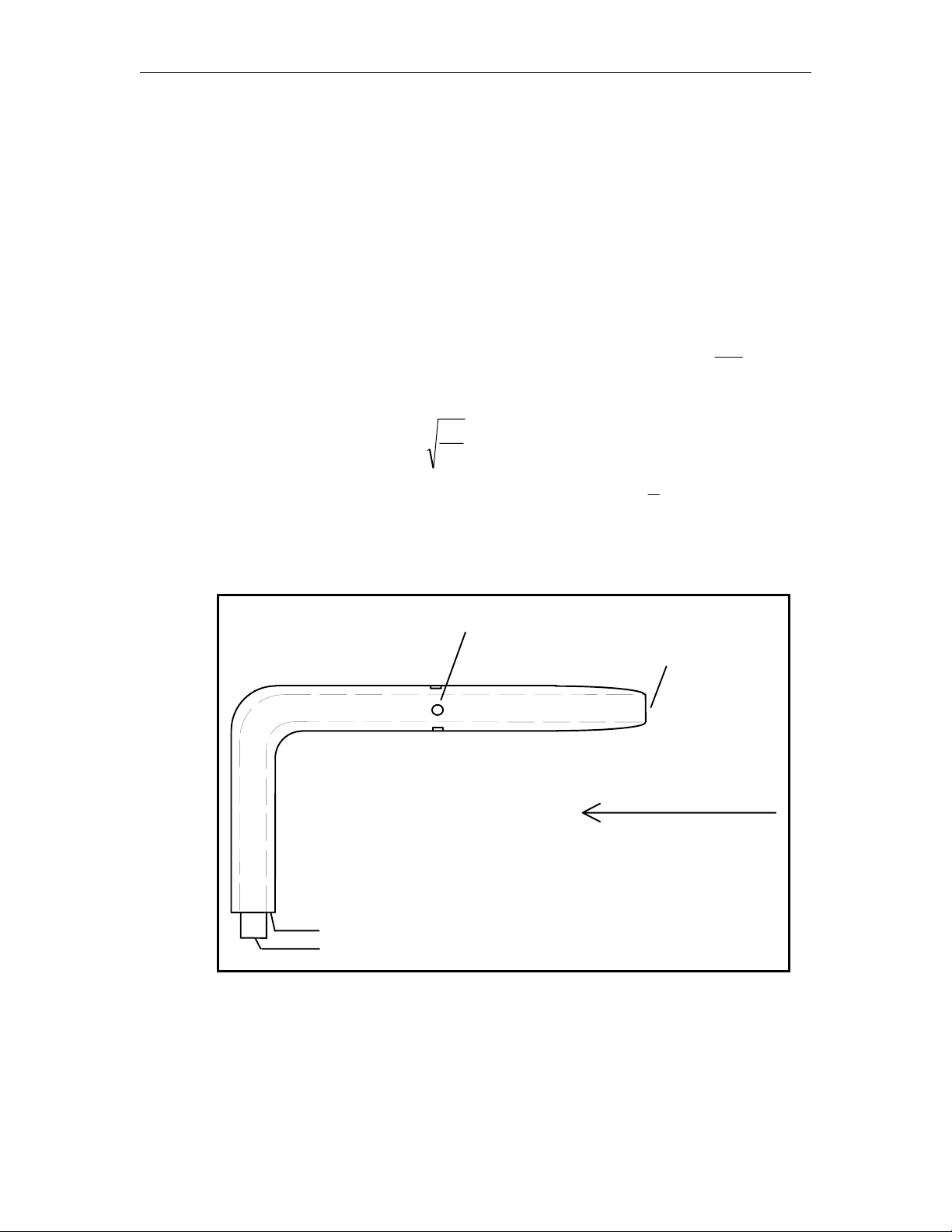
The wind speed is measured with the use of a static pitot tube and a precision differential pressure
sensor. This combination allows precise measurement of the wind speed within the tunnel. The
pitot tube is the metal tube that is bent at a 90 degree angle located in front of the test area. This
tube is modeled after those used on airplanes today. The tube actually contains an inside tube to
measure the air pressure pointing in the direction of the wind (the active pressure), and the outside
tube measures the air pressure of the tunnel (static pressure) (see Figure #2 below). Measuring
the difference between these two pressures (active - static pressure) gives an accurate
measurement of the wind speed. A precision pressure sensor is used to measure the very small
differences in pressure. Since the pressure of a 10 MPH wind creates less than .002 psi, the
sensors are very sensitive. Even changes in room temperature can affect the results of the sensors.
The output of the pressure sensor is amplified 1300 times so the A/D converter can properly read
the wind speed. The wind speed is not in direct relation to the pressure (p) ()pv
=
ρ
²
2, where ρ
is the density of air at room temperature and v is the velocity of wind. As you can see, the
relationship between pressure and wind speed is the wind velocity is proportional to the square
root of the measured pressure ()vp
=2
ρ
. This conversion is done within the microprocessor
by reading in the differential pressure (p), multiplying by a constant 2
ρ
, and taking the square
root.
Static Pitot Tube used to measure wind speed
Static Pressure Port
Active Pressure Port
Wind Direction
Static Pressure
Active Pressure
Figure #2

Jet Stream 500 16
Wind Speed Control
The microprocessor uses the wind speed to control the speed of the fan. By comparing the desired
wind speed (set by the wind speed control dial) to the actual speed (measured), the microprocessor
determines the error between the two speeds and adjusts the speed of the fan accordingly. This is
done by using simple velocity PID control algorithm by combining the proportional (P), integral
(I), and differential (D) velocity error signals to derive the output control to the fan. The
proportional error signal is derived from the error between the current wind speed and the desired.
For example, if the current wind speed is 25 MPH and the desired is 35, the proportional error
would be 10 (35 - 25). Using a proportional control algorithm is acceptable for most control
systems, but is not very good at quickly reducing the error. To improve the system response the
integral and differential terms are added. The integral error term is calculated by factoring the
error signal with respect to time. The longer the error signal persists the larger the integral term
becomes. This term is responsible for rapidly changing the output signal if the error is not
reduced quickly. For example, if the proportional error of 10 lasted for 100 milliseconds
generated an error of 5 and the error is not reduced after time, the integral error becomes 10, 15,
25, etc. The final error signal is derived from the differential term. This term adjusts the error
signal depending on the rate of change of the measured error. If the error signal varies too slowly,
the differential term is increased to speed up the response, but if the error term is changing too
quickly, the differential term is reduced to slow the response. This term is useful in adjusting the
error output depending on how quickly the system responds to the output. For example, if the
current error is changing slowly and the error signal is large, the output signal is increased to
quickly adjust. If the change in error is large but the error is small, the output signal is reduced.
Combining the three error signals into one is called a PID control system. Using a velocity PID
control is a quick and efficient method for controlling the wind speed in the tunnel.
Once the actual and desired speeds are identical, the wind speed error becomes zero and the fan
speed stabilizes to maintain a constant wind speed. If the line voltage should fluctuate during a
test, the actual wind speed will drop and the microprocessor will detect the error and add more to
the fan control to compensate. All of this is repeated every 1/10 of a second to maintain a stable
and accurate wind speed.
Jet Stream 500 17
Fan Motor Control
The fan motor is made up of a 1 HP, 110 volt AC industrial motor. The speed of the fan motor is
controlled by using a solid state relay that feeds power to the motor. To control the motor's speed
accurately, it is necessary to have the microprocessor monitor the wind speed and control the
motor directly. This is done by controlling how much power reaches the motor. Since the motor
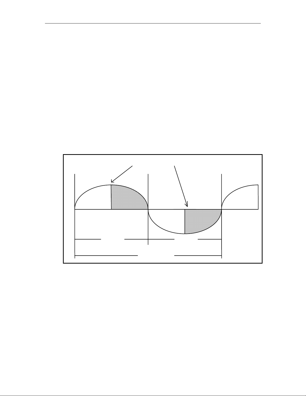
is an AC motor, we are able to control how much power was delivered by chopping the AC power
into small segments and passing just enough power to the motor to run at the desired speed (see
Figure #3 below). This is done by having the microprocessor detect when the 110 volt AC wave
reaches 0 volts (the crossover) to start a timer. If only half of the power is needed, the timer
would wait for enough time to pass before turning on the solid state relay. Because a solid state
relay stays activated until the voltage crosses zero volts, we are able to send a controlled amount
of power to the motor which allows us to directly control the fan motor speed. Since we use 60
cycle power in the US, the process must be repeated twice for every cycle at 60 times a second
(every 8.333 milliseconds). The microprocessor is very busy making sure the fan is at the proper
speed. As you can see, by varying the microprocessor timer values from 50% to 60%, different
wind speeds can be generated.
60 Cycle AC Wave form
8.33 ms. 8.33 ms.
Relay Turned On
1/60 Cycles
+
-
0
Figure #3

Jet Stream 500 18
Troubleshooting
LCD does not display information
•Check to see that the control panel fuse is not blown.
•Check to be sure the control panel is properly plugged in and turned on.
Calibration Error is displayed
•Be sure the test bed is properly secured.
•Check the pitot tube for blockage or damage.
•Make sure the wind tunnel intake or exhaust ports are not blocked.
•Check that the 9 pin data cable is plugged into the control panel, test bed, and secured.
Numbers are erratic
•Low wind speeds may give erratic L/D results. Wind speeds greater than 30 MPH are
recommended for proper L/D measurements.
•Make sure the model is firmly attached to the test arm. Vibrations can cause erratic results.
•Large test models may cause excessive turbulence within the tunnel and cause the model to
vibrate. Reduce the size of the model and re-test.
•Check to see that the wind tunnel is on a stable platform and all of the feet are properly
adjusted.
System Error
•If a system error occurs, be sure that the test model does not weigh more than 1 lbs. Oversize
models may place to much weight on the instrumentation. If problems persist, call
Interactive Instruments for further instructions.
Wind Speed not controllable
•Check the pitot tube for blockage or damage.
•Check that the 9 pin data cable is plugged into the control panel, test bed, and secured.
Tunnel Not Connected is displayed
•Check that the 9 pin data cable is plugged into the control panel, test bed, and secured.
Fan not running
•Be sure the fan power cord is properly plugged into the rear of the control panel.
•Check to see that the fan fuse is not blown.
Angle of Attack not adjustable
•Check that the wind speed is at zero MPH before making adjustments to the angle of attack.
•Be sure to press in on the adjustment knob to link the knob with the test area.
Circuit Breakers keep tripping
•Be sure the wind tunnel is plugged into an outlet capable of 15 amps or more.

Jet Stream 500 19
Limited Warranty
Interactive Instruments, Inc. warrants the Jet Stream 500 against defects in material and
workmanship for a period of one year from receipt by the end user (proof of purchase
required). If Interactive Instruments, Inc. receives notice of such defects during the
warranty period, Interactive Instruments will either, at its option, repair or replace
products which prove to be defective.
Should Interactive Instruments be unable to repair or replace the product within a
reasonable amount of time, customer's alternative exclusive remedy shall be a refund of
the purchased price upon return of the product.
If this product was purchased as part of a system in a coordinated shipment or as a
system add-on, it is warranted against defects in material and workmanship during the
same period as the system.
Exclusions
The above warranty shall not apply to defects resulting from:
improper or inadequate maintenance by customer; customer-supplied software or
interfacing; unauthorized modification or misuse; operation outside of the environmental
specifications for the product; or improper site preparation and maintenance.

Jet Stream 500 20
Glossary
A/D Converter The component that converts analog signals from the force
and pressure sensors and converts them to digital data for the
microprocessor.
Angle of Attack A vertical adjustment that can be made to the model under test
to vary the angle of the model with reference to the wind
direction.
Control Panel The main control panel that is used to control the operation of
the wind tunnel.
Data Cable 9 pin cable that connects the test bed to the control panel.
Drag Force exerted on the model in the same direction of the wind.
Error Condition Prompts are displayed on the LCD panel when the controller
recognizes an error condition.
Fan A 3 blade 10.5" propeller used to generate the wind speed.
Force Sensor Electrical sensors that are used to measure the lift and drag
forces exerted on the test model.
LCD Liquid Crystal Display which is used to display the test results
and error conditions on the control panel.
L/D Lift divided by Drag ratio is derived by dividing the drag
force into the lift. This ratio is commonly used to determine
the characteristics of airfoils.
Lift Force exerted on the test model that causes the model to raise
or drop due to the wind speed.
Microprocessor The digital controller that monitors the wind speed, model
forces, control panel functions, updates the LCD panel, and
performs the required calculations for operation.
Static Pitot Tube A tube that is used to sample the static and active pressure in
an air stream to determine the current wind speed within the
tunnel (see Pressure Sensor).
Power Cord 110v power cord which powers the control panel and fan
motor.
Pressure Sensor The sensor that measures the static and active pressures from
the pitot tube so the pressure difference can be measured by
the microcontroller to determine the wind speed.
Security Key A key that is located on the control panel that disables the
operation of the wind tunnel when locked.
Stall The condition where the airfoil cannot produce enough lift
because of excessive turbulence due to the angle of attack
and/or the wind speed.
Strain Gage See Force Sensor.
Test Area Area within the wind tunnel where the test model is placed.
Test Bed Area within the wind tunnel where the test model is mounted.
The test model is removable for easy placement of the test
model.
Test Model The model that is attached to the test arm on the test bed.
Test Arm The post that is used to mount the model under test to the test
bed.
Other manuals for Jet Stream 500
2
Table of contents
Other Interactive Instruments Industrial Equipment manuals


