TFP1241
Page 4 of 4
Copyright © 2005-2010 Tyco Fire Suppression & Building Products. All rights reserved.
5.
Verify that the Inlet Pressure Gauge
of the Pressure Regulator indicates
sufcient nitrogen cylinder pressure.
It is recommended that the nitrogen
cylinder be replaced whenever its
pressure falls to 200 psi or below.
NITROGEN CYLINDER REPLACE-
MENT PROCEDURE
Replace the nitrogen cylinder in accor-
dance with the following instructions.
1.
Close the control valve in the air sup-
ply trim to the system.
2. Close the Cylinder Control Valve.
3.
Remove the Model AMD-3 Device
from the Cylinder Control Valve by
slowly unscrewing the inlet connec-
tion to the Pressure Regulator.
4.
Following the steps outlined in the
caution below, replace the nitrogen
cylinder.
CAUTION
The following instructions with re-
gard to the nitrogen cylinder must
be strictly followed. Failure to do
so may result in personal injury or
property damage.
a. Secure the cylinder to a wall or
post, ensuring that it will not tip
or fall if accidently bumped.
b.
Inspect the Cylinder Control
Valve outlet for dirt, dust, dam-
aged threads, oil, or grease. Re-
move dirt and dust with a clean
cloth. If damaged threads, oil,
or grease are present, replace
the cylinder.
c.
Inspect the Pressure Regula-
tor inlet for dirt, dust, damaged
threads, oil, or grease. Re-
move dirt and dust with a clean
cloth. If damaged threads, oil,
or grease are present, have the
pressure regulator serviced by
an authorized agent of the Vic-
tor Equipment Company.
d.
With the cylinder securely in
place and while standing to
the side or rear of the Cylin-
der Control Valve, momentarily
crack open the Cylinder Control
Valve. This procedure is intend-
ed to blow out any foreign mat-
ter that may be inside the valve
outlet.
e.
Attach the Model AMD-3 Device
to the Cylinder Control Valve
and securely wrench-tighten.
5.
Open the Cylinder Control Valve in
accordance with Step 4 in the Op-
erating Procedure section.
6.
Open the control valve in the air sup-
ply trim to the system.
7.
Check the Pressure Regulator con-
nection for leaks.
Limited
Warranty
Products manufactured by Tyco Fire
Suppression & Building Products
(TFSBP) are warranted solely to the
original Buyer for ten (10) years against
defects in material and workmanship
when paid for and properly installed
and maintained under normal use and
service. This warranty will expire ten
(10) years from date of shipment by
TFSBP. No warranty is given for prod-
ucts or components manufactured by
companies not afliated by owner-
ship with TFSBP or for products and
components which have been subject
to misuse, improper installation, corro-
sion, or which have not been installed,
maintained, modied or repaired in
accordance with applicable Standards
of the National Fire Protection Asso-
ciation, and/or the standards of any
authorities having jurisdiction. Mate-
rials found by TFSBP to be defective
shall be either repaired or replaced, at
TFSBP’s sole option. TFSBP neither
assumes, nor authorizes any person
to assume for it, any other obligation
in connection with the sale of products
or parts of products. TFSBP shall not
be responsible for sprinkler system de-
sign errors or inaccurate or incomplete
information supplied by Buyer or Buy-
er’s representatives.
In no event shall TFSBP be liable, in
contract, tort, strict liability or under
any other legal theory, for incidental,
indirect, special or consequential
damages, including but not limited to
labor charges, regardless of whether
TFSBP was informed about the pos-
sibility of such damages, and in no
event shall TFSBP’s liability exceed an
amount equal to the sales price.
The foregoing warranty is made in lieu
of any and all other warranties, express
or implied, including warranties of mer-
chantability and tness for a particular
purpose.
This limited warranty sets forth the
exclusive remedy for claims based on
failure of or defect in products, materi-
als or components, whether the claim
is made in contract, tort, strict liability
or any other legal theory.
This warranty will apply to the full
extent permitted by law. The invalidity,
in whole or part, of any portion of this
warranty will not affect the remainder.
Ordering
Procedure
Contact your local distributor for avail-
ability. When placing an order, indicate
the full product name, including de-
scription and Part Number (P/N).
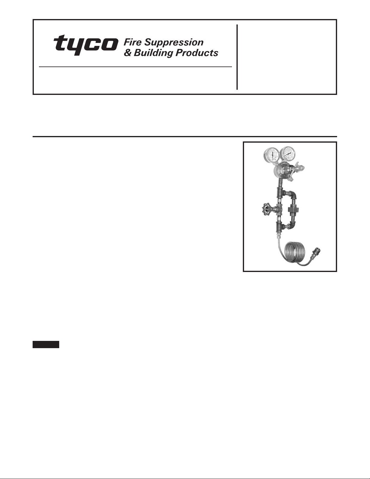
Model AMD-3 Device
Specify: Model AMD-3 Automatic
Nitrogen Maintenance Device,
P/N 52-328-2-001.
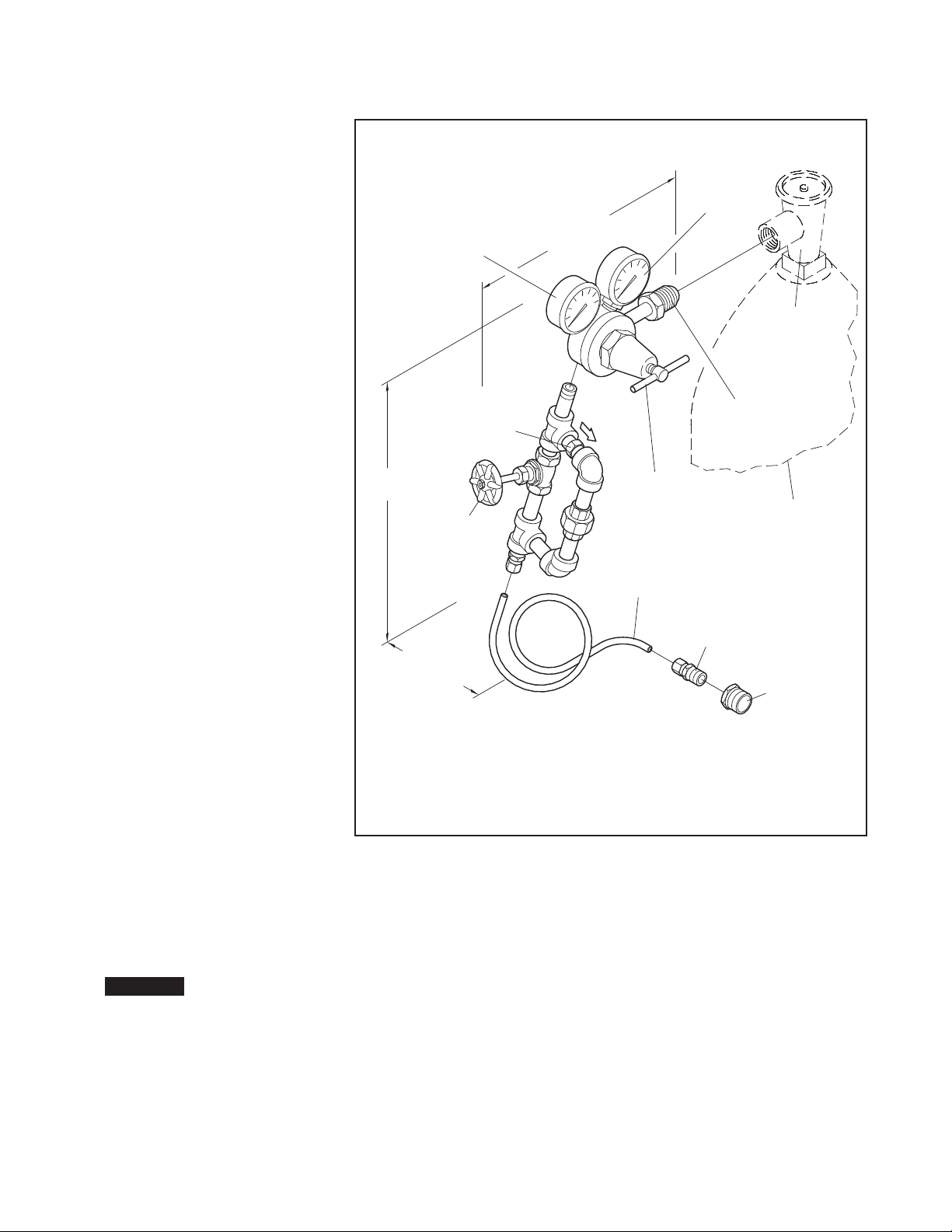
Replacement Parts
Specify: (description) for use
with the Model AMD-3 Automatic
Nitrogen Maintenance Device,
P/N (from Figure 1).