PRM NEWAGE 415 Series Instruction manual
415B12L062
WORKSHOP
MANUAL

2
PRM NEWAGE LIMITED
BARLOW ROAD
COVENTRY
CV2 2LD
ENGLAND
TELEPHONE: +44 (0)24 7661 7141
FAX: +44 (0)24 7661 1845
EMAIL: mail@prm-newage.com
WEBSITE: www.prm-newage.com
415B12L062 Manual
Issue: 1.2
Created By: S HYLANDS
Updated: February 2019
This manual contains proprietary information of PRM Newage Limited. It is intended solely for the information
and use of parties operating and maintaining the equipment described herein. Such proprietary information
may not be used, reproduced, or disclosed to any other parties for any other purpose without the express
written permission of PRM Newage Limited.
PRM Newage Ltd operates a policy of product improvement and therefore reserves the right to change
specifications without prior notification. Whilst every effort is made to ensure complete accuracy of the
information in this manual no liabilities for inaccuracies or the consequences thereof can be accepted by the
manufacturer or the distributor who supplied the manual.
The following international symbols are used in this service manual:
WARNING! THIS SYMBOL WARNS OF POSSIBLE PERSONAL INJURY
CAUTION! THIS SYMBOL WARNS OF POSSIBLE DAMAGE TO TRANSMISSION

3
CONTENT
INTRODUCTION ....................................................................................................................................................... 5
GENERAL DATA ........................................................................................................................................................ 5
Description........................................................................................................................................................... 5
Specification ........................................................................................................................................................ 5
Installation Drawing............................................................................................................................................. 6
IDENTIFICATION....................................................................................................................................................... 7
GENERAL SERVICE INFORMATION ........................................................................................................................... 8
Routine Maintenance .......................................................................................................................................... 8
Lubricants ............................................................................................................................................................ 8
Greases ................................................................................................................................................................ 8
Brake Fluid ........................................................................................................................................................... 8
Liquid Sealant ...................................................................................................................................................... 8
Fastener Tightening Torques ............................................................................................................................... 9
Axle Backlash ....................................................................................................................................................... 9
Tooling ................................................................................................................................................................. 9
SERVICING AND REPAIRS ....................................................................................................................................... 10
Seals................................................................................................................................................................... 10
Bearings ............................................................................................................................................................. 10
Cleaning ............................................................................................................................................................. 10
INSPECTION ........................................................................................................................................................... 11
Main Case and Arms .......................................................................................................................................... 11
Gears.................................................................................................................................................................. 11
Bearings ............................................................................................................................................................. 11
Threaded Parts .................................................................................................................................................. 11
PROCEDURES ......................................................................................................................................................... 11
Section ‘A’ – 415B12L062 Axle Assembly .......................................................................................................... 12
REMOVING & SERVICING THE CROWN WHEEL AND PINION. ........................................................................... 15
Section ‘B’ – Main Case and Differential Assembly ........................................................................................... 17
Servicing the Main Case and Differential Assemblies ...................................................................................... 19
Removing the Differential................................................................................................................................ 19
Servicing the Differential Assembly ................................................................................................................. 19
Section ‘C’ – Planet Carrier Assembly ................................................................................................................ 20
Servicing the Planet Carrier Assemblies........................................................................................................... 21
Removing the Annulus Gear ............................................................................................................................ 22
Section ‘D’ – Axle Arm, Hub and Brake Assemblies ........................................................................................... 22
Servicing the Axle Arm, Hub and Brake Assemblies......................................................................................... 24
Servicing the Brake Assemblies........................................................................................................................ 24
SPARES KITS ........................................................................................................................................................... 25

4
SPIRAL BEVEL GEAR TOOTH CONTACT .................................................................................................................. 27
Correct Pattern .................................................................................................................................................. 27
Incorrect Pattern ............................................................................................................................................... 27
NOTES ................................................................................................................................................................ 29

5
INTRODUCTION
Spare parts for Newage axles may only be obtained from the original equipment manufacturer and
not directly from Newage. Always quote your vehicle/machine serial number and axle serial number
–see section titled 'Identification'.
If possible, the repair/service should be carried out in a clean environment. Where this is not possi-
ble, and the work must be completed on site, appropriate measures must be taken to ensure that
dirt or foreign matter does not enter the unit. Newage axles are designed to operate in the arduous
conditions found in the construction industry; providing they are maintained regularly they will pro-
vide the service our customers expect from Newage products.
GENERAL DATA
Description
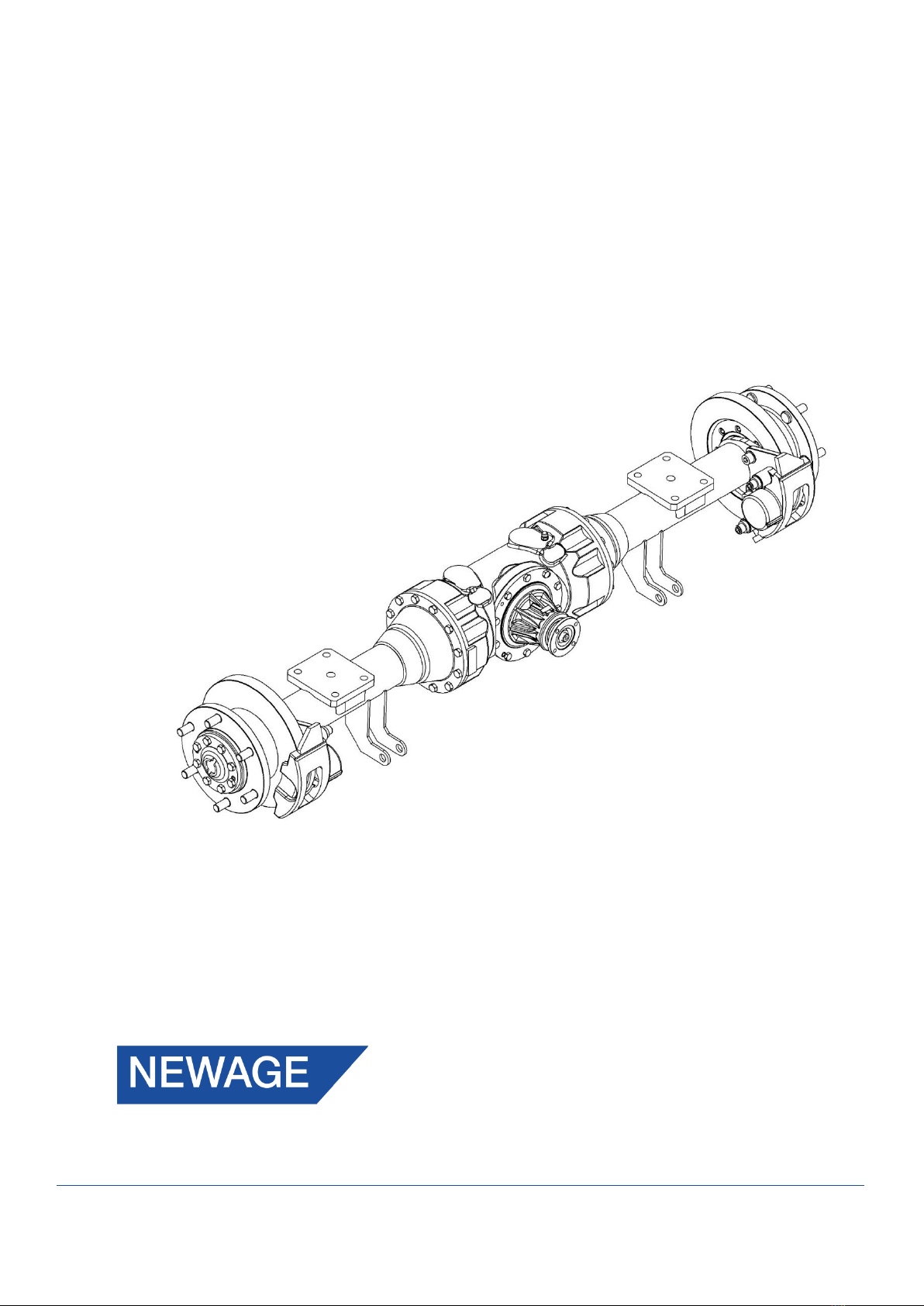
The 415 series axle is a double reduction unit featuring a Hydraulic Disc Braking system.
The 1st reduction Spiral Bevel Pinion and Crown Wheel driving a 4 Pinion Differential. Final drive is
transmitted via the 2nd reduction in-board Planetary Assemblies. The Axle Shafts are fully floating
(i.e. not subjected to wheel loads) with each Wheel Hub supported on opposed taper Roller Bear-
ings.
Specification
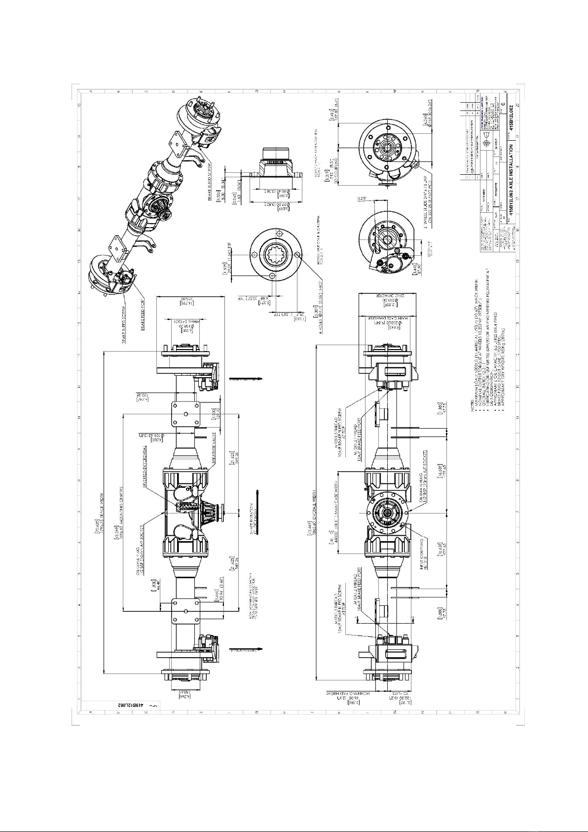
Overall Ratio
12.33:1
Input Flange
To suit Hardy Spicer 1310 Coupling
Wheel Fixing
6 studs: 3/4”x 16 UNF-3A on 222.25 mm (8.75”) PCD
Dynamic Axle Load Rating
Maximum load rating 5200 Kg (11440 lbs) based on 1793.75 mm (70.62”) wheel track
Service Brake
See Torque/Pressure Graph
Park Brake
Not Applicable.
Approximate weight
180 kg (397 lb) dry
Oil Capacity
6.5 litres (11.4 Pints)
6
Installation Drawing
7
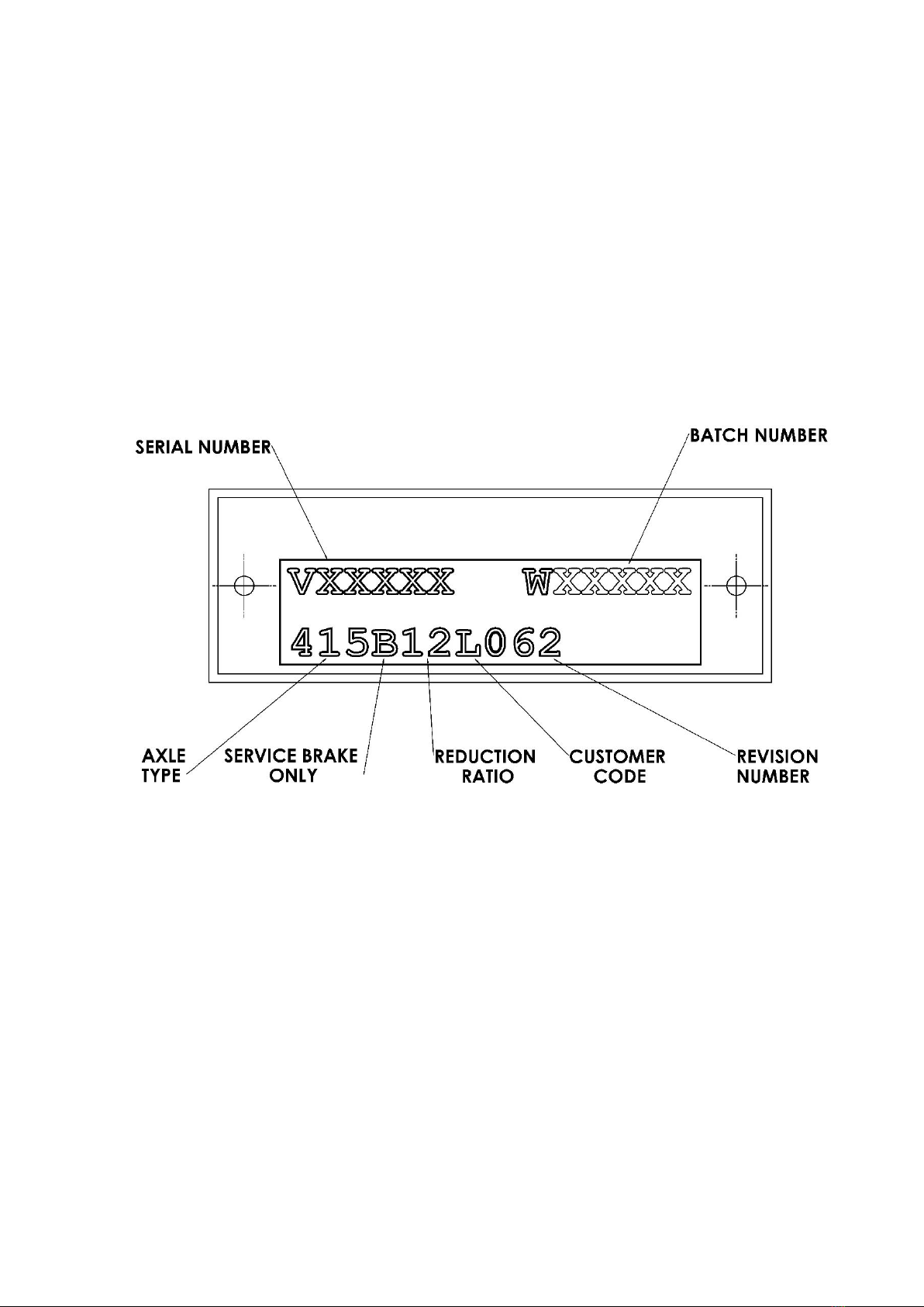
IDENTIFICATION
If spares are required, please quote the axle model, the vehicle/machine model and serial number
from the blue plate. 415 Axles are produced in a variety of configurations for individual customer
requirements; therefore, it is important to identify the Axle correctly.
The part number allocated to each Axle describes the basic specification as below:

8
GENERAL SERVICE INFORMATION
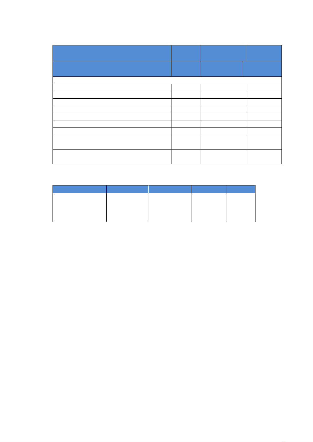
Routine Maintenance
Check
Frequency
Axle Oil change
After initial 300 Hrs
then every 1,000 Hrs
Axle Oil Level check
Monthly
Axle Shaft Bolts
Monthly
Brake Fluid change
Annually
Brake Fluid Level check
Monthly
Check Axle Arm/Main Case joint securing Bolts
Monthly
Check Wheel Hub Bearing adjustment
1,000 Hrs
Check Wheel Nut
Weekly
Visual check for oil leaks around joints and Seals
Weekly
Prop Shaft Bolts
Monthly
Lubricants
Only those lubricants shown below, or their direct equivalents must be used:
SAE 80W-90 Gear oil for operation in ambient temperatures
between 0°C and 30°C (32°F -86°F)
NOTE: An alternative engineering approved Gear oil may be used. Consult ‘PRM Newage’before
filling the axle.
The oil is added via the combined Filler/Level Plug positioned on the rear of the axle Main Case.
When installing new Unitized Hub Seals, ensure the outer surface of the seal and the inner diameter
bore of the Hub is free from grease. Use Loctite SF7063 Solvent Cleaner to degrease both before
fitment of the seal.
Greases
Smear grease between Oil Seal lips and ‘O’ Rings at major overhauls (with exception to the Wheel
Hub seals), or whenever a repair to these areas is performed.
Only those greases shown below, their direct equivalents or alternative engineering approved grease
must be used: Texaco Multifak EP2
Brake Fluid
The Axle Brakes operate with the fluid specification: FMVSS 116 DOT 4, SAEJ1703 and ISO4925 Brake
Fluid
NOTE: An ISO VG32 Mineral Hydraulic Fluid Should NOT be used under any circumstance.
Liquid Sealant
The Main Case/Axle Arm joint faces must be sealed with either of the following:
•Threebond 1207D Silicone Liquid Gasket
NOTE: An alternative engineering approved silicon sealant may be used.
For locking features, the following compound must be used:
•Loctite 243
NOTE: An alternative engineering approved locking compound may be used.
9
Fastener Tightening Torques
Fastener
A/F
(mm)
Torque (Nm.)
Torque (lb.
Ft)
Across
Flats
Newton Me-
tres
Pounds
Force Feet
Main Case Assembly
Axle Arm/Main Case High Tensile Bolts (M12)
19
146
107
Axle Shaft/Wheel Hub High Tensile Bolts (M12)
19
146
107
Brake Calliper mounting Grade S Cap Bolt (M16)
14
230
170
Calliper Carrier Cap Bolts (M16)
14
257
190
Differential assembly Nut (M10)
17
77
57
Pinion Housing Bolt (M10)
17
84
62
Drain and Level Plug (1/2” BSP)
10
16
12
Hub Assembly Lock Nut (M65) –(Special Tool
required TMFS13)
---
135
100
Input Drive Flange Drag Torque after collapsing
Spacer
30
1.92/2.48
17/22 lbin
Axle Backlash
Assembly
Pinion/Wheel
Drive Flange
P.C.D
Backlash
416-9820
416-2000
416-2010
415-9810 (415-
2180 & 250-
0910)
(HS 1310)
79.40mm
(3.125”)
0.22-
0.30mm
(0.009-
0.012”)
Tooling
The following tooling is used to aid in the servicing of the axle. These are available from the Original
Equipment Manufacturer.
TMFS13 Socket Spanner for Wheel Hub Bearing Lock Nut 010N651. The TMFS13 tool is available
from SKF stockists (M65 Stub Axle Locknut socket 19mm (3/4”) drive)

10
SERVICING AND REPAIRS
WAR WARNING: Before carrying out any service work always ensure that the engine is switched off
Before removal of the Axle for repair or overhaul, carefully study the following procedures. Use proper hand
tools, slings and hoists for the job. WORK SAFELY
Keep all work areas, tools and Axle clean. All oil should be drained into a suitable container. Wipe up any
spilled oil or fluids to prevent accidents. Wear correct safety equipment I.e. safety glasses and safety shoes
to guard against personal injury
IMPORTANT NOTICE: ONLY REMOVE BREATHER, OIL
DRAIN PLUG OR OIL LEVEL PLUG ONCE THE AXLE IS AT
AMBIENT TEMPERATURE. REMEMBER HOT OIL CAN
CAUSE BURNS –WORK SAFELY.
CAUTION: The above operations should be carried out by suitably qualified personnel and
strictly in accordance with the procedures detailed in the workshop manual.
Drawings showing all internal components are contained in the parts lists at the back of this manual.
Seals
Remove Oil Seals carefully to prevent damage if they are to be re-used, however to prolong the life
of the axle, it is best to replace these items.
Bearings
If removing taper roller Bearings for re-use keep them in matched sets and protect all Bearings from
contamination.
Cleaning
WARNING: If using cleaning solvents these can be toxic, flammable, a skin irritant or give off
harmful fumes. Avoid prolonged contact, vapour inhalation, or smoking. Failure to take care
can result in injury or death.
Rinse all metal parts in solvent to remove dirt, grease and oil.
Be careful to remove solvent from items before re-fitting.

11
INSPECTION
Main Case and Arms
Inspect for cracks. Check sealing surfaces for any imperfections, damage, etc. which will lead to oil
leaks. Check all threads for damage.
Gears
Inspect for any chipped, broken or cracked gear teeth, also for any excessive wear i.e. initial or
progressive gear pitting.
Bearings
Inspect for any damage, denting, initial or progressive pitting and over-heating. Each time a Bearing
is removed for inspection, or replacement it will be necessary to recalculate the required shim
thickness to pre-load the Bearings correctly, see Procedures for more information.
Threaded Parts
Inspect for stripped or damaged threads.
PROCEDURES
CAUTION: When re-assembling the Axle all threaded fasteners must be tightened to the
specified torques to prevent premature failure. Refer to Fastner Tightening Torque on page 9.
Some servicing operations can be carried out with the Axle still mounted to the vehicle (provided, of
course, that there is sufficient space); an example of this is the replacement or repair of the brake
assemblies. The repair or replacing the Differential, Planetaries or Arm assemblies however will
require the complete removal of the Axle from the vehicle.
If the details outlined below are carefully followed no difficulty will be found in stripping and
rebuilding the Axle. It is most important that all components are perfectly clean and in good
condition before reassembly.
CAUTION: All gears are supported by taper roller Bearings. Each time a bearing has been
removed for inspection, component repair or replacement it will be necessary to recalculate
the Shim thickness or adjust the Wheel and Differential Bearing to give the required pre-load.
Re-Shimming of the Axle is detailed under the Axle Shimming procedure.
12
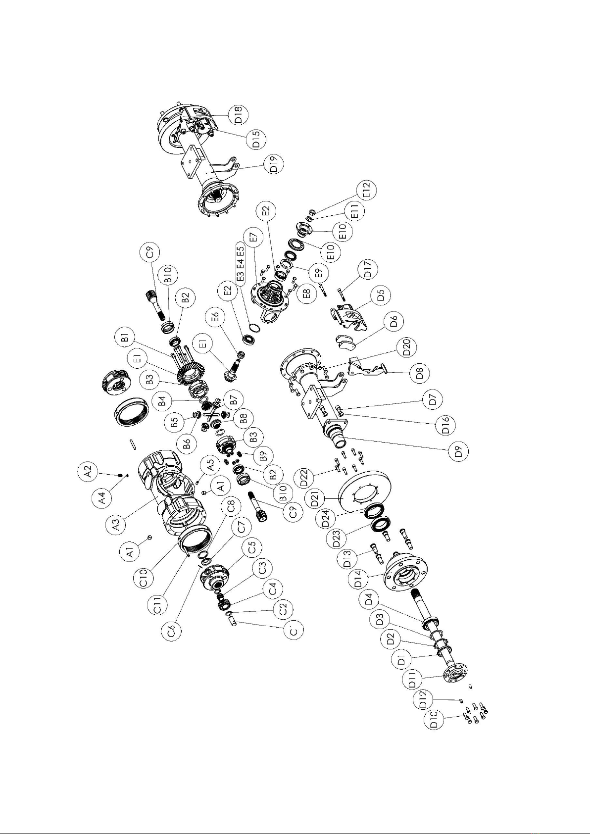
Section ‘A’ – 415B12L062 Axle Assembly

13
Item
Part No
Qty
Description
A1
0150250
2
½” BSP Level / Drain Plug
A2
CP1488
1
Breather
A3
415-0013
1
Main Case
A4
CP1224
1
Sealing Washer
A5
010-0040
2
Dowel
B1
0041023
8
Bolt M10 x 110 Long
B2
055C024U041H
2
Taper Roller Bearing
B3
350-9520
1
Differential Case
B4
250-2110
2
Thrust Washer
B5
250-2120
4
Thrust Washer
B6
360-2100
4
Diff. Pinion Wheel
B7
251-2130
2
Diff. Spider (Half)
B8
360-2090
2
Diff. Wheel
B9
0051006HT
8
Nyloc Nut M10
B10
415-2151
2
Bearing Adjuster Nut
C1
415-0250
6
Plannet Pin
C2
410-0271
12
Thrust Washer
C3
0562530
6
Needle Bearing
C4
418-0080
6
Planet Gear
C5
416-0060
2
Planet Carrier
C6
010-0070
6
Spring Dowel Ø 3 x 40
C7
410-1321
2
Spacer
C8
003-0100
2
Circlip Ø 60
C9
418-0090
2
Sun Gear
C10
418-0070
2
Annulus
C11
010-0190
2
Dowel Pin Ø 10 X 70
D1
010N651
2
Nut M65
D2
010W651
2
Lock Washer M65
D3
415-1440
2
Spacer
D4
0540604H
2
Taper Roller Bearing
D5
418-2500
1
Service Brake (LH) (Includes Brake Pad D6)
D6
418-2510
4
Brake Pad
D7
0081730
4
M16 x 30 Cap Head Bolt
D8
415-2401-LH
1
Brake Mounting Bracket (LH) (Includes Bolts D17 - 2 off)
D9
415-0035-LH
1
Welded Axle Arm Assy (LH)
D10
0041210HTP
16
M12 x 35 Long Bolt
D11
421-0100
2
Axle Shaft
D12
0211225
4
Dowel Ø 12 x 25
D13
415-0450
12
Wheel Stud ¾” x 16 UNF
D14
415-0041
2
Wheel Hub
D15
418-2540
1
Service Brake (RH) (Includes Brake Pads D6)
D16
0191013H
4
Hardened Washer M16 x 4 Wide
D17
See D8/ D18
4
Mounting Bracket Bolt (not available separately)
D18
415-2401-RH
1
Brake Mounting Bracket (RH) (Includes Bolts D17 - 2 off)
D19
415-0035-RH
1
Welded Axle Arm Assy (RH)
D20
0041210HTP
24
M12 x 35 Long Bolt
D21
415-0753
2
Brake Disc
D22
0081535L
16
M10 x 35 Long Cap Head Bolt
D23
0540751H
2
Taper Roller Bearing
D24
417-2850V
2
Oil Seal - Viton

14
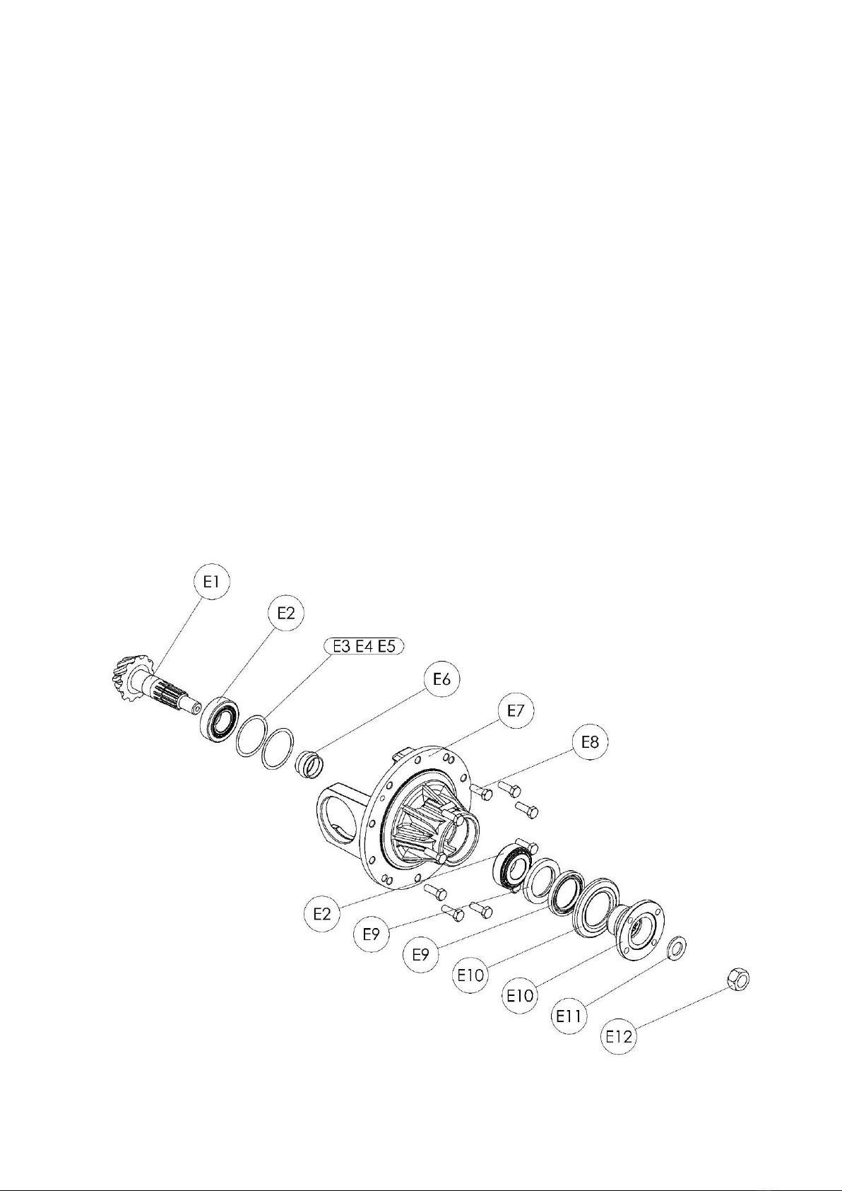
E1
416-9820
1
Crown Wheel and Pinion (Matched Lapped Set)
E2
055C020U043H
2
Taper Roller Bearing
E3
360-2210
As Req.
Shim 0.30 mm
E4
360-2290
As Req.
Shim 0.40 mm
E5
360-2350
As Req.
Shim 0.25 mm
E6
250-1050
1
Spacer
E7
415-2300
1
Input Pinion Cartridge
E8
0041009HTP
10
M10 x 30 Long Bolt
E9
002-0030V
2
Oil Seal - Viton
E10*
415-9810
1
Input Drive Flange Assembly (Includes 415-2180 & 250-
0910)
E11
009-0090
1
M20 Hardened Washer
E12
007-0130
1
M20x 2.5 Nyloc Nut
*NOTE: E10 can only be supplied as Assembly 415-9810 and comprises of Input Drive Flange 415-
2180 & Oil Seal Cover 250-0910.

15
REMOVING & SERVICING THE CROWN WHEEL AND PINION.
1. Remove the Drain Plug (A1) and drain the Axle Oil.
2. Remove both Axle Arm assemblies by removing 12 Bolts per side (D20). Withdraw the Plan-
et Carrier Assembly (see Section C), and Sun Gear (C9).
3. Remove 10 Bolts (E8) around the Pinion Cartridge. Using two M10 extraction Bolts (not
supplied), remove the Crown Wheel/Differential assembly through the Pinion Cartridge ap-
erture.
4. Remove the Pinion Nut (E12) from the Pinion Shaft (E1), along with the Washer (E11), and
the Coupling (E10).
5. Unpein 2 Adjuster Nuts (B10) and remove. Differential assembly will now be free to remove
from the Pinion Cartridge.
6. Drift Pinion (E1) through Cartridge and Inspect the Bearings (E2) for wear and damage. If
the inner Bearing on the Pinion head needs replacing, use a Bearing puller to extract the
cone. If the Bearing Cups or Oil Seals need replacing, they can be pressed or drifted out of
the Cartridge housing. Take care not to damage the Shims positioned behind the Bearing
Cup.
IMPORTANT: If any components are replaced a new Collapsible Spacer (E6) & Pinion
Nut (E12) must be used and the Crown Wheel/Pinion marking and backlash reset.
7. If the Crown Wheel and Pinion or Pinion Head Bearing (E2) are replaced, the following pro-
cedure needs to be carried out:
8. To check Shim size
(a) Note the new Pinion (E1) mounting distance (M.D.) on the head. (Approximately
87.5mm)
(b) Measure the new overall width of Pinion Head Bearing (E2). (Approximately
22.2mm)
(c) Note Pinion Cartridge (E7) mounting distance (Constant for 415 = 110.35mm).
(d) Shim thickness (E3, E4, E5) = 110.35 -(a)-(b) e.g. For theoretical normal shims:
110 - 22.2 - 87.5 = 0.65mm
9. Reassemble and tighten the Pinion Nut (E12) until the Collapsible Spacer (E6) collapses and
all the end float between the Pinion Bearings is removed. Note, the initial collapsed torque
on wrench should not be less than 245 Nm (180 lb.ft).
10. Continue to tighten the Pinion Nut until a pre-load of 59-98N (22lbf) for new Bearings, or
29.5-59N (6.6-13.2lbf) for used Bearings is obtained. The pre-load can be measured by bind-
ing a piece of string around the Coupling (E10) and measuring the load to turn the Coupling
16
with a Spring Balance (See diagram below). Alternatively use a Torque Wrench to achieve a
measured drag torque of 1.92/4.48 Nm (17/22 lbin).
11. To reset backlash:
i. Refit Crown Wheel and Differential assembly into the Pinion Cartridge and screw
new Differential Bearing Adjuster Nuts into position to remove all backlash from
the gear mesh.
ii. Adjust the Nuts to move the Crown Wheel out of mesh to achieve a backlash at the
flange specified on page 5.
iii. Tighten the Adjuster Nut opposite the Crown Wheel to 20 Nm (15lbft) and pein
both Differential Adjuster Nuts into the recess.
12. Clean the joint faces and refit the Cartridge assembly into the Main Case ensuring the rec-
ommended sealing agent is uniformly applied to the Flange faces and tighten to M10 Bolts
tightening torque.
13. To assemble the unit, reverse the above procedure.
14. Refill the Axle with the recommended Oil (See Page 5).

17
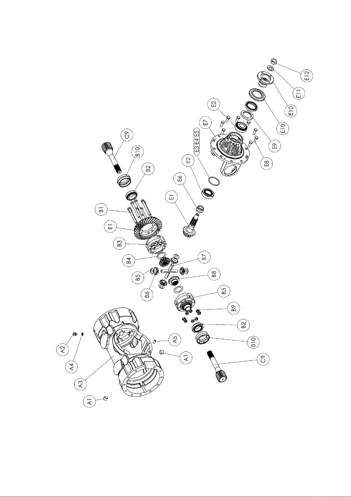
Section ‘B’ – Main Case and Differential Assembly
Item
Part No
Qty
Description
A1
0150250
2
½” BSP Level / Drain Plug
A2
CP1488
1
Breather
A3
415-0013
1
Main Case
A4
CP1224
1
Sealing Washer
A5
010-0040
2
Dowel
B1
0041023
8
Bolt M10 x 110 Long
B2
055C024U041H
2
Taper Roller Bearing
B3
350-9520
1
Differential Case
B4
250-2110
2
Thrust Washer
B5
250-2120
4
Thrust Washer
B6
360-2100
4
Diff. Pinion Wheel
B7
251-2130
2
Diff. Spider (Half)
B8
360-2090
2
Diff. Wheel
B9
0051006HT
8
Nyloc Nut M10
B10
415-2151
2
Bearing Adjuster Nut
C9
418-0090
2
Sun Gear
E1
416-9820
1
Crown Wheel and Pinion (Matched Lapped Set)
E2
055C020U043H
2
Taper Roller Bearing
E3
360-2210
As Req.
Shim 0.30 mm
E4
360-2290
As Req.
Shim 0.40 mm
E5
360-2350
As Req.
Shim 0.25 mm
E6
250-1050
1
Spacer
E7
415-2300
1
Input Pinion Cartridge
E8
0041009HTP
10
M10 x 30 Long Bolt
E9
002-0030V
2
Oil Seal - Viton
E10*
415-9810
1
Input Drive Flange Assembly (Includes 415-2180 & 250-0910)
E11
009-0090
1
M20 Hardened Washer
E12
007-0130
1
M20x 2.5 Nyloc Nut
*NOTE: E10 can only be supplied as Assembly 415-9810 and comprises of Input Drive Flange 415-
2180 & Oil Seal Cover 250-0910.
18

19
Servicing the Main Case and Differential Assemblies
Removing the Differential
1. Remove the Axle Arm Assemblies and Sun Gears (C9) –see Section D.
2. Remove the Axle Arm Planetary Assemblies - see Section C.
3. Remove 10 off Bolts (E8).
4. The Input Cartridge Pinion Assembly (E1 –E12) with the Differential Assembly (B1 –B9) can
be removed from Main Case (A3), ensuring that the 2 Dowels (A5) are either removed or
remain in the Main Case (A3)
5. The Adjuster Nuts (B10) are “peined” into the Input Pinion Cartridge Housing (E7).
6. Carefully “Un-pein” and removed the Adjuster Nuts (B10), using PR30332 tool.
7. The Differential Assembly (B1 –B9) can now be removed from the Input Pinion Cartridge
Housing (E7).
CAUTION: Great care must be taken when removing the Differential Assembly from Main Case.
Any damage to the Crown Wheel would be detrimental to the axles’ performance.
WARNING: The space constraints around the differential are very tight. The Differential
Assembly weights 20Kg, so ensure that you have a good grip on the casing before attempting
to remove the assembly from the case.
Servicing the Differential Assembly
1. Remove Nuts (B9) and Bolts if necessary (B1). The Crown Wheel (E1) is now loose and the
Differential assembly will split into 2 halves.
2. Remove the Differential Spider 2 off (B7) with the respective Differential Wheels (B8), Pin-
ions (B6), Wheel Washers (B4) & Pinion Washers (B5).
3. Inspect all Differential Wheels (B8), Pinions (B6), Spiders (B7), Bearings (B2), Wheel Washers
(B4) and Pinion Washers (B5) for damage and wear, replace if necessary.
4. To assemble, reverse the above procedure.
5. If new Differential Bearings (B2) are fitted, it will be necessary to reset the Bearing pre-load
and Crown Wheel/Pinion backlash.
NOTE: To reset the backlash, see page 13 for the procedure. The acceptable range can be found on
page 9.
20
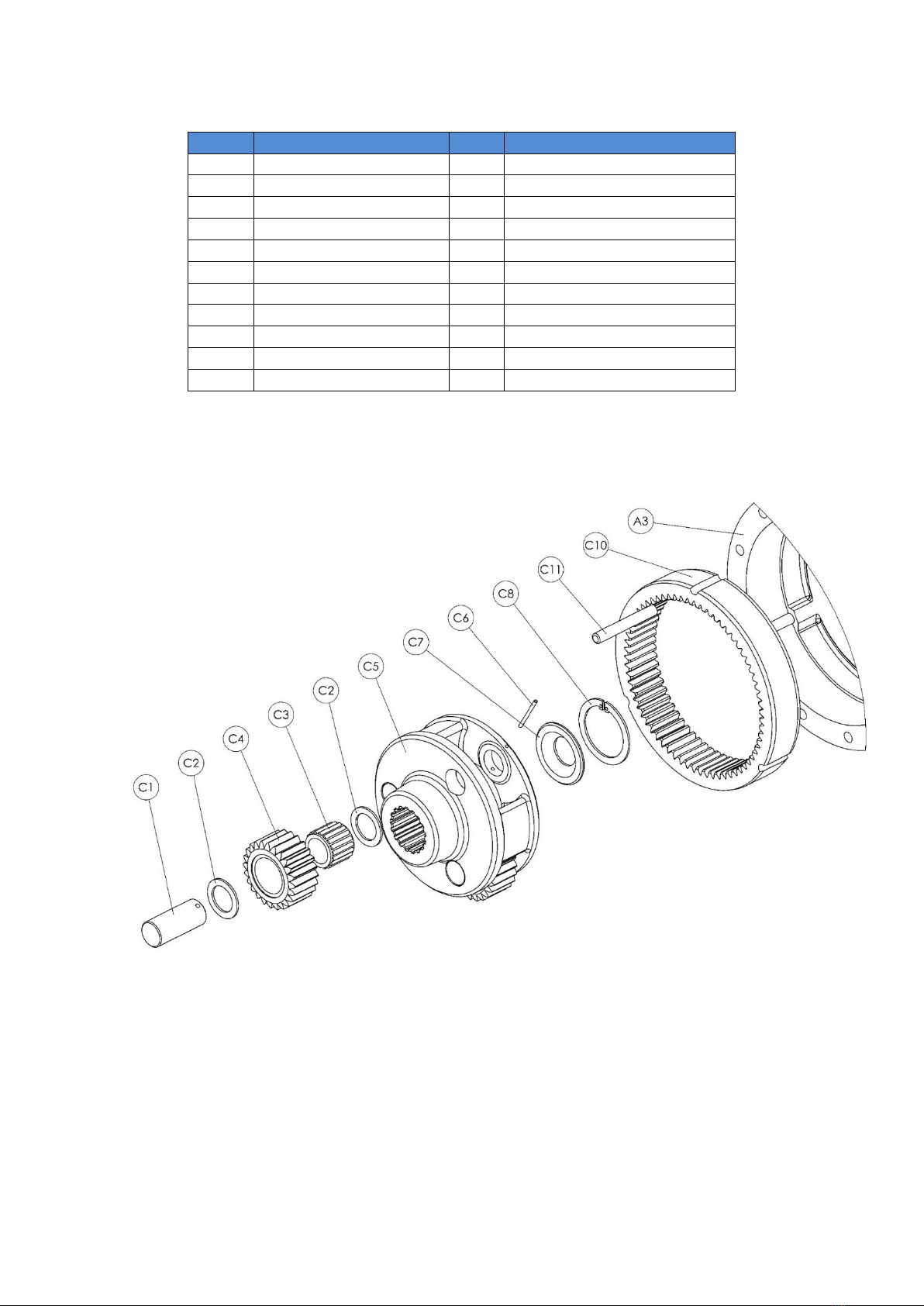
Section ‘C’ – Planet Carrier Assembly
Item
Part No
Qty
Description
C1
415-0250
3
Plannet Pin
C2
410-0271
6
Thrust Washer
C3
0562530
3
Needle Bearing
C4
418-0080
3
Planet Gear
C5
416-0060
1
Planet Carrier
C6
010-0070
3
Spring Dowel Ø 3 x 40
C7
410-1321
1
Spacer
C8
003-0100
1
Circlip Ø 60
C9
418-0090
1
Sun Gear
C10
418-0070
1
Annulus
C11
010-0190
1
Dowel Pin Ø 10 X 70
NOTE: Quantities stated per side (2 Assemblies per Axle)
This manual suits for next models
6
Table of contents


