Intercall 600 Original operating instructions
Intercall 600 & Intercall 700
Installation & Operation Guide
Documentation Issue 4.27
www.intercall.co.uk
N
o part of this leaflet may be reproduced without prior written consent and while every effort is made to ensure the information contained within this guide is
correct, no liability will be accepted for errors or omissions. This version supersedes all previous editions, latest editions may be downloaded from ou
r
website www.intercall.co.uk - Intercall is a registered trademark of Intercall Nursecall Systems Limited © 2005 all rights reserved.

Intercall 600/700 Installation & Operation Guide Issue 4.27 Page 1 of 78
Index
Introduction to Intercall Page
Introduction & Intercall 600 & 700 Inter-compatibility……………………3
Guide to Intercall 600………………………………………………………4
Guide to Intercall 700………………………………………………………5
Ordering Information….……………………………………………………7
Specials order codes and obsolete order codes……………………………..8
User Guide
Intercall 600 Call Points…………………..……………………………….. 9
Intercall 600 Display Unit………..…………………………………………10
Intercall 700 Audio Call Point..…………….………………………………11
Intercall 700 Audio Display Unit…...………………………………………12
Intercall 768 Audio Room Communicator………………………………… 15
Intercall 700 Call / Display Unit, Overdoor Lights & Other devices………16
Installation Guide
System Concepts & Network Cable Requirements…….…………………..17
Planning an Installation………………….………………………..……….. 18
Using the FJB to split the load…….……………………………………… 20
First Fix……………………………………………………………………..21
Second Fix…………………………………..……..….…………………... 23
System Tests………………………………………..….…………………... 24
L747 Installation Procedures..……………………..….…………………... 26
Intercall Components & Network Devices
L617 and L717 Power Supply Controller……………………..………….. 29
L7717 Large Power Supply Controller…….…………………..…………. 30
L622 Intercall 600 Standard Call Point…….………….………..………… 31
L622AN310 Intercall 600 Call Point with extended Inputs & Outputs…. 32
L733 Door Monitoring & Access Control Point….……………………….. 33
L737 Booster Power Supply..…………………………………..…………..34
L628 600 Series LCD Display………………………………..…………….35
L748 Large Corridor LED Display……………………………..…………..36
L746 Overdoor Light……………….…………………………..…………..36
L747 Universal Interface……………………………………….………….. 38
Alphanumeric Paging…………………………………………..………….. 39
RB1 Relay Board..……………………………………………..………….. 40
L714 Remote Sounder with Relay.……………………………..…………..41
DPU414 Thermal Printer.…………………….………………..………….. 42
FJB2 Fused Junction Board……………..…………….………..…………..43
L758 Audio LCD Display……………………………………………..……44
L722 Call Point…..……………………………………………..…………..45
L634 Network Input/Output Module….………………………..…………..45
L752 Audio Call Point…………………………………………..………….47
L762 Audio Call/Display Unit…..……………………………...…………..48
L768 Room Communicator Unit..……………………………...………….. 49
CMS Lite Call Management Software for Windows……………………….50

Intercall 600/700 Installation & Operation Guide Issue 4.27 Page 2 of 78
TIR4 Infra Red Trigger..………………………………………..…………..51
LIMKIT System Configuration Kit (including software)……..…………... 52
SCP Slave Call Point..…………………………………………..…………. 53
SRP Slave Reset / Present Point………………………………..…………. 54
CS1 Ceiling Pull Switch………………………………………..………….. 55
PIR1 Passive Infra Red Detector (For Bed monitoring)………..…………..56
Configuration Guide
System Configuration……………………………………………………… 57
Display Menu Settings…………..……………………..………….………..59
Zoning Configuration.…………..……………………..………….……….. 63
Zoning Examples…………..…………………………..………….………..65
Factory Text & Call Point Address Setting……………………..………….71
Setting the User ID on the TIR4 Triggers…………………………………..52
L617 / L717 System Configuration Switch Setting……………………….. 73
Fault Finding Guide
Call Point Faults……..……..…..………………………………………..….74
Display Unit Faults……………..……………………………………..……75
Power Supply Faults…………………………………………………..……76
L747 Interface Faults………………………..…………………………..….77
Network Faults: Data corruption / Volt Drop / Audio Faults……………....78

Intercall 600/700 Installation & Operation Guide Issue 4.27 Page 3 of 78
Introduction to Intercall.
INTERCALL is one of the most advanced range of nursecall systems available today. They couple
functionality with the most up to date reliable electronic technology available. Intercall have revolutionised
nursecall by providing simple to install and operate systems, which are very competitively priced and out
perform practically all other systems available today. Indeed the Intercall 600 system is the best selling
nursecall system within the UK
Since the introduction of Intercall in 1988, we have made people aware that there can be a more flexible,
more efficient, more effective way of using nursecall than ever before
This leaflet covers our two most advanced addressable call systems, the Intercall 600 and the Intercall 700.
Both systems are so flexible, that from the smallest home to the largest hospital, we have a solution to your
particular requirements. The systems may be completely re-configured, at any time, so now you can choose
how to manage patient and staff call requirements and change them as you wish.
We recommend that you read the following pages as they describe how you can make the most of your
Intercall Nursecall system.
Intercall 600 and 700 Inter-compatibility.
Intercall 600 and Intercall 700 systems share several network devices. The following table highlights the
inter-compatibility between the two systems.
Part No Description 617
PSU 717
PSU Network
Cable IR
Receiver
L622 600 Series Non Audio Call Point (Mk2) 99* 2 wire 8
L722 600/700 Series Non Audio call point with Infra Red 992 wire 9
L732 600/700 Series Non Audio call point with IR + Aux 992 wire 9
L722DK 600/700 Door Monitoring Point 992 wire 8
L617 600 Series Master Power Supply 982 wire 8
L733 600/700 Series Door Monitor & Access Control Point 992 wire 8
L717 700 Series Master Power Supply 892 wire 8
L746 600/700 Triangular Overdoor Light 992 wire 8
L746s As above with integral sounder 992 wire 8
L737 600/700 Series Booster Power Supply 992 wire 8
L752 700 Series Audio Call Point with Intercom 894 wire 9
L758 700 Series Audio Display Unit with Intercom 894 wire 8
L762 700 Series Audio Call / Display Unit with Intercom 894 wire 9
L768 700 Series Room Communicator 894 wire 8
L628 600 Series Display Unit (Mk2) 99* 2 wire 8
L634 600/700 Series Network Input/Output Module 992 wire 8
L748 700 Series Corridor LED Display Unit 892 wire 8
FJB2 Fused Junction Board Unit (Mk2) 994 wire 8
L747 600/700 Series Universal System Interface 992 wire 8
L714 600/700 Series Remote Sounder 992 wire 8
PIR1 Passive Infra Red Bed Monitor 992 wire 8
SCP Slave Call Point 99- 8
SRP Slave Reset/Presence Point 99- 8
RB1 Relay Board 992 wire 8
Due to the continued development programme on the Intercall range of products, please contact the sales office for the
latest information.
* Only applies to Mk2 products manufactured after August 2003
Intercall 600/700 Installation & Operation Guide Issue 4.27 Page 4 of 78
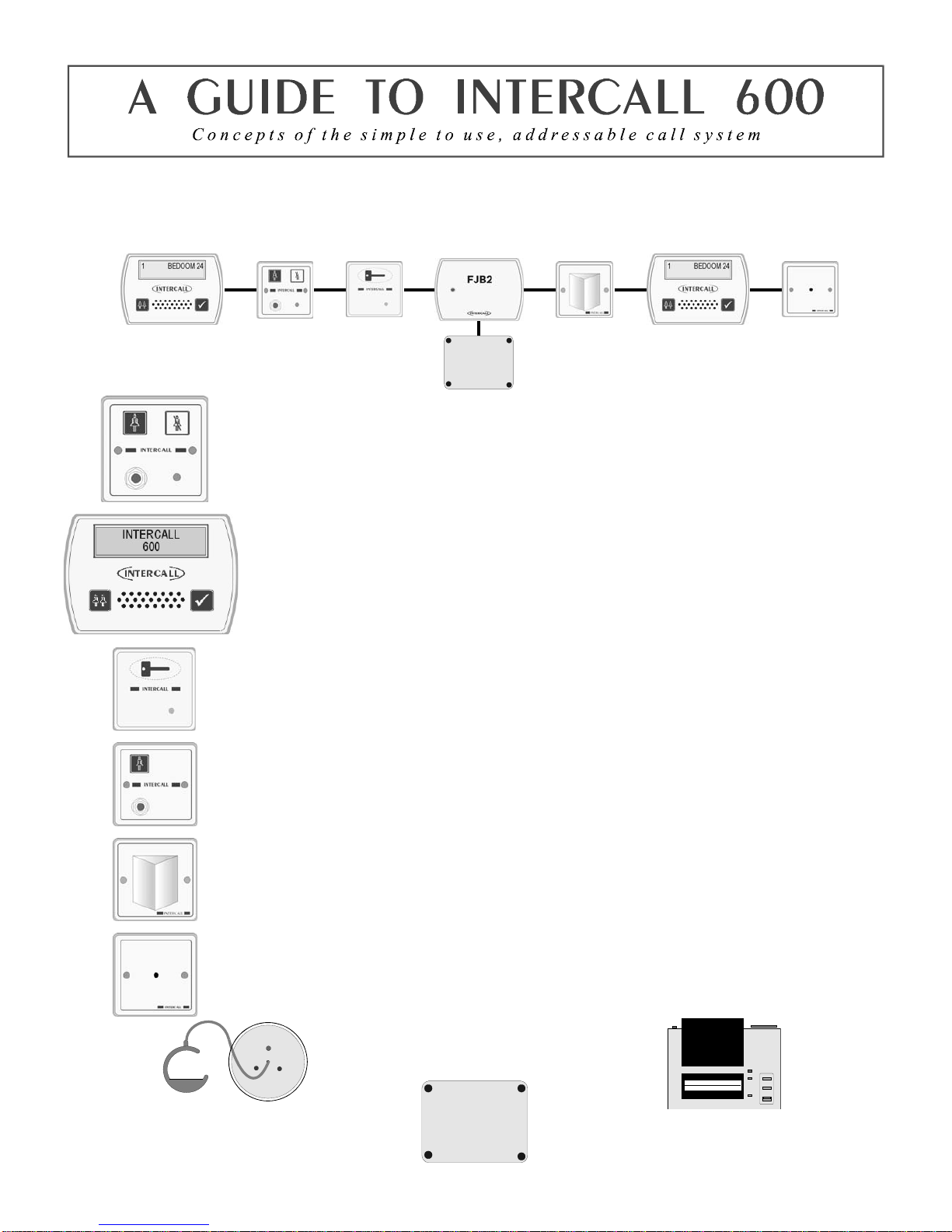
The INTERCALL 600 is our most popular addressable call system, coupling flexibility with ease of use, it provides a
complete solution that out performs practically all other systems available today. Being an addressable system, it
requires only one two core connection to network devices and operates at 12voltsDC. The room descriptions may be
programmed using a PC compatible laptop computer or similar which can be programmed on or off site as required.
L622 Standard Call Point.
A Call Point is required for every individual call location on the system. It features six levels of
call, multi-colour re-assurance LED & ‘call follower’ sounder. The industry standard trigger
socket will accept pear leads, pressure mats, portable radio triggers and a host of other triggering
devices. Options which must be specified when ordering include: Magnetic Key reset (L622M)
Emergency call only. Non-latching call points are available for telephones etc. see pages 31 & 45
L628 LCD Displays.
A Display Unit is required in every location where calls are to be shown and the alarm is to
sound. It features LCD display with backlight, multi-level adjustable alarm, day/night volume
control, ‘Priority’ alarm tone for specific call locations, configuration menus and an output
which can be connected to trigger external equipment. All displays are identical but can be
configured on site to operate independently. see page 35
L733 Door Monitoring & Access Control Point.
Generally used to monitor fire doors and main entrances for unauthorised entry or exit. Token
allows door to be opened by authorised personnel without sounding the alarm and isolated to
allow the door to be left open if required. Supplied with two magnetic tokens. See page33
SCP Slave Call Point.
Slave call points are used to cover several beds in one room or ward where each individual bed
does not require a separate identity on the call system. Units must be wired back to a standard call
point to provide the reset and to generate the call identity. see page 53
L746 Overdoor Light.
Overdoor lights are an optional item normally positioned above the door in a corridor to indicate
the status of the call point(s) within the room. The L746 can be used to monitor several call point
addresses and are ideal for ‘end of corridor’ indication. The L746S Unit is fitted with an integral
sounder. see page 36
L714 Remote Sounder with relay.
Remote Sounders are used in areas where only an audible alarm is required. The sounder is similar
in operation to the L628 with limited zoning facilities. Any assistance or emergency call on the
system will over-ride the standard call tone. The unit is fitted with a relay which provides N.O
and N.C ‘dry’ contacts. see page 41
CS1 Ceiling Pull Switch
Connects to call point for en-suite rooms
and bathrooms/toilets See Page 55
L717 & L737 Power Supply & FJB2
Provides power for system & holds back up
b
attery. Laptop connects to L717 to configure
system. L737 is a booster PSU required for
larger systems See Page 31
Printers and alphanumeric pagers
Printers and alphanumeric pagers may be
connected to the system with the L747
universal interface. See Page 36
Intercall 600/700 Installation & Operation Guide Issue 4.27 Page 5 of 78
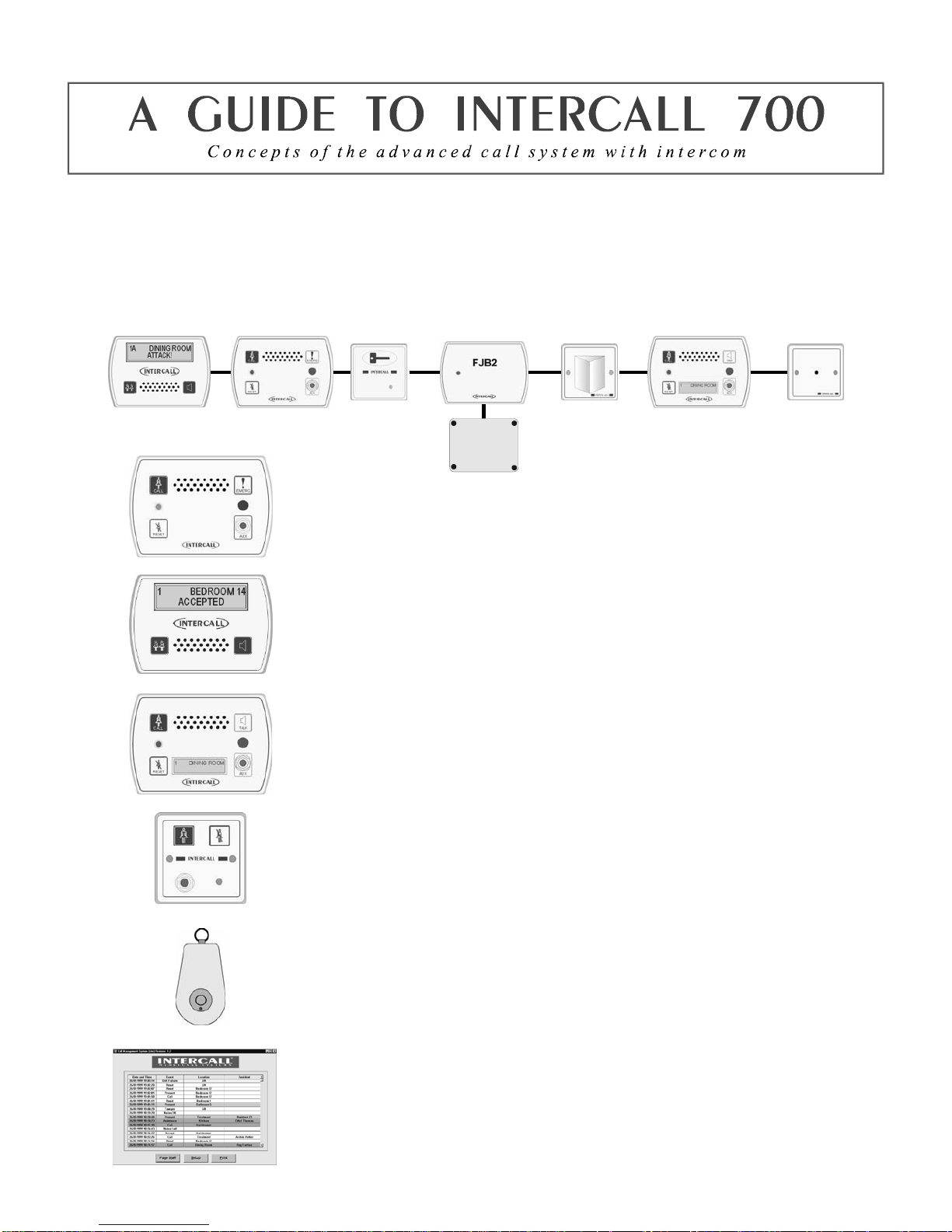
The INTERCALL 700 is the latest innovation in the Intercall range of advanced call systems. The system boasts all
the features of the Intercall 600 system together with hands free two way speech facilities between all audio units. All
room call points have an integral infra red receiver which allows a call to be generated away from the call point without
the need for trailing wires. Using an infra red trigger TIR4, it is possible to identify the calling resident together with
their location which can be used to route the call to specific members of staff. The system is fully addressable and only
requires connection to a common 12v network cable. The system is configured using a PC compatible computer or
similar & may be programmed on or off site as required.
L752 Audio Call Point.
An L752 is required for every individual audio call location on the system. It features 7
levels of call, hands free two way intercom, integral infra red receiver, audio page
facility, re-assurance LED & ‘call waiting’ sounder. The industry standard jack socket
will accept a host of triggering devices. The unit may be flush or surface mounted using
the Intercall BB1 backbox. See page 47
L758 Audio Display Unit.
Audio display units are generally located throughout the establishment and provide
description of the call type, location and identity of caller together with sounding the
integral alarm. It features 2 line back-lit display, multi function audible alarm, two way
intercom facility and audio page facility to all other displays and to all members of staff
present within a residents bedroom. see page 44
L762 Call/Display Unit
The L762 combines the features of the speech call point with a built in display. When in
staff present mode the unit will display all calls on the system in full alphanumeric text,
enabling staff to see & speak to other callers elsewhere on the system without having to
leave their patient. see page 48
L722 Non Audio Call Point.
The L722 Call Point contains identical features to the audio call point described above
without the intercom. Options which must be specified when ordering include:
emergency call only & non-latching operation for telephone ring detectors etc.
TIR4 Infra Red Trigger.
The infra red trigger is worn by residents and allows access to the call system at all times.
It will trigger any Intercall 700 series call point within range and can be configured to
generate different levels of call. Each trigger is assigned a unique number which may be
programmed into the system to identify the calling resident by name. see page 51
Intercall CMS Lite Software.
With the addition of the powerful Call Management Software, the Intercall 600/700
system becomes the complete solution to resident care. Running on any PC compatible
computer under Windows™ 2000/XP, it provides residents database, management
reporting and system control functions, in addition, the PC can be connected to a pager
transmitter and manage calls to staff alphanumeric pagers. see page 50

Intercall 600/700 Installation & Operation Guide Issue 4.27 Page 6 of 78
All INTERCALL systems can be enhanced with the use of accessories which allows the system to be used by patients
with virtually any level of disability. The following list details a few of the most popular accessories with their
application and part numbers. In addition to the standard range of accessories, we also manufacture bespoke accessories
to suit a particular requirement, please contact your supplier for more information.
NP2 & NP4 Pear Leads.
Our attractively styled pear leads allow access to the call system when residents are
away from the call point. The lead is available in 2Metre and 4 Metre lengths and the
right angle jack plug means that the plug is less likely to be damaged by furniture
movement. All pear leads are fitted with a clip fastener, which allows the unit to be
attached to clothing or bed sheets if required.
S2 Water Resistant Air Switches.
For bathroom / shower applications, the S2 Air Switch is ideal, being totally sealed
and safe as it uses air to trigger the call. The unit is supplied with 2metres of air pipe
which is then plugged into the front of any Intercall call point. The unit is fitted with a
clip fastener, which allows the unit to be attached to clothing or bed sheets if required.
All call points generate a standard call should the pear lead be removed from the jack
socket.
PS1 Plug In Pull Cord.
The PS1 converts a normal call point into a unit which may be activated by pull
string. The unit plugs into the jack socket and has a 30cm cord terminated with a
‘pull’ which allows the call point to be activated by simply pulling gently on the
‘pull’. This is ideal in toilets where a ceiling pull switch has not been fitted or where
is it out of reach.
PM1 Pressure Mat.
The PM1 is a standard pressure mat which plugs into the call point jack socket and
activates a standard call when pressure is applied to the mat. The unit should be
placed under a mat or carpet as it is not designed to be walked on directly. The unit
comes supplied with a four metre lead terminated with a right angle jack plug. The
surface area of the mat measures 300 x 600 mm.
BC1 Breath Switch.
The breath switch allows even the most severely handicapped access to the call
system. It operates in a similar way to the pear leads and air switches, generating a
standard call, and plugs into the jack on all call points. It is supplied with detachable
mouth - pieces, which may be sterilised.
TIR4 Infra Red Trigger.
The TIR4 allows a call point to be activated remotely, and has the advantage of
triggering a local call anywhere in the home (Infra Red Call Points only). This enables
carers to identify the location of the resident instantly. Competitors’ radio signals pass
through walls so while it is possible to know who requires assistance it is not possible
to pinpoint their exact location from the call system. The TIR4 requires infra red call
points to receive the signals, these are available on the Intercall 600 and 700 systems.
Using the TIR4 with an Intercall 700 system, it is possible to identify the calling
resident and call location.

Intercall 600/700 Installation & Operation Guide Issue 4.27 Page 7 of 78
Ordering Information
L617 600 Series Master Power Supply Unit.
L628 600 Series LCD Display Unit. (See Note 3)
L622 600 Series Standard Call Point.
L622M 600 Series Call Point with magnetic reset. (See Note 2)
L717 600/700 Series Master Power Supply Unit.
L752 700 Series Call Point with IR receiver and intercom facility. (See Note 3)
L762 700 Series Call/Display Unit as L752 with LCD unit. (See Note 3)
L758 700 Series LCD Display Unit with intercom facility. (See Note 3)
L768 700 Series Room Communicator.
L748 700 Series Corridor LED Display with 100mm characters.
L722 600/700 Series Non Audio Call Point with integral infra red receiver.
L732 600/700 Series Non Audio Call Point with integral infra red receiver.
L733 600/700 Series Door Monitoring & Access Control
L746 600/700 Series Two Colour Group Overdoor Light
L746S 600/700 Series Two Colour Group Overdoor Light with sounder
L737 500/600/700 Series Universal Booster Power Supply
L747 600/700 Series Universal Interface. (Operates with DPU414 or RFTX)
L714 600/700 Series Remote Sounder and relay output board
Optional Accessories
CS1 Ceiling Pull Switch with twin LED’s
LBAT 12V 1.9Ah Battery for Power Supplies (L617/L717/L737)
LIMKIT 600 / 700 Series System Configuration Kit including software.
CMSL CMS Lite Call Management Software for Intercall 600/700 Windows 2000/XP
SW1 Day / Night Switch - Connects to L617/L717
TIR4 Pendant Infra Red Trigger (Used with L722/L752/L762)
RFTX Scope Paging Transmitter & 1 Pager (Also Requires L747) (See Note 1 & 2)
RAP Additional Alphanumeric Pager for above (See Note 1)
DPU414 Thermal Printer to operate with L747
AD1 Adapter Plate (single gang plate to fit double gang box) (white)
AD3 Adapter Plate horizontal double to Pull switch (white)
LPR Thermal Printer Paper for obsolete DPU40 Printer
LPR2 Thermal Printer Paper for DPU414 Printer
M1 Door Contact Reed Switch (NO / NC)
NP2 Styled 2 Metre Pear Push Lead
NP4 Styled 4 Metre Pear Push Lead
PM1 Pressure Mat (600 x 300mm) Plugs into call point jack socket
PS1 Plug in Pull Cord for Call Points
RB1 Relay Board
SCP Slave Call Point (No electronics requires connection to call point)
SRP Slave Reset/Presence Point (For use with L732 Call Point)
S2 Soft Touch Air Switch with 3m of air pipe.
PIR1 Passive Infra Red Detector (See Note 2)
FJB2 Fused Junction Board
BB1 Surface Mounting Backbox for Intercall styled units
NOTES: 1 – SPECIAL PROGRAMMING REQUIRED – PLEASE CONTACT THE SALES OFFICE FOR MORE INFORMATION, 2 – SPECIAL
ORDER NON STOCK ITEM – PLEASE CONTACT THE SALES OFFICE FOR AVAILABILITY, 3 – REQUIRES INTERCALL BB1
BACKBOX FOR SURFACE MOUNTING – FLUSH MOUNTS INTO STANDARD DOUBLE GANG BACKBOX. ©1999 Lismore Instruments
Limited
Intercall 600/700 Installation & Operation Guide Issue 4.27 Page 8 of 78
Obsolete Order Codes with Replacements
OBSOLETE ORDER CODE / PRODUCT AVAILABLE EQUIVALENT
L607 600 Series Printer Interface L747 600/700 Series Universal Interface
L707 700 Series Printer Interface L747 600/700 Series Universal Interface
L627 600 Series Pager Interface L747 600/700 Series Universal Interface
L727 700 Series Pager Interface L747 600/700 Series Universal Interface
L616 600 Series Overdoor Light L746 600/700 Series Overdoor Light
L626 600 Series Group Overdoor Light L746 600/700 Series Overdoor Light
L716 600/700 Series Overdoor Light L746 600/700 Series Overdoor Light
L726 600/700 Series Group Overdoor Light L746 600/700 Series Overdoor Light
L726S 600/700 Series Overdoor Light + Sounder L746S 600/700 Series Overdoor Light + sounder
L618 600 Series LCD Display Unit L628 600 Series Display Unit (BB1 Backbox required when
upgrading surface mounted L618 unit)
PCPC1 600 Series Programming Software & Lead LIMKIT 600 / 700 Series System Configuration Kit including
software.
L722DK 600/700 Door Monitoring Point L733 600/700 Door Monitor & Access Control Point
AN133 600/700 Non Latching Module L634 Network Input/Output Module
L622_AN134 600/700 Remote Reset Call Point L634 Network Input/Output Module
L622_AN121 Call Point with Emergency Input L622_AN310 Call Point with extended inputs and outputs
AN Order Codes
Some items are available to suit particular applications and call points are available with alternative software to perform
specialist functions. The most common AN order codes are described below
L622 AN121 L622 Call point with additional terminals for emergency call from the X2 trigger input
L752 AN121 L752 Call point modified to generate emergency call from the X trigger input
Getting In touch with Intercall Nursecall Systems
UK Technical Support Telephone 0870 870 4660
Export Department Telephone +44 1403 713240
Fax +44 (0)1403 713141
Or visit: www.intercall.co.uk
This manual is updated regularly and copies may be downloaded in
Adobe® Acrobat® format from the website shown above.
Intercall 600/700 Installation & Operation Guide Issue 4.27 Page 9 of 78
Intercall 600 User Guide.
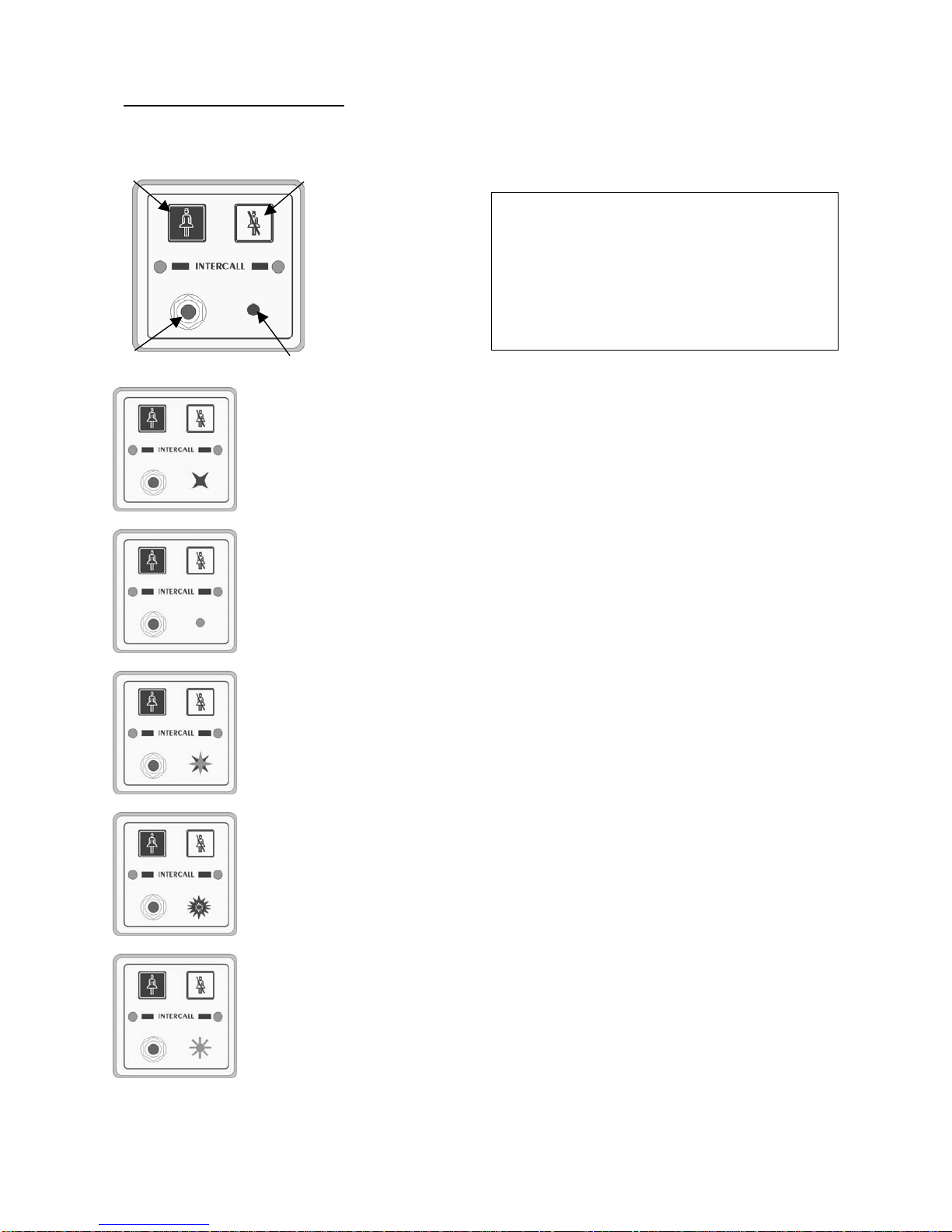
Layout of the Intercall 622 and 722 Non Audio Call Point.
Making a standard call.
A standard call can be generated by any of the following:
• Pressing the Call button on the call point.
• Activation of the pear lead (or other device) plugged into the Jack socket.
• Operation of a ceiling pull switch wired to the call point.
• Un-plugging the pear lead from the Jack socket.
To confirm a standard call is active, the Re-assurance light will flash red one per second.
Staff Present Mode*.
When members of staff enter a room, they must press the Reset button on the call point. The
call point is now in ‘Staff Present’ mode and the Re-assurance light will show a constant green.
Other members of staff can now locate them, by pressing the ‘Show Staff’ button on any display
unit. When they leave the room, they should press the Reset button again, this tells the system
they are no longer in the room & the Re-assurance light is off.
Staff Assistance Call*.
Staff assistance call can only be generated when the call point is in staff present mode and the
Re-assurance light showing constant green. Pressing the Call button will generate an
assistance call and the Re-assurance light will alternate red, then green, once a second to
confirm this action. To cancel the assistance call, press the Reset Button once. The call point is
now in staff present mode with the Re-assurance light showing constant green. To cancel the
staff present, press the Reset Button again until the Re-assurance light is off.
Staff Emergency/Crash Call.
Staff emergency call can be generated at any time by pressing the Call Button and the Reset
Button simultaneously (or pressing the Emergency Button). To confirm this action the Re-
assurance light will showing a rapid red flashing light. To cancel the emergency call, press the
Reset Button once, the call point is now in staff present mode with the Re-assurance light
showing constant green. To cancel the staff present mode, press the Reset Button again until the
Re-assurance light is off.
Call Accepted.
To avoid several members of staff from responding to a single call, calls may be accepted from
any display unit. To accept a call, wait until the call you wish to accept is on the top line of the
display and press the Accept Button. The call point re-assurance light will flash green to let
the resident know that staff are on their way. The call point will return to the calling condition if
the call point is not reset within a pre-set time period. Only standard calls and assistance calls
can be accepted.
* Features highlighted in this way, may be disabled by the commissioning engineer.
Intercall 600 Call levels and what they mean.
Call – Standard patient call
Assistance – Staff requiring assistance.
Emergency – Staff requiring urgent assistance.
Present – A member of staff is in the room.
Visit – A member of staff has accepted the call at the
display and is on their way to the resident.
nCall button.
oReset button.
pRe-assurance light.
qJack socket.
no
qp

Intercall 600/700 Installation & Operation Guide Issue 4.27 Page 10 of 78
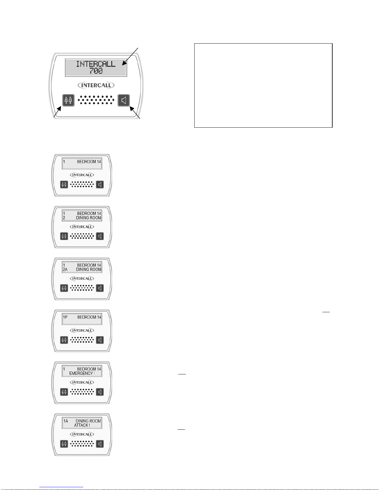
Using Intercall 600 Display Units.
nTwo line LCD display. oShow staff button. pAccept call button.
Standard Call.
A standard call will make a short uninterrupted tone, which repeats every 2 seconds.
The number shown on the left identifies the queue position, where the lowest number is
the oldest call. The right hand side of the display shows the call location. In the example
to the left, there is a call from “BEDROOM 24”.
More than one Call.
When more that one call is active, the calls are scrolled on the display with their
respective queue position.. On the example shown to the left, we have two active calls
“BEDROOM 24” is the oldest call and is in queue position 1. The call from “DINING
ROOM” is more recent and is given queue position 2.
Assistance Call*.
An assistance call will make two short tones which are repeated every two seconds. On
the illustration to the left, there is a standard call from Bedroom 14 and an assistance
call from the Dining Room. The ‘A’ after the call number identifies the call as an
assistance call.
Accepting a calling resident. (Accept Call/Visit)
To prevent several members of staff from responding to the same call, calls are
‘accepted’ at the display units. To accept a call, simply wait until the call you wish to
accept is shown on the top line of the display, then press the Accept Call button. It is
only possible to accept Standard and Assistance calls shown above.
Emergency Call.
An emergency call will make a fast series short tones which are repeated continuously.
On the illustration to the left, the word ‘EMERGENCY’ indicates the urgency of the
call. The accept facility is not available on emergency calls and the staff must attend the
room to reset. When an ‘emergency’ call is active, all other calls are held in memory
but only displayed when the emergency call is reset.
Locating other members of staff.
To locate other members of staff either in residents rooms or on their way to respond to
calls, simply press and hold the Show Staff button on any display panel. On the
illustration to the left, a member of staff is present in Bedroom 14, indicated by the
small ‘P’ and a member of staff has accepted and is visiting the call from the Lounge,
indicated by the small ‘V’. Numbering of ‘Visit’ and ‘Nurse Present’ events is the same
as standard and assistance calls.
Intercall 600 Call levels and what they mean.
Call – Standard patient call
Assistance – Staff requiring assistance.
Emergency – Staff requiring urgent assistance.
Present – A member of staff is in the room.
Visit – A member of staff has accepted the call at the
display and is on their way to the resident.
op
n

Intercall 600/700 Installation & Operation Guide Issue 4.27 Page 11 of 78
Intercall 700 User Guide.
Layout of the Intercall 752 Audio Call Point.
Making a standard call.
A standard call can be generated by any of the following:
• Pressing the Call button on the call point.
• Operation of the pear push lead (or other device) plugged into the Jack socket.
• Operation of a ceiling pull switch wired to the call point.
• Un-plugging the pear lead from the Jack socket.
• Operation of a radio or infra red pendant.
To confirm a standard call is active, the Re-assurance light will slowly flash red.
Priority Call*
A Standard call, which has remained active for a pre-set time period will automatically
convert to Priority Call and the Re-assurance light will flash rapidly.
Staff Present Mode*.
When members of staff enter a room, they must press the Reset button on the call
point. The call point is now in ‘Staff Present’ mode and the Re-assurance light will
show a constant green. Other members of staff can now locate and communicate to this
room. When they leave the room, they should press the Reset button again, this tells
the system they are no longer in the room & the Re-assurance light is off.
Staff Assistance Call*.
Staff assistance call can only be generated when the call point is in staff present mode
and the Re-assurance light showing constant green. Pressing the Call button will
generate an assistance call and the Re-assurance light will show red, then green once a
second to confirm this action. To cancel the assistance call, press the Reset Button
once. The call point is now in staff present mode with the Re-assurance light showing
constant green. To cancel the staff present, press the Reset Button again until the Re-
assurance light is off.
Staff Emergency/Crash Call.
Staff emergency call can be generated at any time by pressing the Call Button and the
Reset Button simultaneously (or pressing the Emergency Button). To confirm this
action the Re-assurance light will showing a rapid red flashing light. To cancel the
emergency call, press the Reset Button once, the call point is now in staff present mode
with the Re-assurance light showing constant green. To cancel the staff present mode,
press the Reset Button again until the Re-assurance light is off.
Staff Attack Calls.
Staff attack calls can only be generated from an infra red trigger remote from the call point. Attack level calls are
indicated by a very rapid red flash on the Re-assurance light and can only be reset with a ‘reset’ infra red trigger, or by
a Guardian display when used with a combined Intercall 700 / Guardian system.
Paging other members of staff*.
Locating and communicating with other members of staff is simplicity with the Intercall 700 system. Simply press and
hold the Reset button and you can page to all other Displays and Call points in Staff Present mode.
Intercall 700 Call levels and what they mean.
Call – Standard patient call
Priority – Standard patient call which has remained
unanswered for a period of time.
Assistance – Staff requiring assistance.
Emergency – Staff requiring urgent assistance.
Attack – Staff under threat & require urgent assistance.
Present – A member of staff is in the room.
Visit – A member of staff has accepted the call at the
display and is on their way to the resident. If the intercom
facility has been used, this will be logged on the printer.
n
p
oq
r
nCall button.
oReset button.
pRe-assurance light.
qJack socket.
rEmergency button.
Intercall 600/700 Installation & Operation Guide Issue 4.27 Page 12 of 78
Layout of the Intercall 758 Audio Display Unit.
nTwo line LCD display. oShow staff button. pAccept call / Intercom button.
Standard Call.
A standard call will make a short uninterrupted tone, which repeats every 2 seconds. The
number shown on the left identifies the queue position, where the lowest number is the
oldest call. The right hand side of the display shows the call location. In the example,
there is a call from “BEDROOM 24”.
More than one Call.
When more that one call is active, the calls are scrolled on the display with their
respective queue position. On the example shown to the left, we have two active calls
“BEDROOM 24” is the oldest call and is in queue position 1. The call from “DINING
ROOM” is more recent and is given queue position 2
Assistance Call*.
An assistance call will make two short tones which are repeated every 2 seconds. On the
illustration to the left, there is a standard call from Bedroom 14 and an assistance call
from the Dining Room.
Priority Call*.
If a standard call remains un-answered, it automatically converts to a Priority Call. A
Priority call is indicated with a letter ‘P’ after the call number. The intercom facility is not
available on priority calls and the staff must attend the room to reset. When a priority call
is active, all standard and assistance calls are held in memory but only displayed when the
priority is reset.
Emergency Call.
An emergency call will make a fast series short tones, which are repeated continuously.
On the illustration to the left, the word ‘EMERGENCY’ indicates the urgency of the call.
The intercom facility is not available on emergency calls and the staff must attend the
room to reset. When an ‘attack’ or ‘emergency’ call is active, all other calls are held in
memory but only displayed when the emergency call is reset.
Attack Call.
An attack call will make a fast series short tones, which are repeated continuously. On the
lower line of the LCD, the word ‘ATTACK’ is displayed similar to an emergency call.
The intercom facility is not available on emergency calls and the call can only be reset
with an infra red ‘reset’ trigger or using a Guardian display unit. When an ATTACK or
EMERGENCY call is active, all other calls are held in memory but only displayed when
the emergency call is reset.
n
p
o
Intercall 700 Call levels and what they mean.
Call – Standard patient call
Priority – Standard patient call which has remained
unanswered for a period of time.
Assistance – Staff requiring assistance.
Emergency – Staff requiring urgent assistance.
Attack – Staff under threat & require urgent assistance.
Present – A member of staff is in the room.
Visit – A member of staff has accepted the call at the
display and is on their way to the resident.

Intercall 600/700 Installation & Operation Guide Issue 4.27 Page 13 of 78
Accepting a call. (Accepting a non-speech call)
To prevent several members of staff from responding to the same call, calls are
‘accepted’ at the display units. To accept a call, simply wait until the call you wish to
accept is shown on the top line of the display, and press the Accept Call button. It is only
possible to accept Standard and Assistance calls shown previously. If you are accepting a
non-speech call point (such as a toilet or door point) then the call will be removed from
the display and the sounder silenced for a pre-set period of time.
Accepting a call and speaking to a calling resident.
To accept and speak to a resident, the procedure is the same as ‘accepting a call’ above.
Wait until the call you call you wish to speak to is shown on the top line of the display,
press & release the Accept Call button. Once the word “speech open” appears, you will
be able to hear the caller. Press and hold the Accept Call button when talking to the
resident. Once the conversation is complete, press the Show Staff button once to close
the intercom. (The speech channel will close after 60 seconds automatically)
Speech Busy.
To indicate to all other users that the speech channel is in use, ‘Speech Busy’ appears on
the lower line of all other displays on the system and this is shown to the left. On all other
displays, new calls will be shown using the top line of the LCD only and calls may be
accepted (as non-speech calls) but the intercom facility will not activate.
Locating other members of staff.
To locate other members of staff, press and hold the Show Staff button on any display
panel. On the left, a member of staff is present in Bedroom 14, indicated by the small ‘p’
and a member of staff is dealing with the call from the Lounge, indicated by the small ‘v’.
Paging all other members of staff.
To page all staff, simply press and hold the Talk button and speak to all other displays
and call points in staff present mode. This is only possible when no calls are active on the
system and is not possible when ‘Speech Busy’ is displayed on the lower line of the
LCD.
Intercall 600/700 Installation & Operation Guide Issue 4.27 Page 14 of 78
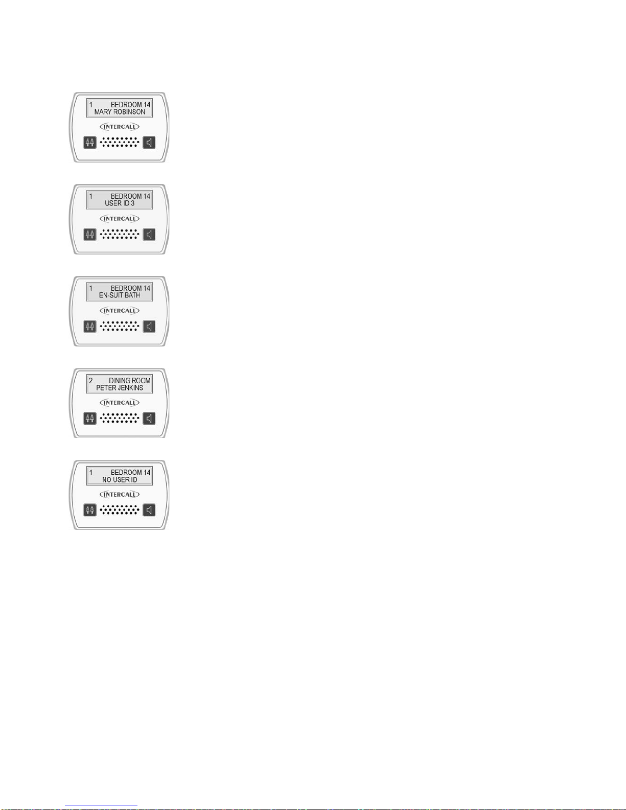
User ID on the Intercall 700 System.
How the displays show who is calling*.
With the Intercall 700 system, it is possible to display the residents name, was well as
their location when calling. We call this feature ‘User ID’. In order to register their name
on the system, the resident must trigger the call point with an infra red trigger assigned to
their name. All Intercall 700 Call Points are fitted with an infra red receiver which picks
up these signals.
Standard Calls/Assistance Calls/Priority Calls.
The main difference when the User ID is enabled, is that both lines of the LCD are used
for each call. On the top line, the location is displayed as previously and on the lower
line, the User ID is displayed. Above left, is a standard call from ‘Bedroom 14’ activated
by the trigger allocated to ‘Mary Robinson’. To the left shows the factory default ‘User
No’ rather than the residents name.
Secondary Descriptions*.
Four User ID’s are reserved as System User ID, these allow common descriptions to be
allocated to other calling devices, connected to the call point. For example, a ceiling pull
switch in an en-suit bathroom may be given the secondary description “EN-SUIT BATH”
This will be combined with the room description when the switch is activated to produce
“BEROOM 14 EN-SUIT BATH” as shown on the left.
More than one call active.
When more than one call is active, the calls are scrolled on the LCD display as normal
but you can only see one call at any time. Each call is shown with the corresponding
Caller ID. On the right we have a second call activated, with call number ‘2’ and this
time from ‘Peter Jenkins’ in the ‘Dining Room’.
No User ID.
If a call point is not triggered from the infra red trigger, it is not possible to establish
which resident activated the call point. When this occurs ,the lower line of the display
reports ‘No User ID’ as shown on the left. This feature can be disabled at the
commissioning stage.

Intercall 600/700 Installation & Operation Guide Issue 4.27 Page 15 of 78
Using the L768 Room Communicator.
The L768 Room Communicator allows the intercom speech path to be initiated to a Call Point without the Call Point
having called first. The unit is very simple to use with the desired room selected using the rotary control on the front
panel. General announcements (such as lunch times etc) can also be made from the unit and these are sent into all
bedrooms. The L768 must be used in conjunction with L758 displays to show and sound for calls from the rooms.
To call and speak to a room.
Turning the SELECT control (Shown on the left) clockwise or anticlockwise will scroll
through all available call points on the system. You may contact any call point which is
not currently calling. Rooms can be contacted regardless of other system activity,
providing the speech channel is not in use. While the rooms are being contacted, the call
point buttons are inactive.
Selecting the desired room.
Turn the Select control until the desired room is showing on the top line of the display. In
the example shown on the left BEDROOM 21 is being selected.
The privacy bleep.
With the desired room showing on the top line, press and release the TALK button as
shown on the left. There will be a small delay while the room is contacted before the
privacy bleep is sounded at the call point and at the Room Communicator. While the
room is contacted, the screen will show PLEASE WAIT on the lower line of the display.
Opening the speech channel.
After the privacy bleep has sounded, the intercom channel will be open and the call point
will be able to speak to the Room Communicator. Press and hold the TALK button while
speaking to the room and release to allow the room to speak. While the speech channel is
open the words “Speech Open” will be showing on the lower line of the display.
Closing the speech channel.
When the conversation is complete, the intercom may be closed by pressing the SELECT
button once. This will reset the unit and close the intercom channel.
Selecting another room.
Once the speech channel has been closed and the room is again showing on the top line
of the display, another room can be selected using the SELECT control as previously
described. Alternatively, if the SELECT control is not operated for 10 seconds, the unit
will return to the default text (Intercall 700)
Broadcast or Tannoy messages to all rooms.
The room Communicator can also be used to send common messages to all Call Points.
Call Points can be contacted regardless of other system activity, providing the speech
channel is not in use.
Selecting tannoy.
Turning the SELECT control (Shown on the left) clockwise or anticlockwise will scroll
through the rooms on the system. Use this method until TANNOY ALL ROOMS is
shown on the LCD display.
Using the Tannoy.
With TANNOY ALL ROOMS showing on the display, press and HOLD DOWN the
TALK button. There will be a small delay while the rooms are contacted before the
privacy bleep is sounded in the room and at the Room Communicator. While the room is
being contacted, the screen will show PLEASE WAIT on the lower line of the display.
Now make the announcement and release the TALK button. It is not possible for the
rooms to speak back to the Room Controller in this mode. While the rooms are being
contacted, the call point buttons are inactive.

Intercall 600/700 Installation & Operation Guide Issue 4.27 Page 16 of 78
Call/Display Unit.
Tdhe L762 Call/Display Unit combines the features of the L752 Call Point and L758 LCD
Display unit. Calls are generated in the same way as with the Audio Call Point discussed
previously, with the exception that there is no separate emergency button. (Emergency calls
are generated by pressing both call and reset buttons simultaneously) The LCD display is
enabled when the call point is in ‘Staff Present Mode’ and operates in a similar way to the
LCD Display Unit also described previously.
Normally, when no call is active on the system, the LCD will show the programmed default
text and the factory default is ‘Intercall 700’. If an Emergency or Attack call is active, the
LCD display will show this call, but the sounder will not operate unless the call point is in
‘Staff Present’ mode.
How the displays show faults on the system.
The system is continuously monitored and should a system fault occur, the lower line of the
LCD will read System Fault and this is accompanied by an audible alarm, which informs of
problems without becoming intrusive.
Overdoor Lights.
Overdoor lights are an optional item generally located outside the room to relay the status
of the call point within the room. The unit is fitted with twin red/green LED’s which mimic
the re-assurance LED on the call points.
Overdoor Light Call Patterns.
Call – Slow Flashing Red
Priority – Fast Flashing Red
Assistance – Alternating Red / Green flash
Emergency – Rapid Red Flashing.
Attack – Very Rapid Red Flashing.
Present – Continuous Greeen Indication.
Call Accepted / Spoken – Slow Green Flashing
Door Monitoring and Access Control Points.
Generally used to monitor fire doors and main entrances for unauthorised entry or exit.
Token allows door to be opened by authorised personnel without sounding the alarm and
isolated to allow the door to be left open if required. See page33
Slave Call Points.
Similar to standard call points, these units are generally used in rooms with several beds.
The unit can only generate a standard call from the CALL button or jack socket. There is
no facility to reset and this must be done on the standard call point within the room.
Slave Reset/Present Points.
Similar to standard call points, these units are located by the door of the room or ward to
allow the staff to generate staff present indication and to reset the call away from the call
point. There is no call facility on this unit. See page 54
Remote Infra Red Trigger.
The TIR4 Infra Red Trigger may be used to make a call away from the call point without
trailing wires. All Intercall 700 call points are fitted with an infra red receiver as standard,
which will receive signals from the trigger within a typical 5 x 5 metre room. See page 51
Pear Leads.
Pear leads are used to trigger the any Intercall call point. They are available in 2metre and 4metre lengths terminated
with a 90 degree jack plug. There is a clip which may be used to secure the lead to bedding or residents clothing. The
unit features a wipe clean, soft touch switch which is easy activated with light finger pressure.
Intercall 600/700 Installation & Operation Guide Issue 4.27 Page 17 of 78
Installation Guide.
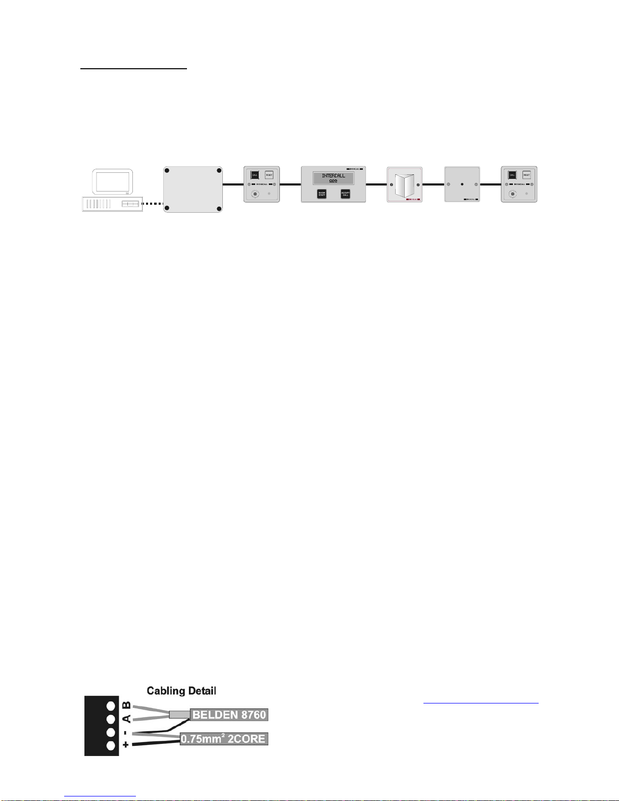
System Concepts.
Both the Intercall 600 and Intercall 700 systems are fully addressable and network devices only require a connection to
the common “Network” to operate. The Intercall 600 system uses a two core network for power and signals, while the
Intercall 700 audio system uses a four core network, one pair for power and signal and the other pair for audio. All
units are fitted with a positive (+) and negative (-) terminal and Intercall 700 audio devices have additional (a) and (b)
terminals for the audio pair.
‘Network Devices’ (Call Points, LCD Displays, Overdoor Lights etc) connect to the ‘Network’ which proves all power.
The system may be configured using a PC or Laptop Computer which connects to the L717 Power Supply.
As can be seen on page 3, several Intercall 600 and Intercall 700 network devices may be used on either systems. In
addition, it is not necessary to have the audio feature on an entire Intercall 700 system, for example L722 Non Audio
Call Points may be used within the bedrooms while Audio Call Points and Audio Displays are used elsewhere on the
system. To reduce audio interference and costs, we recommend that the network audio pair is only run to the parts of
the system where the audio feature is required.
As with all systems of this nature, the integrity of the network cabling is paramount to the performance and reliability
of the system. Excessive cable volt drop must be avoided and to achieve this we recommend the use of a heavier
“Spine” cable between Power Suppl(ies) and to Junction Units, then lighter “Spur” cables from the Junction units,
taking in the network devices. The network output from the power supply runs at 13.8V and the network devices will
operate down to 10 Volts permitting a 3.8v maximum volt drop along the network cables to the furthest device.
We only recommend the use of FJB units, which have fused outputs for the wiring of individual sections of the system.
Generally, one FJB would be located on each floor on wing of the establishment, with the Spine Cable connecting them
back to the Power Supply Units.
Understanding “Current Units”.
The amount of volt drop experienced in each length of cable depends on the size of the cable and the total amount of
current drawn by the network devices attached to it. To simplify the cable run calculations, we have given each network
device a ‘Current Unit’ value, which reflects the amount of current drawn by that unit. The following limits apply: 1.
The absolute maximum length of each spur from the FJB 2. The maximum number of ‘Current Units’ per spur
from the FJB. 3. The spine cable is also limited to a maximum length per system.
Network Cable for Intercall 600 and Intercall 700 Non speech Installations.
Use a 2 core non screened minimum 0.75mm2(24/0.2) cable for the network ‘Spine’ between the power supplies and
to the FJB’s and 4 or 6 core non-screened stranded security alarm cable 0.22mm2(7/0.2) for the network spur outputs
from the FJB.
Network Cables for Intercall 700 speech Installations.
We recommend 2 core non screened minimum 0.75mm2(24/0.2) and Belden 8760 for the network spine and Belden
8723 for the network spur outputs from the FJB.
Belden 8760 is a single pair cable, connect to the (A) and (B) terminals with the screen drain wire connected to (-
)and use 2 core the 0.75mm2non screened for the (+) and (-) connections.
Belden 8723 is a two pair individual screened cable. Use one pair for the (+) & (–) & one pair for the (A) & (B).
Connect the screen drain wire to the Network (–) terminal.
Belden cable (or equivalent) is available from
Commtech Communications www.commtechcomm.com
Phone +44(0)1254 232638 Fax +44(0)1254 301197
or other specialist suppliers.

Intercall 600/700 Installation & Operation Guide Issue 4.27 Page 18 of 78
Planning an Installation.
• Locate the L717 PSU/Controller in a central location of
the building and run “Spine” cable(s) to FJB and Booster
Power supply locations. We recommend one FJB/Booster
location per floor & the spine cable running between floors.
• Run a maximum of 4 cable spurs from the FJB’s each no
longer than 60 metres with a maximum of 25 current
units per spur. See the chart on the right for a “Current
Unit” rating for each network device.
• If the system requires more than 100 current units – split
the system with a Booster Power Supply.
• If the system requires more than 600 metres of network
cable (including the spine and all spurs) – split the system
with a Booster Power Supply.
• Each spine cable must be no longer than 80 metres from
Master Power Supply to furthest Booster Power Supply
(or FJB)
• All Booster Power Supply inputs must be connected to the Master Power Supply output. See page 33
• Avoid running Network cables alongside mains cables., fluorescent lights, electrical switch-gear, lift machinery
and motors and high voltage cables.
• Never use two cores within a cable used for other systems. Eg Fire Alarm, Telephones etc.
• There must be NO CONNECTION between the Network + or – and mains electrical earth.
• IMPORTANT The spur length limits assumes that units are located at regular intervals along the length of the cable
and that a maximum of 20% of the call points are calling at any one time. This limit can be increased by reducing the
length of spur or number of current units attached to the spur. Eg 40% of the units calling at any one time, max cable run
30 metres or maximum 12 current units per spur.
The following table shows the number of
‘Current Units’ for each piece of equipment
Device Description No of
Units
L622 Standard Call Point 1
L622M Magnetic Call Point 1
L733 Door Monitoring Point 1
L634 I/O Module 1
CS1 Ceiling Pull Switch 0
SCP Slave Call Point 0
L628 Larger LCD Display 4
L746 Overdoor Light 1
L746S Light + Sounder 3
L714 Remote Sounder 4
L747 System Interface 4
RB1 Relay Board 2
PIR1 Passive Infra Red Unit 1
L722 Infra Red Call Point 1.5
L752 Audio Call Point 2.5
L758 Audio Displays Unit 4
L762 Audio Call/Disp Unit 2.5
Ceiling Pull switches &
Slave Call point connect to
the call point only
Additional Spines to other
F
JB and Booster Units
PSU
BPS
Maximum of 25 Current Units Per Spur
Maximum len
g
th o
f
each s
p
ur 60 metres
Total amount of network cabling including spine and all
spurs must not exceed 600 Metres per power supply.
Maximum load per power supply: 100 current units
S
Spine Max length 80M

Intercall 600/700 Installation & Operation Guide Issue 4.27 Page 19 of 78
Replacing an existing System – using the existing wiring.
The INTERCALL system is ideally suited for the replacement of existing hard wired nursecall system, using the
existing cabling but please note the following considerations.
• Study and make notes about the existing system.
The most common problems occur when the old system is removed before the wiring is understood. We need to
identify two cores common to all parts of the system which are usually the supply lines. Look for legends on the printed
circuit boards (0v, GND, +12 + etc)
• Remove all parts of the old system from the wiring.
Another common problem is where parts of the old system are still connected, a remote sounder, bell or buzzer in
another part of the system.
• Make sure the old power supply is switched off and disconnected from the system.
Do not attempt to keep the old system running on the same cables as you are installing the new system, you are most
likely to damage both systems and delay completion.
• Beware of Multi-core cables.
Multi-core cable is often used on older systems where every call point requires an individual connection back to the
display panel. This cable must be 80 pair cable (160 cores) is quite common. If you are using multicore cable you
should only use two cores within the multi-core length. If this cable is too small to connect the amount of current units
required, then this cable should be replaced with a cable of the SPINE specification.
When using the existing cabling, normally there is one cable back from each call point. In this instance, we would
connect several call points cables together (to a maximum of 25 current units) and connect them to one single output of
the FJB. Once the existing cabling is connected, additional spurs can be run from the FJB for new extensions as shown
above.
Typical New Installation.
CP CP CP CP CP CP CP CP
CP
CP CP
CP CP CP CP CP CP CP CP
D
LCD
CP CP
DM
CP CP CP
CP CP CPCP CP CP
LCD
FJB
FJB
PSU
FJB
FJB
PSU
FJB
BPS
FJB
The above diagram shows the FJB1 in use
showing four spur outputs. Always locate the
FJB2 in a central location (extending the spine
to a central location if necessary) minimising the
length of the individual cable spurs.
On the right, we are showing two buildings with
the Spine cable running between floors and on the
three floor building, a Booster is located on the top
floor
Other manuals for 600
1
This manual suits for next models
1
Table of contents


