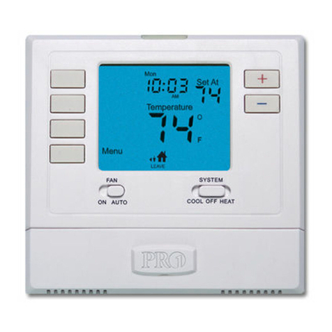
INTEREL EOS User manual

1 / 9© INTEREL 2021 - rev07
EOS
Installation
Manual

2 / 9© INTEREL 2021 - rev07
Required Installation Hardware
Included
Not included
Optional Installation Hardware
See property specic documentation for entry door and balcony/
window contact requirements.
Required Commissioning Software
The EOS Thermostat can be commissioned through the EOS
Installer mobile app available for download on the Apple App Store
(https://apps.apple.com/lb/app/eos-installer/id1533441613).
The requirements for the app are:
• Requires iOS 12.0 or later.
• User prole for eld technicians registered with INTEREL.
• Data connection (cellular or WiFi) at time of commissioning.
Required Tools
and Software
• (1) EOS Metal Wall Bracket
• (1) EOS thermostat
• (4) #6/32, 1”Phillips head counter sunk screws (US standard back box)
• (2) Flat head DIN965 A2 (BS standard back box)
• Philips head screwdriver
• Flat head screwdrivers small (2.5mm - 3/32”) large (3.5mm - 9/64”)
• Wire cutters / strippers
• Smartphone (Apple iPhone 7 or newer with iOS 12.0 or later)
Material: Stainless Steel 0.06” / 1.5 mm

3 / 9© INTEREL 2021 - rev07
Installation
Location
Select a location about 1.5m (5ft) above the oor and with
good air circulation at average temperature. Do not mount
the thermostat where it may be aected by:
• Drafts or dead spots behind doors or in corners
• Hot or cold air from ducts
• Radiant heat from sun or appliances
• Pipes or chimneys
• Unheated or uncooled areas behind the thermostat
• RF sources or transmitters
For accurate presence detection using the built-in PIR sen-
sor, consider the sensor’s view angle, range characteristics
and thermostat mounting position.
Mounting
The INTEREL EOS Thermostat is designed to be surface
mounted, and therefore can be installed in almost any sce-
nario found in a hotel guestroom. Typically, the EOS ther-
mostat will be mounted on a (4x4) double-gang junction
box. If mounted on a single-gang junction box, the 24 Vac
power or 100–277 Vac power and signal wires connecting
CN2 to the HVAC equipment must reside in the single-gang
box, and the low voltage signal wires connected to CN1 re-
side on the left side overlapping the wall area. A low voltage
mud ring, or low voltage caddy may be used for mounting
the 24V AC EOS Thermostat.
Before beginning work, ensure that the supply power
(24 Vac or 100-277 Vac) is turned o and secured. If an
existing thermostat is being replaced, remove the ther-
mostat and note the function of each wire if not already
documented. Position the EOS Metal Wall Bracket with
raised arrows pointing UP and mount it to the junction
box using the (4) provided screws. The installation area
behind the bracket must be at and free from debris to
allow the Metal Wall Bracket to sit at on the wall. Adjust
the bracket position to be level before fully tightening
the screws. Do not over tighten the screws, which may
result in a loose connection to the EOS Thermostat.
Remove the CN1 and CN2 connectors from the back of
the thermostat by prying them out gently with a at
head screwdriver. Then prepare the power and control
wiring coming from the HVAC equipment and connect
the appropriate wires to their respective terminals on
the CN1 and CN2 connectors (refer to the property and
HVAC equipment wiring diagrams).
Insert the CN1 and CN2 connectors back into EOS, veri-
fying that they are fully seated for a secure connection.
When mixed voltages are used on the CN1 and CN2
connectors, a voltage separator must be installed per
local electrical code regulations. Line voltage must re-
side in the right side of the junction box and low volt-
age must reside in the left side of the junction box.
Installation Instructions
CAUTION: Disconnect the power supply before installation to pre-
vent electrical shock or equipment damage. All wiring must comply
with local codes and ordinances.
• Read the instructions carefully. Failure to follow them could damage the product or create a hazard.
• Check the ratings given in the EOS datasheet and on the product to ensure the product is suitably rated
for the application.
• The installer must be a trained, experienced HVAC technician.
• After installation is complete, check product operation as indicated in the instructions.
1.
2.
3.

4 / 9© INTEREL 2021 - rev07
The thermostat slides downwards and locks onto the metal
mounting bracket utilizing the six hooks on the metal brack-
et. Position the thermostat just above the mounting bracket,
press towards the wall and slide it down, securing it to the
bracket. The thermostat will snap into place on the metal
wall bracket and feel securely fashioned if installed properly.
To lock the thermostat to the wall, use the large at head
screwdriver to turn the lock pawl on the bottom side of the
thermostat counterclockwise. Test the closure by gently lift-
ing the thermostat upwards.
Apply power to the EOS Thermostat by closing the applica-
ble supply breaker. Verify that the EOS Thermostat powers up.
The OLED display should show INTEREL and 3 dots.
Pinch the protective lm tab tab on the top right of the ther-
mostat display and pull straight out to slowly peel the lm.
Remove the lm slowly to reduce the risk of tearing it and
leaving residue on the thermostat display.
Do not Overtighten Screws
15-1000
Turn lock pawl
counterclockwise
to securely x it
4.
5.
6.
7.
Countersunk Screws (US)
6-32 1.5”Countersunk Machine Screws
Countersunk Screws (EU)
Din 965 A2 Machined Screws
or
EOS Thermostat
Metal Wall Bracket
Stainless Steel 1.5 mm (0.06”)

5 / 9© INTEREL 2021 - rev07
Electrical
Connections
Pin Signal Function
1 B Modbus Communications
2 A Modbus Communications
3AO2 Heat, Heat 1, Cool
4AO1 Cool, Cool 1, Fan
5 DIN3 Remote PIR
6 DIN2 Balcony/Window Contact
7 DIN1 Main Door Contact
8 DO1 Pilot Duty Contactor
9 GND Ground
10 V+ 12 Vdc
Pin Code Typical Function
1CNeutral
2 G Ground
3 ER System Power
4GH Fan High, Fan
5GM Fan Medium, Heat 1, Rev Valve
6 FR Fan Power
7 GL Fan Low, Cool 2
8 VR Valve Power
9 W Heat, Heat 2, Rev Valve
10 Y Cool, Cool 1, Heat 1
Pin Code Typical Function
1 C Neutral
2 G Ground
3ER System Power
4 GH Fan High, Fan
5 GM Fan Medium, Heat 1, Rev Valve
6 FR Fan Power
7GL Fan Low, Cool 2
8 VR Valve Power
9WHeat, Heat 2, Rev Valve
10 Y Cool, Cool 1, Heat 1
Low Voltage Signals
24 Vac power and HVAC signal 100–277 Vac power and HVAC signal
-1
B-
A-
A02-
A01-
DIN3-
DIN2-
DIN1-
DO1-
GND-
12V-
B-
A-
A02-
A01-
DIN3-
DIN2-
DIN1-
DO1-
GND-
12V-
-10
CN2
CN1
CN1 CN1
CN2 CN2
CN2
NOTE: Wiring schematics are generated together with the
quotation for each project. The quotation contains a link to
the correct wiring schematic.

6 / 9© INTEREL 2021 - rev07
UL Listing
This device meets UL 60730-2-9, CAN/CSA-E60730-9 Stan-
dard for Automatic Electrical Controls - Part 2-9: Particular
Requirements for Temperature Sensing Control.
Federal Communications Commission
(FCC)
FCCID:
802.11 (WIFI) 2AC7Z-ESPWROOM32
802.15 (BLE) SH6MDBT50Q
802.15.4 (ZigBee) SH6MDBT50Q
Changes or modications not expressly approved by INTEREL
could void the user’s authority to operate the equipment.
EN
This equipment has been tested and found to comply with
the limits for a Class A digital device, pursuant to Part 15
of the FCC Rules. These limits are designed to provide rea-
sonable protection against harmful interference when the
equipment is operated in a commercial environment. This
equipment generates, uses and can radiate radio frequency
energy and, if not installed and used in accordance with the
instruction manual, may cause harmful interference to radio
communications.
Operation of this equipment in a residential area is likely to
cause harmful interference in which case the user will be re-
quired to correct the interference at his own expense.
This device complies with FCC and IC radiation exposure
limits set forth for an uncontrolled environment. This device
should be installed and operated with minimum distance of
20cm between the radiator and your body. This device must
not be co-located or operating in conjunction with any other
antenna or transmitter.
This device complies with part 15 of the FCC Rules. Opera-
tion is subject to the following two conditions: (1)This device
may not cause harmful interference, and (2) this device must
accept any interference received, including interference that
may cause undesired operation.
FR
Tout changement ou modication n’ayant pas été expressé-
ment approuvé par INTEREL International, Inc. pourrait an-
nuler l’autorisation de l’utilisateur d’utiliser l’équipement.
Cet équipement a subi des tests prouvant sa conformité aux
limites prescrites pour les appareils numériques de classe B,
selon la partie 15 des règlements de la FCC. Ces limites ont
été conçues pour fournir une protection raisonnable contre
les interférences nuisibles lorsque l’appareil est utilisé dans
un environnement résidentiel. Cet équipement génère, uti-
lise et peut émettre de l’énergie radioélectrique et, s’il n’est
pas installé et utilisé conformément aux instructions, peut
causer des interférences nuisibles aux communications ra-
dio. Toutefois, il n’y a aucune garantie que ces interférenc-
es ne puissent survenir dans une installation donnée. Si cet
équipement cause des interférences nuisibles à la réception
de signaux de radio ou de télévision, ce qui peut être déter-
miné en l’éteignant et en l’allumant, l’utilisateur peut essayer
de corriger ces interférences par les mesures suivantes :
• Réorienter ou déplacer l’antenne réceptrice.
• Augmenter la distance entre l’équipement et le récep-
teur.
• Brancher l’équipement sur un circuit diérent de celui
sur lequel le récepteur est branché.
• Consulter le détaillant ou un technicien expérimenté en
radio/télévision pour de l’aide.
Cet équipement a subi des tests prouvant sa conformité aux
limites prescrites pour les appareils numériques de classe A,
selon la partie 15 des règlements de la FCC. Ces limites ont
été conçues pour fournir une protection raisonnable contre
les interférences nuisibles lorsque l’appareil est utilisé dans
un environnement commercial. Cet équipement génère, uti-
lise et peut émettre de l’énergie radioélectrique et, s’il n’est
Regulatory and
Compliance

7 / 9© INTEREL 2021 - rev07
pas installé et utilisé conformément aux instructions, peut
causer des interférences nuisibles aux communications ra-
dio. L’utilisation de cet équipement dans une zone résiden-
tielle est susceptible de causer des interférences nuisibles
auquel cas l’utilisateur sera tenu de corriger ces interférences
à ses propres frais
Cet équipement est conforme aux limites d’exposition aux
rayonnements FCC et IC établies pour un environnement
non contrôlé. Cet équipement doit être installé et utilisé avec
un minimum de 20cm de distance entre la source de ray-
onnement et votre corps. Cet appareil ne doivent pas être
placés à côté de ou fonctionner en conjonction avec toute
autre antenne ou transmetteur.
Industry Canada (IC)
EN
This device complies with Industry Canada licence-exempt
RSS standard(s). Operation is subject to the following two
conditions: (1) this device may not cause interference, and
(2) this device must accept any interference, including inter-
ference that may cause undesired operation of the device.
FR
Le présent appareil est conforme aux CNR d’Industrie Cana-
da applicables aux appareils radio exempts de licence. L’ex-
ploitation est autorisée aux deux conditions suivantes : (1)
l’appareil ne doit pas produire de brouillage, et (2) l’appareil
doit accepter tout brouillage radioélectrique subi, même si
le brouillage est susceptible d’en compromettre le
fonctionnement.
• Purpose of Control: Thermostat
• Construction Control: Independetly Mounted
• Type 1 Action
• Pollution Degree 2
• Impulse Voltage: 330 V
• For use with provided connectors only
General Information

8 / 9© INTEREL 2021 - rev07
• Always power o the system before cleaning.
• Always use an anti-static wristband or other professional grounding devices.
• Never spray cleaning uids directly onto components. Always spray the cleaner onto a soft cloth then wipe.
• Do not allow any cleaner to run or drip near circuit boards, or near seams on device casings.
• Never allow circuits or electronics to become damp or wet.
• Some cleaning solvents can damage components. In most cases, water will work just as well.
• Do not attempt to clean any electronic components such as circuit boards or wire connection terminals.
• Hands shall not be wet when plugging and unplugging exible cords and connected equipment.
• Avoid the use of alkaline solution to clean the glass. Do not spray solvent directly onto glass face.
• Always use a soft cloth to wipe the glass when using solvent cleaner.
Cleaning procedures
Cleaning control panels shall start by wiping o any dust or debris with a clean and
dry microber cloth. Avoid direct spraying of cleaning uids onto the control panels or
electrical wiring.

9 / 9© INTEREL 2021 - rev07
• Explosions can be caused when
electricity provides a source of ignition
for an explosive mixture in the
atmosphere.
• Fires are caused by overloading
a circuit or appliance or by current
owing through high resistance due to
faulty wiring, setting re to insulation
and surrounding materials.
• Electric shock/electrocution occurs
when current ows through the body
damaging the body.
• Electrical burns are caused by arc
blast or hot conductors.
• Indirect falls from ladders, scaolds, or
other walking and working surfaces.
General Precautions Electrical Hazards
• Disconnect any devices from RCU Bus and
de-energize power supply prior to installation.
Failure to abide by the installation and operating
instructions may result in re and other hazards
• Comply with the terminal
specications as approved in the device pinouts as
per datasheet and dened on approved wiring
schematics Modication of electrical leads or
improper termination than where it is supposed to
be connected can cause damage to the unit.
• Device terminations shall be legibly labeled or
marked to indicate its purpose.
• Always follow the correct input/output
connections to the device based on the approved
design.
• Device should not be terminated with any high
voltage wiring. Do not mix the use of low voltage
and high voltage cable in the backbox and/or
conduit to pull wires. Wire run for Glass Panels and
Thermostat should be separate from any lighting
or HVAC loads.
• Electrical wires entering boxes,
cabinets, or ttings must be protected from
abrasion.
• All devices and all associated test leads, cables,
power cords, and connectors shall be visually
inspected for external defects and damage before
the equipment is used.
Safety Precautions
Follow the safety guidelines below in all attempts to access the electrical wirings of
controlled circuits that are connected to the Room Control Units:
Table of contents
