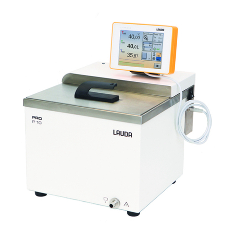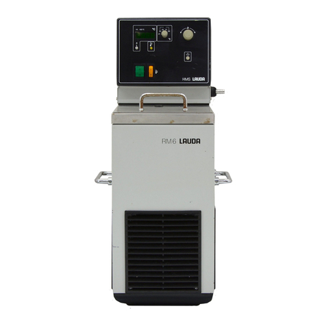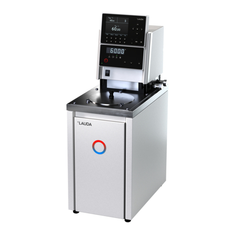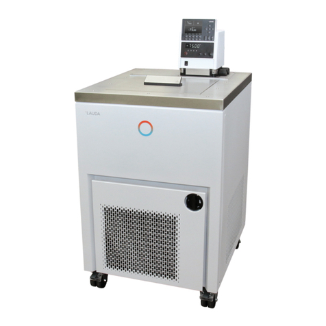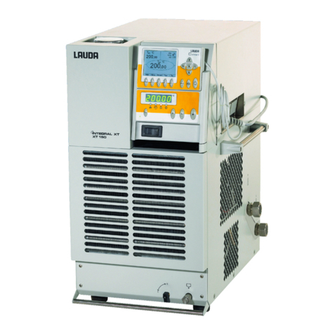
Proline Edition X heating thermostats
YACE0099 / 10/9/2018 Content 7
7.8.7 Entering the offset of the internal temperature probe ..................................................................... 54
7.8.8 Restoring the works setting of the internal temperature-probe offset............................................. 55
7.8.9 Entering the offset of the external temperature probe .................................................................... 56
7.8.10 Restoring the works setting of the external temperature-probe offset............................................ 57
7.9 GRAPHICAL DISPLAY OF TEMPERATURE MEASUREMENTS ............................................................................ 58
7.10 PROGRAMMER (PGM)........................................................................................................................... 60
7.10.1 Program example............................................................................................................................ 60
7.10.2 Selecting and starting the program (Start, Hold, Stop)................................................................... 62
7.10.3 Interrupting, continuing or terminating the program (Hold, Continue, Stop)................................... 63
7.10.4 Creating or modifying a program (Edit)........................................................................................... 64
7.10.5 Defining the number of program loops (Loops) .............................................................................. 68
7.10.6 Viewing the program sequence as a graph (Graph)....................................................................... 68
7.10.7 Obtaining information on a program (Info)...................................................................................... 69
7.11 RAMP FUNCTION ................................................................................................................................... 70
7.12 TIMER FUNCTION................................................................................................................................... 71
7.13 CONTROL PARAMETERS ........................................................................................................................ 73
7.13.1 Internal control variable (integral measurement probe).................................................................. 73
Proven settings for control parameters and pump (Internal control) ......................................................... 74
7.13.2 External control variable (External measurement probe) ............................................................... 75
Proven settings for control parameters and pump (external control): ....................................................... 76
Steps for setting the control parameters for external control..................................................................... 76
7.13.3 Internal and external control parameter sets .................................................................................. 78
7.14 ALARMS,WARNINGS AND ERRORS ........................................................................................................ 79
7.14.1 Overtemperature protection and checking...................................................................................... 79
7.14.2 Low-level alarm and low-level checking ......................................................................................... 81
7.14.3 High-level settings........................................................................................................................... 82
Master........................................................................................................................................................ 82
7.14.4 High-level warning or alarm ............................................................................................................ 83
7.14.5 Pump-motor supervision: Overload or blockage............................................................................. 84
7.14.6 Pump-motor supervision: Dry running ............................................................................................ 84
7.14.7 Fault list “Alarms and Warnings”..................................................................................................... 85
8INTERFACE MODULES............................................................................................................................... 88
8.1 INSTALLING MODULES ............................................................................................................................... 88
8.2 MENU STRUCTURE FOR ALL MODULES........................................................................................................ 89
8.3 RS-232/485 SERIAL INTERFACE ............................................................................................................... 90
8.3.1 Connecting cables and interface test RS-232 ................................................................................ 90
8.3.2 Protocol RS-232.............................................................................................................................. 91
8.3.3 Connecting cable RS-485............................................................................................................... 91
8.3.4 Protocol RS-485.............................................................................................................................. 92
8.3.5 Write commands (Data commands to the thermostat) ................................................................... 92
8.3.6 Read commands (Data requested from the thermostat) ................................................................ 93
8.3.7 Error messages............................................................................................................................... 95
8.3.8 Driver software for LABVIEW®....................................................................................................... 95
8.4 ANALOGUE MODULE.................................................................................................................................. 96
8.5 CONTACT MODULE.................................................................................................................................... 97
8.5.1 Contact module LRZ 915 with three inputs and three outputs ....................................................... 97
8.5.2 Namur-Contact module LRZ 914 with only one input and one output............................................ 98
9MAINTENANCE............................................................................................................................................ 99
9.1 CLEANING ................................................................................................................................................ 99
9.2 DEVICE STATUS........................................................................................................................................ 99
9.2.1 Interrogating the device type........................................................................................................... 99
9.2.2 Software Version............................................................................................................................. 99
9.2.3 Serial numbers................................................................................................................................ 99
9.2.4 Device data ................................................................................................................................... 100
9.2.5 Fault memory................................................................................................................................ 100
9.3 SERVICING,REPAIR AND DISPOSAL INFORMATION ..................................................................................... 101
