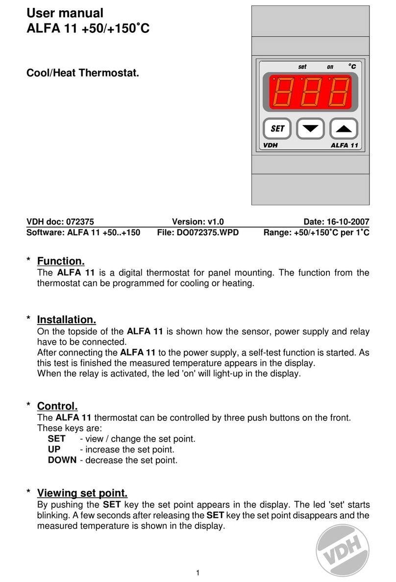
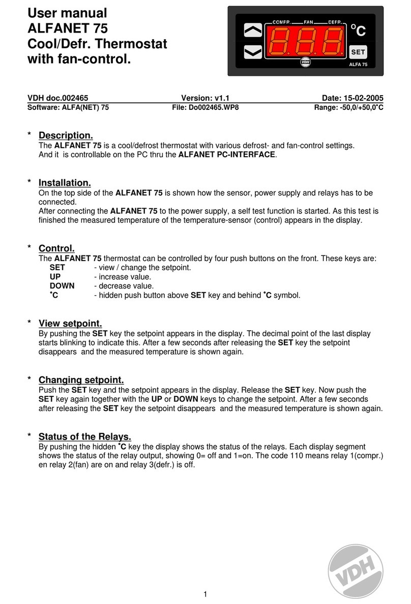
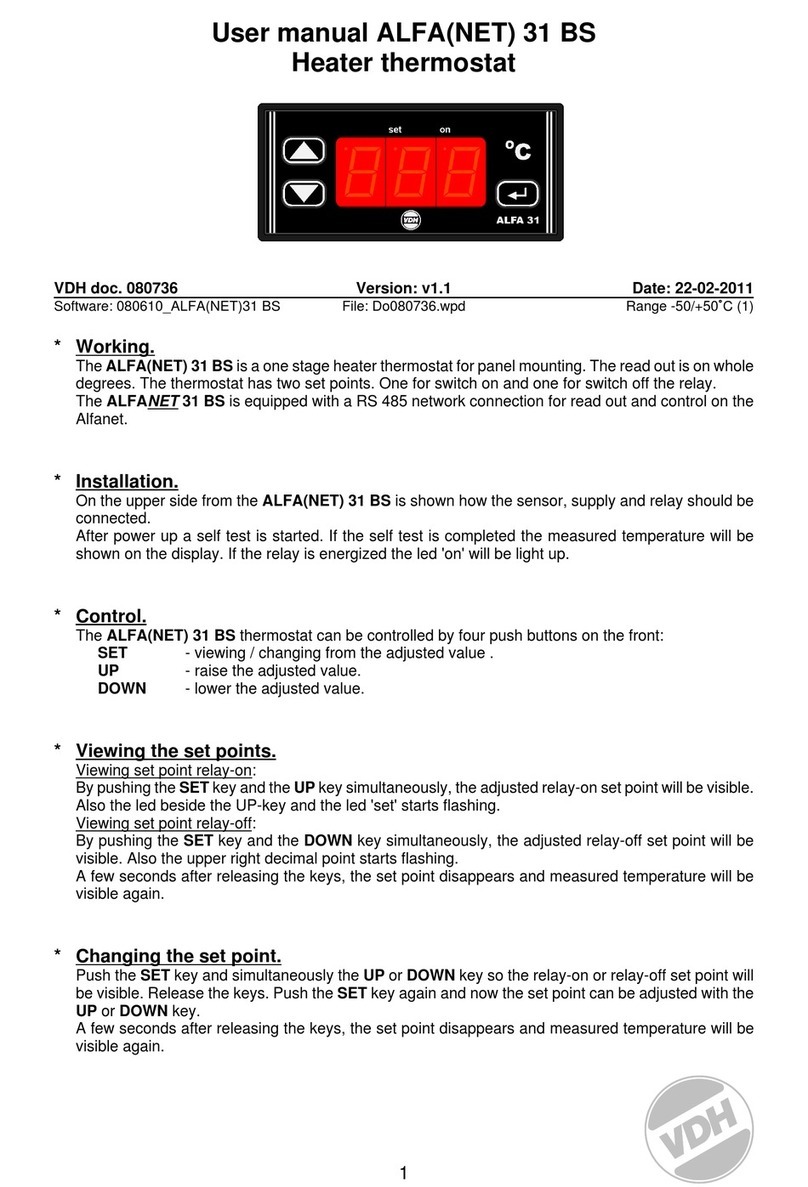
VDH Products MC 785T-DF User manual

MC 785T-DF
MC 785T-DF ALFANET
panel and wall mounting
Operating Manual
Description: MC 785T-DF (ALFANET) Thermostat Doc.no.: 042036
Type: MANUAL Number of pages: 20 Version: V1.1
File: Do042036 MC785T-DF v11 EN.wpd
Software: MC785T-DF Version: V2.00
By: AAD Date: 29-01-2014
VDH Products BV - Roden - Holland Signed: File: Doc'04

Operating Manual Document no.: 042036 Version: V1.1
MC 785T-DF Client: General Page: 2 of 20
Table of contents
1. Technical specifications ........................................................3
1.1 General ............................................................... 3
1.2 Front ..................................................................3
1.3 In- and outputs ..........................................................4
2. Functional specifications .......................................................4
3. Control of the thermostat .......................................................5
3.1 Read-out of the sensors. ..................................................5
3.2 Viewing and changing the day setpoint. ....................................... 5
3.3 Viewing and changing the night setpoint. .....................................5
3.4 Manual start of defrost. ...................................................5
3.5 Changing the defrost mode. ...............................................5
3.6 Operation of the fan control. ............................................... 5
3.7 Setting the clock. ........................................................5
3.8 Programming the DAY and NIGHT switching times. ............................. 6
3.9 Thermostat forced in the DAY stand. .........................................6
3.10 Thermostat forced in the NIGHT stand. .......................................6
3.11 Resetting the alarm. ...................................................... 6
3.12 Digital input. ............................................................6
4. Programming the internal settings ................................................6
4.1 Parameter table. ........................................................7
5. Operation of relay outputs .....................................................10
5.1 Operation of cooling and heating. .......................................... 10
5.2 Operating the defrost. ...................................................11
6. Sensor calibration ........................................................... 12
7. Alarms ....................................................................12
8. Front views .................................................................13
9. Connection diagrams .........................................................14
10. Dimensions ................................................................18
The information contained in this document is assumed to be accurate. However, VDH Products BV does
not accept any liability for eventual mistakes or errors, and retains the right to adapt or change this document
without notice.

Operating Manual Document no.: 042036 Version: V1.1
MC 785T-DF Client: General Page: 3 of 20
1. Technical specifications
1.1 General
Type : MC 785T-DF
Wall mounting:
Housing : Grey plastic
Material : Polystyrol 454h KG 2 natur BASF
Dimensions : 213 x 180 x 85mm (whd)
Front : Polycarbonate (IP-44)
Panel mounting:
Housing : Steel plate panel
Material : Steel plate in silver grey
Dimensions : 217 x 155 x 85mm (whd)
Panel cutout : min. 208 x 146mm (wh)
Front : Polycarbonate (IP-44)
Range : -40/+50EC per 0.1EC
Supply : 230 Vac; 50/60 Hz (-10/+5%).
Used power : 9 VA
Operating temperature : -20/+50EC
Store temperature : -20/+60EC
Operating rel.humidity : 10/+90 % RH not condensing
Accuracy : ± 0.5 % of the range
1.2 Front
Display : 4-number digital display for temperature read-out
LED's : 1 = LED Relay cooling 1 active
2 = LED Relay cooling 2 active
1 = LED Relay heating 1 active
2 = LED Relay heating 2 active
= LED Fan active
= LED Defrost active
= LED Alarm active (blinking)
= LED Fan in auto mode
= LED Fan in manual mode (hand)
S1 = Temperature sensor 1 read-out
S2 = Temperature sensor 2 read-out
S3 = Temperature sensor 3 read-out (defrost sensor)
S4 = Temperature sensor 4 read-out (option)
= LED Defrost in manual mode
= LED Day position active
= LED Night position active

Operating Manual Document no.: 042036 Version: V1.1
MC 785T-DF Client: General Page: 4 of 20
Keys : ON/OFF = On/Off key control
SET DAY = Setpoint day push button
SET NIGHT = Setpoint night push button
>= Up key
?= Down key
PRG = Programming key with LED indication
FAN = Fan auto/manual key with indication
SENS = Sensor read-out key
DEFR = Manual defrost key
SET CLOCK = Programming key clock
DAY = Forced day position
NIGHT = Forced night position
1.3 In- and outputs
Sensors : Sensor-1 (default control) Pt-100, 3-wire to DIN/IEC 751
Sensor-2 (default control) Pt-100, 3-wire to DIN/IEC 751
Sensor-3 (default control) Pt-100, 3-wire to DIN/IEC 751
Sensor-4 Defrost sensor Pt-100, 3-wire to DIN/IEC 751
Digital inputs : Alarm/door input (potential free input contact)
Communication : RS485 Network (Max. 1KM) ALFANET Option
(A,B,GND 2x twisted-pair shielded, min. 0.5mm2)
Relays : RY1 Alarm or Day/Night (C/NO/NC, 250Vac/10A not inductive)
Alarm: Normally C-NO is closed, at alarm C-NC is closed.
Day/Night: At night position C-NO is closed
The following relays have a central common:
RY2 Function-1 (NO, 250Vac/10A not inductive)
RY3 Function-2 (NO, 250Vac/10A not inductive)
RY4 Fan (NO, 250Vac/10A not inductive)
RY5 Defrost (NO-NC, 250Vac/10A not inductive)
2. Functional specifications
The MC 785T-DF has three different operating modes. These are:
Mode 0 - 2x cooling
Mode 1 - cooling/heating
Mode 2 - 2x heating
The MC 785DF has an analog P(I)-output with a range of 0/+10 Vdc. The function of this output is
programmable as measuring signal, setpoint signal or a P(I) output for the cooling or heating.
A selection can be made between three different modes of defrosting: no defrost, natural defrost or
electric/hotgas defrost. Defrosting can take place on a real-time basis.
The function of the sensor(s) can also be programmed. There is a choice between not present, control,
control/alarm, only read-out or alarm. Sensor-4 also has the function of defrost sensor.
The thermostat has a real-time clock. This can be used to programme the day and night switching on
times.
The above-mentioned settings can be made via the Internal Parameters.

Operating Manual Document no.: 042036 Version: V1.1
MC 785T-DF Client: General Page: 5 of 20
3. Control of the thermostat
Normally the display shows the temperature of the control sensor(s).
3.1 Read-out of the sensors.
Press the SENS key. The display shows the temperature of sensor 1. The LED 1 next to the
SENS key will start to flash, to indicate that sensor 1 is being shown. By pressing the SENS key
again, the other sensors can be displayed.
3.2 Viewing and changing the day setpoint.
Press the SET DAY key. The day setpoint appears in the display. To change the setpoint press
the SET DAY key simultaneously with the UP or DOWN key. When the SET DAY key has been
released the measured temperature will again appear in the display.
3.3 Viewing and changing the night setpoint.
Press the SET NIGHT key. The night setpoint appears in the display. To change the setpoint
press the SET NIGHT key simultaneously with the UP or DOWN key. When the SET NIGHT key
has been released the measured temperature will again appear in the display.
3.4 Manual start of defrost.
By pressing the DEFR key the defrost can be started manually, and therefore independently of
the defrost timer.The defrost release temperature is not taken into account, so that defrost will
always start.
3.5 Changing the defrost mode.
Press the PRG and the DEFR keys simultaneously. The defrost mode will appear in the display.
0 = no defrost
1 = natural defrost
2 = electric defrost
The mode can be changed by using the UP and DOWN keys. Press the DEFR key and the
control temperature will again appear in the display.
3.6 Operation of the fan control.
With the FAN key a switch canbe made between manual and automatic fan mode. In manual
mode the fan will run continuously; in auto mode the fan will only run during cooling or heating,
including the fan off delay time. During electric defrost the fan will always stop.
3.7 Setting the clock.
Press the PRG and SET-CLOCK keys simultaneously. In the clock display the hours will start to
flash. Using the UP and DOWN keys the hours can be set. Next press the SET-CLOCK key.
The minutes will start to flash and can be set with the UP and DOWN keys. When the SET-
CLOCK key is pressed again the days will start to flash. The day can be set using the UP and
DOWN keys. If the SET-CLOCK key is pressed again the clock will show the new day/time.

Operating Manual Document no.: 042036 Version: V1.1
MC 785T-DF Client: General Page: 6 of 20
3.8 Programming the DAY and NIGHT switching times.
Press the SET-CLOCK key. The MO LED (monday) will flash, the DAY LED will flash and the
switch-on time of the DAY stand for Monday will appear in the time display. This time can be
varied by using the UP and DOWN keys. Should --.-- be set, then on Monday it will not switch to
the DAY stand. The setting will be confirmed by pressing the PRG key.
Now the switch-on time of the NIGHT stand for Monday will appear and the NIGHT LED will
flash. This time can then be set by using the UP and DOWN keys. Should --.-- be set as time,
then on Monday it will not switch to the NIGHT stand. The setting will be confirmed by pressing
the PRG key.
Now, the DAY and NIGHT switch-on times for Tuesday thru’ Sunday can be set in the same
way.
By pressing the SET-CLOCK key it is possible to exit the programming of the DAY/NIGHT clock.
3.9 Thermostat forced in the DAY stand.
Press the DAY ( ) key for several seconds. The DAY LED lights up and the HAND LED will
flash to indicate that the thermostat is manually in the DAY stand. By pressing the DAY key
again the thermostat can be exited from the manual DAY stand. Depending on the setting of the
timer the DAY or NIGHT LED will light up.
3.10 Thermostat forced in the NIGHT stand.
Press the NIGHT ( ) key for several seconds. The NIGHT LED lights up and the HAND LED
will flash to indicate that the thermostat is manually in de NIGHT stand. By pressing the NIGHT
key again the thermostat can be exited from the manual NIGHT stand. Depending on the setting
of the timer the DAY or NIGHT LED will light up.
3.11 Resetting the alarm.
As soon as an alarm situation occurs and an error message appears in the display, the alarm
can be reset by pressing the SET DAY key.
The error message remains in the display until the cause of the error has been resolved.
3.12 Digital input.
Via the Internal Parameters an option can be selected to use the digital alarm input as door
contact. Should the digital input close then the control will stop.
4. Programming the internal settings
By pressing the PRG and SET DAY keys simultaneously for longer than 5 seconds the Internal
Parameter menu is entered. The display shows a P followed by a number. Use the UP or DOWN key
to select the required parameter.
When the required parameter has been selected press the SET DAY key to look at the value of the
parameter. By pressing the SET DAY and the UP or DOWN keys simultaneously this value can be
changed. When the keys have been released the parameter number appears in the display again.
If no key is touched for 30 seconds or the PRG key is pressed, then the display will return to the
normal operating mode.

Operating Manual Document no.: 042036 Version: V1.1
MC 785T-DF Client: General Page: 7 of 20
4.1 Parameter table.
Number Description Range Value Default
P 01
P 02
P 03
P 04
P 05
P 06
P 07
P 08
Function thermostat
0 = 2x cooling
1 = cooling/heating
2 = 2x heating
Change between the two stages (if P01 = 0)
Start 2nd stage (if P01 = 0 or 2)
Start delay second stage
Differential function 1
Differential function 2
Offset function 1
Offset function 2
0..2
0 = no,
1 = yes
0 = temp,
1 = time
0..99
0.1..10
0.1..10
-10..+10
-10..+10
-
-
-
min
EC
EC
EC
EC
0
0
0
15
1.0
1.0
0.0
0.0
P 10
P 11
P 12
P 13
P 14
P 15
P 16
P 17
Function sensor 1
0 = not present
1 = control
2 = control & alarm
3 = read-out only
4 = alarm
Function sensor 2
0 = not present
1 = control
2 = control & alarm
3 = read-out only
4 = alarm
Function sensor 3
0 = not present
1 = control
2 = control & alarm
3 = read-out only
4 = alarm
5 = defrost
Function sensor 4
0 = not present
1 = defrost
Offset sensor 1
Offset sensor 2
Offset sensor 3
Offset defrost sensor(4)
0..4
0..4
0..5
0..1
-10/+10
-10/+10
-10/+10
-10/+10
-
-
-
-
EC
EC
EC
EC
2
2
2
1
0.0
0.0
0.0
0.0
P 20
P 21
P 22
P 23
Minimum adjustable setpoint
Maximum adjustable setpoint
Read-out above -10EC in whole degrees
Read-out below -10EC in whole degrees
-40..+50
-40..+50
0 = no,
1 = yes
0 = no,
1 = yes
EC
EC
-
-
-40.0
+50.0
0
1
P 30
P 31
P 32
P 33
P 34
Start delay cooling
Stop delay cooling
Parameter 30/31 in seconds or minutes
Minimum on time cooling
Minimum off time cooling
0..99
0..99
0 = sec,
1 = min
0..99
0..99
-
-
-
minutes
minutes
0
0
0
0
0
P 40
P 41
P 42
P 43
Switch off delay fan
Switch on temperature fan after defrost
Switch on delay fan after defrost
Drainage time
0..99
-40..+50
0..99
0..99
minutes
EC
minutes
minutes
0
2.0
0
0

Operating Manual Document no.: 042036 Version: V1.1
MC 785T-DF Client: General Page: 8 of 20
Number Description Range Value Default
P 50
P 51
P 52
P 53
P 54
P 55
P 56
P 57
P 58
Defrost
0 = none
1 = natural
2 = electric/hotgas
Defrost-interval
Maximum defrost time
End of defrost temperature
Defrost release temperature
If the evaporator temperature is higher than the
release temperature then defrost will not start.
Defrost relay is on during natural defrost
Defrost based on compressor run hours
Display fixed during defrost
Maximum time display fixed
0..2
1..99
1..99
-10/+30
-40/+50
0 = no,
1 = yes
0 = no,
1 = yes
0 = no,
1 = yes
1..99
--
hours
minutes
EC
EC
-
-
-
minutes
0
12
30
5.0
2.0
0
0
0
15
P 60
P 61
P 62
P 63
P 64
P 65
P 66
P 67
P 68
P 69
P 70
Defrost at real time
Start defrost 1 (--.-- is skipped)
Start defrost 2 (--.-- is skipped)
Start defrost 3 (--.-- is skipped)
Start defrost 4 (--.-- is skipped)
Start defrost 5 (--.-- is skipped)
Start defrost 6 (--.-- is skipped)
Start defrost 7 (--.-- is skipped)
Start defrost 8 (--.-- is skipped)
Start defrost 9 (--.-- is skipped)
Start defrost 10 (--.-- is skipped)
0 = no,
1 = yes
0.00-23.59
0.00-23.59
0.00-23.59
0.00-23.59
0.00-23.59
0.00-23.59
0.00-23.59
0.00-23.59
0.00-23.59
0.00-23.59
-
hours/min
hours/min
hours/min
hours/min
hours/min
hours/min
hours/min
hours/min
hours/min
hours/min
0
0.00
3.00
6.00
9.00
12.00
15.00
18.00
21.00
--.--
--.--
P 71
P 72
P 73
P 74
P 75
P 76
P 77
P 78
Alarm type
0 = None
1 = Absolute
2 = Relative to setpoint
Alarm only active during control
Control off at minimum alarm
Control off at maximum alarm
Minimum alarm temperature
Maximum alarm temperature
Minimum alarm delay
Maximum alarm delay
0..2
0 = no,
1 = yes
0 = no,
1 = yes
0 = no,
1 = yes
-40..+50
-40..+50
0..99
0..99
-
-
-
-
EC
EC
minutes
minutes
1
1
0
0
-40.0
+50.0
0
0
P 80
P 81
P 82
P 83
P 84
P 85
P 86
Function analog output
0 = Control temperature
1 = Sensor 1
2 = Sensor 2
3 = Defrost-sensor 1
4 = Defrost-sensor 2
5 = Temperature setpoint
6 = P(I) cooling
7 = P(I) heating
0V off at temperature
10V off at temperature
Prop. range cooling
Integral value cooling (999 gives only P)
Prop. range heating
Integral value heating (999 gives only P)
0..7
-40..+50
-40..+50
0.1..10
1..999
0.1..10
1..999
-
EC
EC
EC
minutes
EC
minutes
0
-40.0
+50.0
1.0
999
1.0
999

Operating Manual Document no.: 042036 Version: V1.1
MC 785T-DF Client: General Page: 9 of 20
Number Description Range Value Default
P 90
P 91
P 92
P 93
Control off when all control sensors are defective
Control off at external alarm
External alarm as door contact (control off, no alarm)
Function Relay-1
0 = Alarm
1 = Day/Night
0 = no,
1 = yes
0 = no,
1 = yes
0 = no,
1 = yes
0..1
-
-
-
-
0
0
0
0
P 95
P 96
P 97
P 98
P 99
Network number
Log-interval time
Software version
Series number
Production date
1..250
1..120
-
-
-
-
minutes
-
-
year/wk
1
5
-
-
-
Remarks:
P93: If P93 = 1 then Relay-1 is used as day/night status relay, and then C-NO is closed
during night operation.
P95 and P96: Only applicable if control is applied with network (ALFANET).

Operating Manual Document no.: 042036 Version: V1.1
MC 785T-DF Client: General Page: 10 of 20
Function Diagram Cooling/Heating
5. Operation of relay outputs
5.1 Operation of cooling and heating.
2x cooling: Cooling 1 (RY2) switches on if the temperature is higher than the setpoint + offset_1
+ differential_1 and switches off if the temperature is lower than setpoint +
offset_1.
Second stage switches on:
Temperature: Cooling 2 (RY3) switches on if the temperature is higher than the
setpoint + offset_2 + differential_2 and switches off if the
temperature is lower than setpoint + offset_2.
Time: Cooling 2 (RY3) switches on if the set delay time for the second
stage has passed and cooling 1 is still active. Cooling 2 switches
off if cooling 1 switches off.
2x heating: Heating 1 (RY2) switches on if the temperature is lower than the setpoint + offset_1 -
differential_1 and switches off if the temperature is lower than setpoint + offset_1.
Second stage switches on:
Temperature: Heating 2 (RY3) switches on if the temperature is lower than the
setpoint + offset_2 - differential 2 and switches off if the
temperature is lower than setpoint + offset_2.
Time: Heating 2 (RY3) switches on if the set delay time for the second
stage has passed and heating 1 is still active. Heating 2 switches
off if heating 1 switches off.
Cooling/heating: Cooling (RY2) switches on if the temperature is higher than the setpoint +
offset_1 + differential_1 and switches off if the temperature is lower than
setpoint + offset_1.
Heating (RY3) switches on if the temperature is lower than the setpoint +
offset_1 - differential_2 and switches off if the temperature is lower than
setpoint + offset_2.

Operating Manual Document no.: 042036 Version: V1.1
MC 785T-DF Client: General Page: 11 of 20
5.2 Operating the defrost.
There are three different methods for defrost.
1. No defrost.
2. Natural defrost.
Before defrost is started, a check is made to see if the temperature of the defrost-sensor is
lower than the defrost-release-temperature (P 54). If this is not the case then defrost will be
skipped.
If defrost starts the cooling is switched off and the defrost-relay (RY5) is activated. The fan will
run continuously during defrosting. Defrost is stopped when the end-of-defrost-temperature
(P53) is reached, with a limit of the maximum-defrost-time (P 52).
3. Electric defrost.
Before defrost is started, a check is made to see if the temperature of the defrost-sensor is
lower than the defrost-release-temperature (P 54). If this is not the case then defrost will be
skipped.
If defrost starts the cooling is switched off, the fan stops and the defrost-relay (RY5) is activated.
Defrost is stopped when the end-of-defrost-temperature (P 53) is reached, with a limit of the
maximum-defrost-time (P 52).
After defrost the fan will only start again when the temperature of the defrost-sensor is lower
than the fan-release-temperature (P 41).
Remarks about operation with two defrost sensors.
If two defrost-sensors have been activated, before the start of defrost a check will be made to
see if the temperature of one of the two defrost-sensors is lower than the defrost-release-
temperature (P 54). If this is not the case then defrost will be skipped.
And defrost stops when both sensors have reached the end-of-defrost-temperature (P 53), with
a limit of the maximum-defrost-time (P 52).

Operating Manual Document no.: 042036 Version: V1.1
MC 785T-DF Client: General Page: 12 of 20
6. Sensor calibration
The sensors can be calibrated with the parameters P14 (Sensor-1), P15 (Sensor-2), P16 (Sensor-3)
and P17 (Defrost Sensor-4). Should a sensor indicate 0.2°C too much, for example, then the
corresponding offset-parameter must be set at -0.2°C.
7. Alarms
The alarm relay is on in a normal position; it falls during an alarm. In this way it also gives an alarm if
there is a power failure. During the alarm the alarm LED on the front flashes. Depending on the
Internal Parameters the control will either stop of continue.
An alarm can be caused by:
- Control sensor is not present (F1).
- Sensor defect (E1, E2, E3 or E4).
- The alarm sensor gives a minimum or maximum alarm (LO or HI).
- External alarm (EC).
By pressing the SET DAY key the alarm relay can be reset. The error message will remain in the
display until the error has been resolved. The alarm LED will also continue to flash.
Temperature alarm: LO = Minimum alarm
HI = Maximum alarm
No control sensor: F1 = Control sensor is not present
Sensor failure: E1 = Sensor 1 defect
E2 = Sensor 2 defect
E3 = Sensor 3 defect
E4 = Sensor 4 defect (defrost sensor)
External alarm: EC = External alarm contact

Operating Manual Document no.: 042036 Version: V1.1
MC 785T-DF Client: General Page: 13 of 20
8. Front views
Front view of MC 785T - DF drawing 950393
Front view of MC 785T-DF panel mounting. Drawing 970050

Operating Manual Document no.: 042036 Version: V1.1
MC 785T-DF Client: General Page: 14 of 20
9. Connection diagrams
Connection diagram MC 785T-DF wall mounting. Drawing 960563

Operating Manual Document no.: 042036 Version: V1.1
MC 785T-DF Client: General Page: 15 of 20
Connection diagram MC 785T-DF ALFANET wall mounting. Drawing 030220

Operating Manual Document no.: 042036 Version: V1.1
MC 785T-DF Client: General Page: 16 of 20
Connection diagram MC785T-DF panel mounting. Drawing 991296

Operating Manual Document no.: 042036 Version: V1.1
MC 785T-DF Client: General Page: 17 of 20
Connection diagram MC785T-DF ALFANET panel mounting. Drawing 030216

Operating Manual Document no.: 042036 Version: V1.1
MC 785T-DF Client: General Page: 18 of 20
10. Dimensions
Dimensions MC 785T-DF wall mount Fibox

Operating Manual Document no.: 042036 Version: V1.1
MC 785T-DF Client: General Page: 19 of 20
Dimensions MC 785T-DF wall mount with door Fibox

Operating Manual Document no.: 042036 Version: V1.1
MC 785T-DF Client: General Page: 20 of 20
Dimensions MC785T-DF panel mount drawing 961271
-.-.-.-.-.-.-.-.-.-
@
This manual suits for next models
1
Table of contents
Other VDH Products Thermostat manuals