Interface IFVF-2.5K Instruction Manual
Interface Inc. ● 7418 East Helm Drive, Scottsdale, Arizona 85260 USA ● Phone 480.948.5555
www.interfaceforce.com Page 1of 10
Installation & User Manual
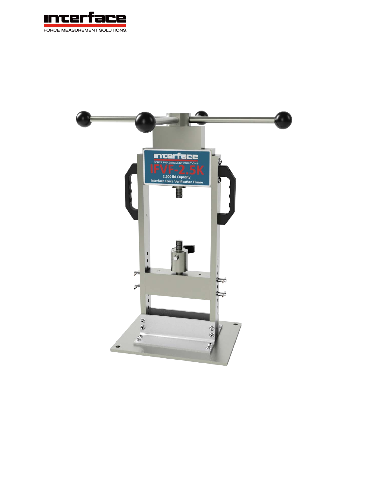
Interface Force Verification Frame IFVF
IFVF-2.5K

Interface Inc. ● 7418 East Helm Drive, Scottsdale, Arizona 85260 USA ● Phone 480.948.5555
www.interfaceforce.com Page 2of 10
Table of Contents
1. Introduction................................................................................................................3
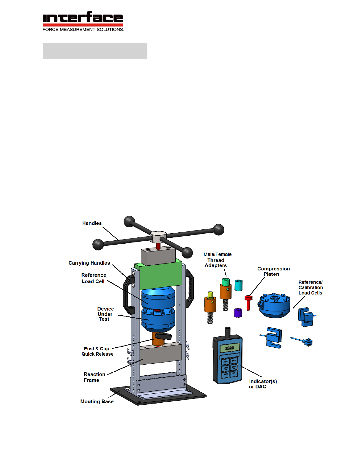
Equipment Description ........................................................................................3
System Components............................................................................................4
Theory of Operation.............................................................................................5
General Specifications.........................................................................................5
2. Warnings...................................................................................................................6
3. System Operation......................................................................................................7
Setup...................................................................................................................7
Operation.............................................................................................................7
Maintenance........................................................................................................8
4. Technical Support......................................................................................................9
Manual Revision: 2-A
Interface Inc. ● 7418 East Helm Drive, Scottsdale, Arizona 85260 USA ● Phone 480.948.5555
www.interfaceforce.com Page 3of 10
1. Introduction
Equipment Description
The Interface Force Verification Frame (IFVF) is a portable high force capacity
frame and accessories designed to apply tension and compression forces to load
cells with high resolution and accuracy. The system features a portable reaction
frame, manual actuator, thread/adapter accessories, and optional force sensor(s)
and instrumentation. The hardware can be used to verify operation of a device
under test or calibrate relative to a second reference load cell.
The base IFVF system includes the frame and tension/compression adapters.
Load cells, indicators, and additional adapter hardware are sold separately. The
items have been designed by Interface Inc. to work fully together for most common
applications.

Interface Inc. ● 7418 East Helm Drive, Scottsdale, Arizona 85260 USA ● Phone 480.948.5555
www.interfaceforce.com Page 4of 10
Interface Inc. Supplied Components
Component Description
IFVF-2.5K Components used to create and control both tension
and compression forces up to 2,500lbf. Features
reaction frame, manual turn force actuator, mounting
base, and carrying handles. Features 5/8-18 male
thread loading interface.
Compression Platen Component used to react compression forces.
Features smooth loading surface and 5/8-18 male
height adjustment threads.
Post/Cup Adapter Components used to impart tension forces. Features
male 5/8-18 male threads, post/cup mating features,
and quick release pin.
Optional Components (Sold Separately)
Component Description
Reference Load Cell Component used to measure the level of force being
created by the manual turn actuator as contained
within the reaction frame.
Force Readout Component used to display the level of force being
created within the reaction frame.
Device Under Test Component being force loaded within reaction frame.
Power Cables Components used to provide power to the load cell
and force indicator.
Adapter Hardware Components used to adapt between different thread
sizes and configurations. Interface Inc. can quote and
supply as needed.
Interface Inc. ● 7418 East Helm Drive, Scottsdale, Arizona 85260 USA ● Phone 480.948.5555
www.interfaceforce.com Page 5of 10
Theory of Operation
Turning the handles clockwise imparts a linear compression movement of
~0.007” per turn. Turning the verification frame handles counter-clockwise
imparts a linear tension movement of ~0.007” per turn. The exact level of
deflection changes based the stiffness of the load cell and/or device under test.
The force created is contained and reacted through the structural frame. The
Reference Load Cell measures the force being applied to the Device Under Test.
The verification frame can be used to verify operation of a Device Under Test or
calibrate relative to a second reference load cell.
General Specifications
Parameter Specification
Force Rating +/-2,500lbf Tension and Compression
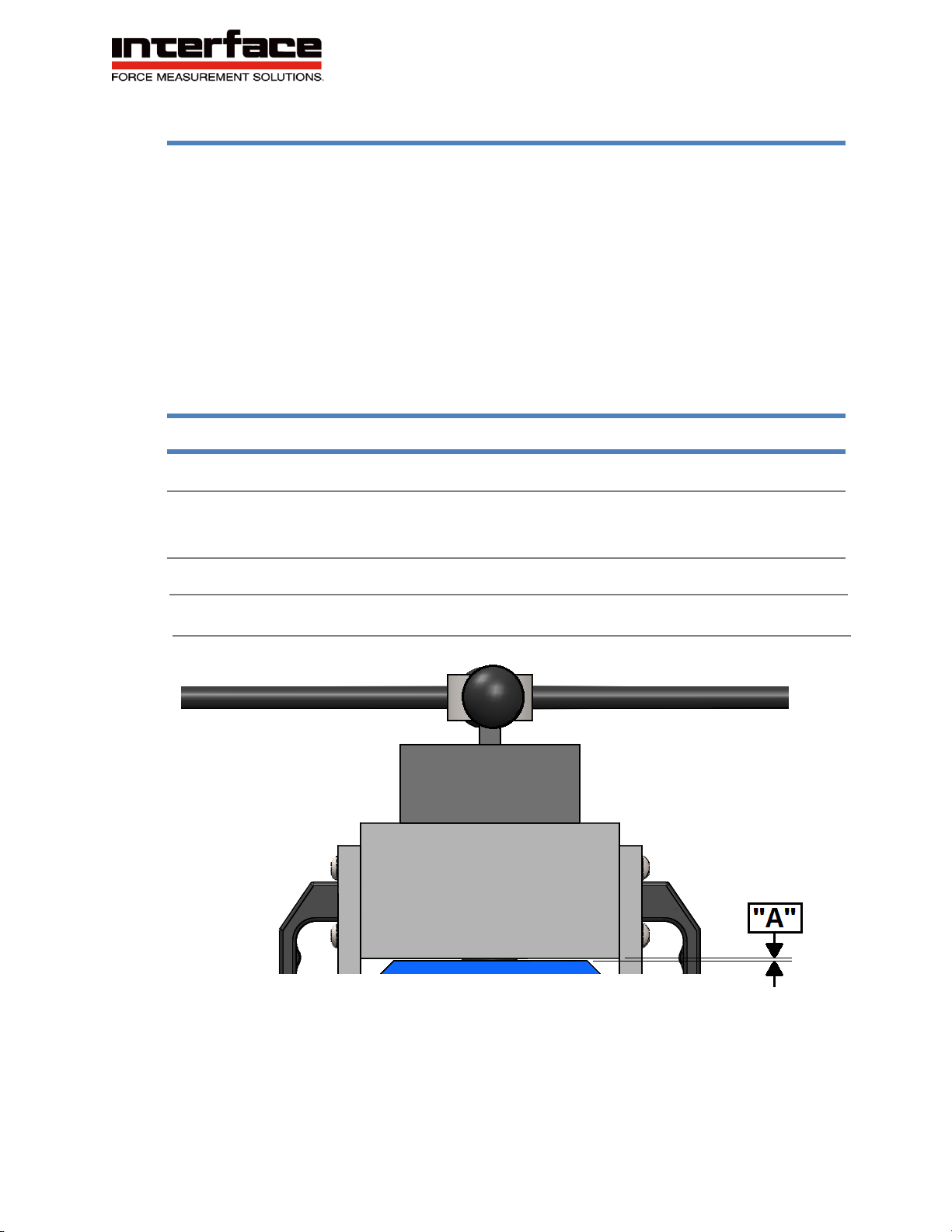
Force Actuation ~0.007” per turn, ~6 full turns, 16in Ball Knob Handles.
Reference Figure 1, below.
Size 8.0”x 10.0”x 20.0”, Under 20lbs.
Mounting Base 8.0” x 10.0”, 2x .41”Thru Holes for Mounting Bolts
Figure 1: Force Actuator Movement

Interface Inc. ● 7418 East Helm Drive, Scottsdale, Arizona 85260 USA ● Phone 480.948.5555
www.interfaceforce.com Page 6of 10
2. Warnings
General
It is very important that you study the following safety information as
to not result in a hazardous situation or equipment damage.
1. DO NOT SHOCK LOAD HANDLES WHILE TURNING/ACTUATING. Use only
smooth and gentle pressures with gradual accelerations and decelerations.
2. HARD STOPS are located at full extension and retraction of the actuator. Do
not apply high force or attempt to actuate past these hard stops. Damage to
the internal members of the verification frame will occur from overpressure at
hard stops.
3. Do not allow personnel to operate the verification frame who are not
experienced or trained in its use.
4. Keep fingers and hands free of potential pinch points of the verification frame.
Be aware of operating conditions at all times.
5. Do not exceed the verification frame force capacity of 2,500lbf by more than
10%.
6. Replace, remove and install hardware adapters only when verification frame is
unloaded of all levels of force.
Interface Inc. ● 7418 East Helm Drive, Scottsdale, Arizona 85260 USA ● Phone 480.948.5555
www.interfaceforce.com Page 7of 10
3. System Operation
Setup
1. Clamp or bolt the verification frame base to a sturdy surface. Ensure that
turning handles can freely rotate and are not obstructed.
2. Install desired hardware adapters needed for use.
a. Compression: Compression Platen
b. Tension: Tension Post/Cup
3. Position the bottom horizontal reaction frame member as
needed by removing and re-installing T-pins on the two vertical
side rails. Do NOT remove T-pins while any force is being
generated within the reaction frame.
4. Install load cell(s) within reaction frame per manufacturer guidelines.
5. Connect load cell wiring to indicators to display force values per manufacturer
guidelines.
Operation
1. Compression
a. Turn actuator counterclockwise gently until hard stop is reached, then turn
actuator 1 turn clockwise. Reference Figure 1.
b. Manually rotate compression platen until contact is made between loading
surfaces. Observe force increase/changes on electronic display.
(Between 0 and 30lbs actuation may be somewhat
non-linear as threaded connections engage unevenly.)
c. Rotate handles clockwise to increase compression magnitude.
d. Rotate handles counter-clockwise to decrease compression magnitude.
2. Tension
a. Turn actuator clockwise gently until hard stop is reached, then turn actuator
1 turn counterclockwise. Reference Figure 1.
b. Thread the Post of the Post/Cup Adapter into the load cell or Device Under
Test. Next, vertically position the Cup of the Post/Cup Adapter to best align
it to the Post. Using the Force Actuator turn handles, fine position the

Interface Inc. ● 7418 East Helm Drive, Scottsdale, Arizona 85260 USA ● Phone 480.948.5555
www.interfaceforce.com Page 8of 10
concentricity of the Post and Cup and then cross pin the two features
together.
c. Rotate handles counter-clockwise to increase tension magnitude.
d. Rotate handles clockwise to decrease tension magnitude.
Maintenance
The system is designed to operate with minimal maintenance requirements.
However, periodic maintenance should be performed to ensure trouble free
operation.
1. Daily
•Ensure handles turn smoothly throughout its range and do not bind
during movements.
2. Weekly
•Wipe down any surfaces that appear dirty.
•Apply light machine oil to cup/post hardware and thread adapters.
3. Monthly
•Inspect all moving joints for signs of wear/damage.
•Verify all fastener hardware is torqued and not loose.

Interface Inc. ● 7418 East Helm Drive, Scottsdale, Arizona 85260 USA ● Phone 480.948.5555
www.interfaceforce.com Page 9of 10
4. Technical Support
If you cannot find answers to your technical questions from the above sections,
you can use the Internet, e-mail, or telephone to contact Interface Inc. for
assistance.
www.interfaceforce.com: The website provides engineering contact information.
E-Mail: [email protected]
Telephone: 480-948-5555
Before you contact Interface Inc.
Interface Inc. can help you more efficiently if you have the following information
available when you contact us for support.
•Description of problem
•How long and how often has the problem occurred
•Troubleshooting attempts taken thus far
Be prepared to Troubleshoot
•Call from a telephone close to the verification frame so that you can
implement suggestions made over the phone.
•Write down any specific instructions and relevant information provided
during the support.
After you Contact Us
•Interface Inc. logs and tracks all technical support inquires to ensure that
you receive assistance for your problem or request. If you have questions
about the status of your problem or have additional information to report,
please contact Interface Inc. again.

Interface Inc. ● 7418 East Helm Drive, Scottsdale, Arizona 85260 USA ● Phone 480.948.5555
www.interfaceforce.com Page 10 of 10
Warranty
All force verification frame products from Interface Inc., ('Interface') are warranted
against defective material and workmanship for a period of (1) one year from the date of
dispatch. If the 'Interface' product you purchase appears to have a defect in material or
workmanship or fails during normal use within the period, please contact Interface
customer service, who will assist you in resolving the problem. If it is necessary to
return the product to 'Interface' please include a note stating name, company, address,
phone number and a detailed description of the problem. Also, please indicate if it is a
warranty repair. The sender is responsible for shipping charges, freight insurance and
proper packaging to prevent breakage in transit. 'Interface' warranty does not apply to
defects resulting from action of the buyer such as mishandling, improper interfacing,
operation outside of design limits, improper repair or unauthorized modification. No
other warranties are expressed or implied. 'Interface' specifically disclaims any implied
warranties of merchantability or fitness for a specific purpose. The remedies outlined
above are the buyer’s only remedies. 'Interface' will not be liable for direct, indirect,
special, incidental or consequential damages whether based on the contract, tort or
other legal theory.
Any corrective maintenance required after the warranty period should be performed by
'Interface' approved personnel only.
Table of contents
Other Interface Recording Equipment manuals


