manuals.online logo
Brands
  1. Home
  2. •
  3. Brands
  4. •
  5. Interlogix
  6. •
  7. Accessories
  8. •
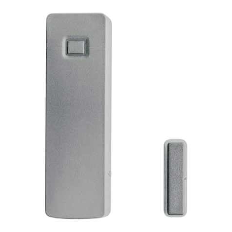
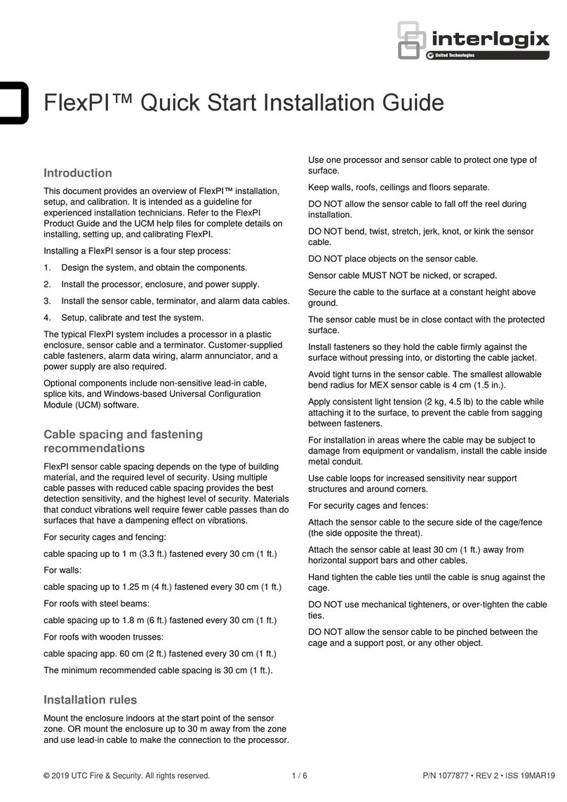
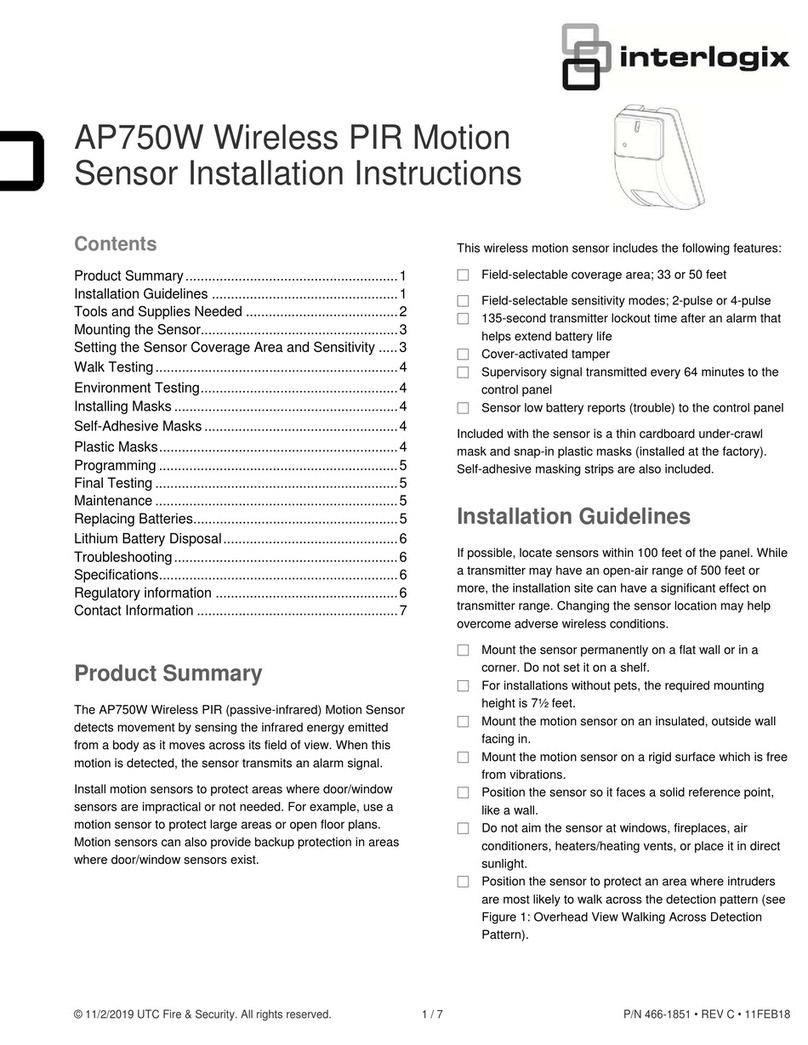
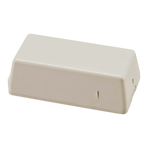
  9. Interlogix RF-1110-07-1 Assembly instructions

Interlogix RF-1110-07-1 Assembly instructions

© 2019 UTC Fire & Security Americas Corporation, Inc. 1 / 3 P/N 466-5445 • REV B • ISS 11JUN19
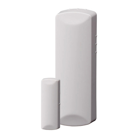
Wireless Micro DWS LoNa EN/Incert Installation
Sheet
EN
1
2
3
2 / 3 P/N 466-5445 • REV B • ISS 11JUN19
4
EN: Installation Sheet
Enrolling
To enroll the sensor, set your panel into program mode. Then
go to the Learn Sensors menu. Refer to your specific alarm
panel manual for details on these menus. Insert the battery.
Close the case (you will hear a click when the case latches are
engaging and disengaging). Then select the appropriate
sensor group and number.
Mounting
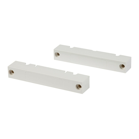
One side of the sensor is marked with an arrow poiting up; this
indicates the location of the reed switch. The magnet should be
mounted facing this side of the sensor. Please check the table
about distances to define the maximum distance in each
direction. See Figure 1.
Included with this device is double sided tape for the contact
and the magnet. Choose a suitable location for the sensor by
following the procedure in the section “Testing the Sensor”
ensuring desired signal strength is achieved. For reliable
bonding, ensure the surface is clean and dry. Apply the tape to
the sensor and then to the desired location. Apply firm
pressure for several seconds.
Note: When mounting with double sided tape, ensure
temperatures are above 10°C and will remain above 10°C for
at least 24 hours to ensure proper bond. After 24 hours, the
bond will hold at lower temperatures.
For security approved installations the contact back plate shall
be screwed to the mounting surface. Any removal from the
surface will activate the tamper.
An additional small screw is supplied in case you want to lock
the sensor cover to its base. Please check country specific
security standards whether this might be required. See
Figure 4.
Where possible, install sensors within 30 m of the panel. While
a transmitter may have an open-air range of 150 m or more,
the environment at the installation site may have a significant
effect on operational range. Changing a sensor location may
improve wireless communication.
Testing the Sensor (Test Weekly)
The sensor test verifies proper communication between the
sensor and the panel/receiver. To test the sensor, refer to the
specific panel/receiver documentation and do the following:
1. Put the panel/receiver into sensor test mode.
2. Open the door/window the sensor is protecting. The
sensor transmits a signal.
3. Listen for siren beeps to determine the appropriate
response.
4. Exit sensor test mode.
Installing/Replacing the Battery
WARNING: Lithium battery inside!
Risk of burned skin, blindness, or death.
Risk of explosion or disabled safeguard if the
battery is replaced by an incorrect type,
subjected to extremely low air pressure, or used
with another equipment.
Disposal into fire or a hot oven, heating above 100˚C,
mechanically crushing or cutting, disassembling, recharging,
short circuiting, or exposing the battery to water can result in
an explosion.
When the battery is low a signal will be sent to the control
panel. To install/replace the battery:
1. Slide the top cover to disengage it from the sensor, then
remove to reveal the battery.
2. Install/replace with a CR2032 battery ensuring the + side
of the battery faces towards you.
3. Re-attach the cover. Ensure the Top (as marked on the
inside of the cover) points away from the battery. You
should hear a click when the cover engages properly.
Note: Removing the cover will trigger a zone tamper signal to
the control panel.
Models
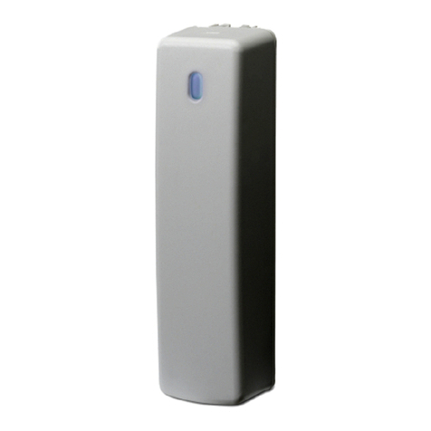
•RF-1110-07-1 -mini DWS LoNa, white
•RF-1110-07-3 -mini DWS LoNa, mahogany
P/N 466-5445 • REV B • ISS 11JUN19 3 / 3
Specifications
Compatibility
Interlogix LoNa transceivers (e.g. ZeroWire)
Wireless operating
frequency
433.65 MHz
Power output
-2 dBm EIRP
Quiescent current
1.4 µA
Maximum current
15 mA
Low voltage fault
2.2 V
Battery
3 V lithium CR2032
Battery Life
5-8 years
Magnet Gap
15.5 mm maximum
Operating environment
Temperature
Relative humidity
0 to 49°C
5 to 95% noncondensing
Distances
Distances are bidirectional unless specified in the table below.
Mounted on non-ferromagnetic material:
Approach distance X (switch closed)
15 mm
Removal distance X (switch open)
17mm
Approach distance (switch closed) Z+/Z-
35 / 32 mm
Removal distance (switch open) Z+/Z-
38 / 36 mm
Approach distance Y (switch closed)
23 mm
Removal distance Y (switch open)
27 mm
Minimum recommended installation distances are:
Approach distance X
10 mm
Approach distance Z
12 mm
Approach distance Y
16 mm
Regulatory information
Manufacturer
Placed on the market by:
UTC Fire & Security Americas Corporation, Inc.
3211 Progress Drive, Lincolnton, NC, 28092,
USA
Authorized EU manufacturing representative:
UTC Fire & Security B.V.
Kelvinstraat 7, 6003 DH Weert, Netherlands
Certification
INCERT C-001-1419
EN 50131-2-6:2008
Security Grade 2
Environmental class II
Tested and certified at Telefication B.V.
EU compliance
Warnings and
Disclaimers
THESE PRODUCTS ARE INTENDED FOR
SALE TO AND INSTALLATION BY QUALIFIED
PROFESSIONALS. UTC FIRE & SECURITY
CANNOT PROVIDE ANY ASSURANCE THAT
ANY PERSON OR ENTITY BUYING ITS
PRODUCTS, INCLUDING ANY “AUTHORIZED
DEALER” OR “AUTHORIZED RESELLER”, IS
PROPERLY TRAINED OR EXPERIENCED TO
CORRECTLY INSTALL FIRE AND SECURITY
RELATED PRODUCTS.
For more information on warranty disclaimers and
product safety information, please check
https://firesecurityproducts.com/policy/product-
warning/ or scan the QR code.
European Union
directives
UTC Fire & Security hereby declares that this
device is in compliance with the applicable
requirements and provisions of all applicable
rules and regulations, including but not limited to
the Directive 2014/53/EU. For more information
see: https://www.utcfssecurityproducts.eu/
2012/19/EU (WEEE directive): Products marked
with this symbol cannot be disposed of as
unsorted municipal waste in the European Union.
For proper recycling, return this product to your
local supplier upon the purchase of equivalent
new equipment, or dispose of it at designated
collection points. For more information see:
www.utcfssecurityproducts.eu/recycle/.
2006/66/EC (battery directive): This product
contains a battery that cannot be disposed of as
unsorted municipal waste in the European Union.
See the product documentation for specific
battery information. The battery is marked with
this symbol, which may include lettering to
indicate cadmium (Cd), lead (Pb), or mercury
(Hg). For proper recycling, return the battery to
your supplier or to a designated collection point.
For more information see:
www.utcfssecurityproducts.eu/recycle/.
Contact information
www.utcfireandsecurity.com or www.interlogix.com
Customer support
For customer support, see www.utcfssecurityproducts.eu

This manual suits for next models

1

Other Interlogix Accessories manuals

Interlogix VE700AM Series Assembly instructions

Interlogix

Interlogix VE700AM Series Assembly instructions

Interlogix ADC-IS-300-LP User manual

Interlogix

Interlogix ADC-IS-300-LP User manual

Interlogix RF-DC101 Series Assembly instructions

Interlogix

Interlogix RF-DC101 Series Assembly instructions

Interlogix SDX-135Z-433 User manual

Interlogix

Interlogix SDX-135Z-433 User manual

Interlogix 319.5 User manual

Interlogix

Interlogix 319.5 User manual

Interlogix HDX-135Z-433 User manual

Interlogix

Interlogix HDX-135Z-433 User manual

Interlogix ShatterPro II User manual

Interlogix

Interlogix ShatterPro II User manual

Interlogix Wireless ShatterPro 5845 User manual

Interlogix

Interlogix Wireless ShatterPro 5845 User manual

Interlogix AP750W User manual

Interlogix

Interlogix AP750W User manual

Interlogix RF-1012-07-5 Assembly instructions

Interlogix

Interlogix RF-1012-07-5 Assembly instructions

Interlogix RCR-REX User manual

Interlogix

Interlogix RCR-REX User manual

Interlogix TX-E611 Assembly instructions

Interlogix

Interlogix TX-E611 Assembly instructions

Interlogix International ShatterPro Assembly instructions

Interlogix

Interlogix International ShatterPro Assembly instructions

Interlogix SDX-135Z User manual

Interlogix

Interlogix SDX-135Z User manual

Interlogix TX-6010-03-1 Assembly instructions

Interlogix

Interlogix TX-6010-03-1 Assembly instructions

Interlogix SENTROL 1045T Series User manual

Interlogix

Interlogix SENTROL 1045T Series User manual

Interlogix HDX-135 User manual

Interlogix

Interlogix HDX-135 User manual

Interlogix TX-C series User manual

Interlogix

Interlogix TX-C series User manual

Interlogix ShatterPro Assembly instructions

Interlogix

Interlogix ShatterPro Assembly instructions

Interlogix VE700 series Assembly instructions

Interlogix

Interlogix VE700 series Assembly instructions

Interlogix Learn Mode Freeze Sensor User manual

Interlogix

Interlogix Learn Mode Freeze Sensor User manual

Interlogix 60-886-95 User manual

Interlogix

Interlogix 60-886-95 User manual

Interlogix DC115 Assembly instructions

Interlogix

Interlogix DC115 Assembly instructions

Interlogix ShatterPro 60-873-95 User manual

Interlogix

Interlogix ShatterPro 60-873-95 User manual

Popular Accessories manuals by other brands

Sontay GS-S-CO-W quick start guide

Sontay

Sontay GS-S-CO-W quick start guide

Generac Power Systems 6297 Installation and operating instructions

Generac Power Systems

Generac Power Systems 6297 Installation and operating instructions

Lincoln Mityvac MV4535 user manual

Lincoln

Lincoln Mityvac MV4535 user manual

IVT PKS 1000 Installer's guide

IVT

IVT PKS 1000 Installer's guide

Sewha SI 480E instruction manual

Sewha

Sewha SI 480E instruction manual

ATN NVG-7 user guide

ATN

ATN NVG-7 user guide

Matelec COBRA IP65 manual

Matelec

Matelec COBRA IP65 manual

Greengate ONW-P-1001-MV-W installation instructions

Greengate

Greengate ONW-P-1001-MV-W installation instructions

Orno OR-CR-257 Operating and installation instructions

Orno

Orno OR-CR-257 Operating and installation instructions

NuAire NU-8625 Operation and maintenance manual

NuAire

NuAire NU-8625 Operation and maintenance manual

Fresh 'N Rebel 2PB6000 manual

Fresh 'N Rebel

Fresh 'N Rebel 2PB6000 manual

Banner Q5X quick start guide

Banner

Banner Q5X quick start guide

Omron E32 - datasheet

Omron

Omron E32 - datasheet

ORION TELESCOPES & BINOCULARS StarShoot Video Eyepiece II instruction manual

ORION TELESCOPES & BINOCULARS

ORION TELESCOPES & BINOCULARS StarShoot Video Eyepiece II instruction manual

Polaroid PLAY PL-2000-00 quick start guide

Polaroid

Polaroid PLAY PL-2000-00 quick start guide

S+S Regeltechnik Thermasgard ETF 5 Series Operating Instructions, Mounting & Installation

S+S Regeltechnik

S+S Regeltechnik Thermasgard ETF 5 Series Operating Instructions, Mounting & Installation

Manitowoc K00055 installation instructions

Manitowoc

Manitowoc K00055 installation instructions

Wellcare WE-167UBAHD instruction manual

Wellcare

Wellcare WE-167UBAHD instruction manual

manuals.online logo
manuals.online logoBrands
  • About & Mission
  • Contact us
  • Privacy Policy
  • Terms and Conditions

Copyright 2025 Manuals.Online. All Rights Reserved.