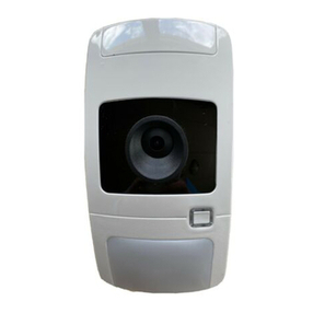
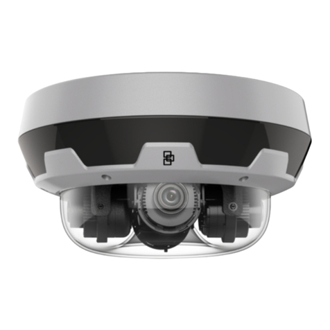
Interlogix UVD-XP4DNR User manual

UVD-XP4DNR(-P)
Camera Quick Start
Guide
EN UVD-XP4DNR(-P) Quick Start Guide
DE UVD-XP4DNR(-P) -Kurzanleitung
ES Guía de inicio rápido de la cámara UVD-XP4DNR(-P)
FR Guide de démarrage rapide du dôme UVD-XP4DNR(-P)
IT Guida di avvio rapido dei modelli a standard aperti di
telecamera dome UVD-XP4DNR(-P)
NL UVD-XP4DNR(-P) Dome Beknopte handleiding
PL UVD-XP4DNR(-P) Dome — instrukcja szybkiego
uruchamiania
PT Guia rápido de dome UVD-XP4DNR(-P)
RU Краткое руководство: камера UVD-XP4DNR(-P)
TR UVD-XP4DNR(-P) Kamera HızlıBaşlangıç Kılavuzu
P/N 1079205B • REV 1.0 • ISS 22MAR12

Copyright © 2012 UTC Fire & Security. All rights reserved.
Trademarks and
patents
Interlogix, UltraView names and logos are trademarks of
UTC Fire & Security.
Other trade names used in this document may be trademarks
or registered trademarks of the manufacturers or vendors of the
respective products.
Manufacturer UTC Fire & Security Americas Corporation, Inc.
2955 Red Hill Avenue, Costa Mesa, CA 92626-5923, USA
Authorized EU manufacturing representative:
UTC Fire & Security B.V.
Kelvinstraat 7, 6003 DH Weert, The Netherlands
Certification
N4131
FCC compliance Class A: This equipment has been tested and found to comply
with the limits for a Class A digital device, pursuant to part 15 of
the FCC Rules. These limits are designed to provide
reasonable protection against harmful interference when the
equipment is operated in a commercial environment. This
equipment generates, uses, and can radiate radio frequency
energy and, if not installed and used in accordance with the
instruction manual, may cause harmful interference to radio
communications. Operation of this equipment in a residential
area is likely to cause harmful interference in which case the
user will be required to correct the interference at his own
expense.
ACMA compliance Notice! This is a Class A product. In a domestic environment
this product may cause radio interference in which case the
user may be required to take adequate measures.
Canada This Class A digital apparatus complies with Canadian ICES-
003.
Cet appareil numérique de la classe A est conforme à la norme
NMB-0330 du Canada.
European Union
directives
12004/108/EC (EMC directive): Hereby, UTC Fire & Security
declares that this device is in compliance with the essential
requirements and other relevant provisions of Directive
2004/108/EC.
2002/96/EC (WEEE directive): Products marked with this
symbol cannot be disposed of as unsorted municipal waste in
the European Union. For proper recycling, return this product to
your local supplier upon the purchase of equivalent new
equipment, or dispose of it at designated collection points. For
more information see: www.recyclethis.info.
Contact
information
For contact information, see www.interlogix.com or
www.utcfssecurityproducts.eu.

Quick Start Guide 3 EN
EN
Description
The UVD-XP4DNR(-P) camera consists of the following parts:
• The camera assembly
• Monitor output cable
• Mounting screws, wall anchors, and hex key
Figure 1: The camera assembly and monitor output cable
1. Lens body 5. Camera body
2. Bubble 6. Monitor output BNC
3. Video monitor output 7. Monitor output RCA
4. OSD control pad
Use the video output BNC and power jack for normal system
operation. Use the monitor output cable for installation and
maintenance.

EN 4 Quick Start Guide
OSD control pad
The onscreen display (OSD) control pad is a five-direction joystick that
provides the ability to manually control the camera functions.
OSD control pad
Table 1 lists the OSD control pad functions and describes their use.
Table 1: OSD control pad functions
Pad directions Description
Up Moves the cursor upward to select an item.
Left Moves the cursor left to select or adjust the parameters
of the selected item.
Right Moves the cursor to the right to select or adjust the
parameters of the selected item.
Down Moves the cursor downward to select an item.
Enter Press the center of the control pad to display the Setup
menu. If the selected item has its own menu, press the
control pad to enter a submenu. Press the control pad for
2 seconds to save all settings and exit the Setup menu.
Installation
Complete all the necessary programming before you install the
camera. This section provides information on how to install the camera
and adjust camera angle and focus.
WARNING: To reduce the risk of fire or electronic shock, do not
expose the camera to rain or moisture and do not remove the cover or
back.

Quick Start Guide 5 EN
Cable connection
To make cable connections, do the following:
1. Connect a coaxial cable from the camera’s BNC connector to a
CCTV monitor or video recording device.
2. Connect a 12 VDC or 24 VAC power supply to the power input.
The label on the camera gives the following information:
Red cable. Power in.
Black cable. Power in.
White cable. Video out.
Black cable. Video ground.
Note: For AC24V or DC12V, Black or Red may be used for ground.
Camera installation
To mount the camera, attach the camera to the mounting surface using
the appropriate fasteners.
Angle adjustment
To adjust the horizontal angle of the platform up to 180 degrees, turn
the platform (1).
To adjust the horizontal angle of the rotor up to 350 degrees, turn the
rotor on the platform (2).
To adjust the vertical angle of the platform up to 90 degrees, turn the
platform (3).

EN 6 Quick Start Guide
Focus adjustment
To adjust the camera zoom and focus:
1. Zoom ring thumbscrew for VA2 and focus ring for VA9 lens.
2. Focus ring thumbscrew for VA2 and zooming ring for VA9 lens.
1. Loosen the zoom ring thumbscrew.
2. Turn the zoom ring to set the desired zoom.
3. Tighten the zoom ring thumbscrew.
4. Loosen the focus ring thumbscrew.
5. Turn the focus ring to set the desired focus.
6. Tighten the focus ring thumbscrew.
Connect the monitor
Program the cameras by attaching a standard video monitor to the
system.
To connect the monitor, do the following:
1. Plug the monitor output cable to the video monitor output
connector.
2. Connect the BNC cable to the video monitor.
3. Press the OK button to display the Setup menu.
Programming
The camera is configured through the setup menus which appear on-
screen. See Figure 2.

Quick Start Guide 7 EN
Figure 2: Main menu
To access and navigate the menus, press and hold the center of the
OSD control pad. Press Up or Down on the control pad to move
between items, and press Enter (center of the control pad) to select the
item. Press Right or Left on the control pad to select the different
options available for the item.
You can return to the previous menu from any of the menus (except
the Main menu) by selecting the Previous page option.
The menu map is shown on the back page of this manual.
Refer to the User Manual for detailed programming instructions.
Table 2: Main menu options
Menu option Description
Preset Preset settings.
Setup Camera ID, Line Lock, motion detection, and WDR settings.
Viewing Flip and resolution settings
Exposure AGC, AE preferences, range control, shutter limit, frame
RPT, and B/W control settings.
White balance White balance settings.
Save/Restore Save and restore user and factory settings.
Specifications
Electrical
Power Input 12 VDC or 24 VAC
Power consumption 3W (DC); 2.4 W (AC)

EN 8 Quick Start Guide
Environmental and physical
Weight 33.8 oz. (958 g)
Dimensions 5.22 x 4.11 in. (133 x 105 mm)
Operating Temperature -58 to +122°F (-50 to +50°C)
Weather resistant IP66

Schnell Start Anleitung 9 DE
DE
Beschreibung
Die folgenden Teile sind im Lieferumfang der UVD-XP4DNR(-P)
Kamera enthalten:
• Kamera
• Monitorausgangskabel
• Montageschrauben, Dübel für Wandmontage und
Sechskantschlüssel
Abbildung 1: Kamera und Monitorausgangskabel
1. Objektiv 5. Kameragehäuse
2. Kuppel 6. Monitorausgang (BNC)
3. Videomonitorausgang 7. Monitorausgang (Cinch)
4. OSD-Steuerung
Verwenden Sie die Videoausgangsbuchse (BNC) und die
Stromversorgungsbuchse für den normalen Systembetrieb.
Verwenden Sie das Monitorausgangskabel für Installations- und
Wartungszwecke.

DE 10 Schnell Start Anleitung
OSD-Steuerung
Die OSD-Steuerung (On-Screendisplay) erfolgt über einen in fünf
Richtungen verstellbaren Joystick, mit dem die Kamerafunktionen
manuell gesteuert werden können.
OSD-Steuerung
In Tabelle 1 befinden sich die OSD-Steuerungsfunktionen und eine
Beschreibung ihres Verwendungszwecks.
Tabelle 1: Funktionen der OSD-Steuerung
Steuerrichtungen Beschreibung
Nach oben Bewegt den Cursor nach oben, um ein Element
auszuwählen.
Nach links Bewegt den Cursor nach links, um Parameter für das
ausgewählte Element auszuwählen oder anzupassen.
Nach rechts Bewegt den Cursor nach rechts, um Parameter für das
ausgewählte Element auszuwählen oder anzupassen.
Nach unten Bewegt den Cursor nach unten, um ein Element
auszuwählen.
Enter Drücken Sie die Mitte der Steuerung, um das Setup-
Menü aufzurufen. Wenn das ausgewählte Element ein
eigenes Menü besitzt, drücken Sie die Steuerung, um in
ein Untermenü zu gelangen. Halten Sie die Steuerung 2
Sekunden gedrückt, um alle Einstellungen zu speichern
und das Setup-Menü zu beenden.
Installation
Führen Sie vor dem Installieren der Kamera alle erforderlichen
Programmierungsschritte aus. In diesem Abschnitt finden Sie
Informationen zur Installation der Kamera und zur Einstellung von
Kamerawinkel und -fokus.

Schnell Start Anleitung 11 DE
WARNUNG: Um das Risiko eines Brandes oder elektrischen Schlages
zu vermeiden, sollten Sie die Kamera vor Regen und Feuchtigkeit
schützen sowie die obere und hintere Abdeckung nicht entfernen.
Kabelanschluss
So schließen Sie die Kabel an:
1. Verbinden Sie ein Koaxialkabel vom BNC-Anschluss der Kamera
mit einem Überwachungsmonitor oder Videoaufzeichnungsgerät.
2. Schließen Sie eine 12-V-Gleichstromquelle oder 24-V-
Wechselstromquelle an den Stromeingang an. Auf dem Etikett der
Kamera finden Sie die folgenden Informationen:
Rotes Kabel. Stromversorgung.
Schwarzes Kabel. Stromversorgung.
Weißes Kabel. Videoausgang.
Schwarzes Kabel. Video-Masseanschluss.
Hinweis: Für AC24V oder DC12V kann das schwarze oder rote Kabel
als Masseanschluss verwendet werden.
Installation der Kamera
Zur Montage der Kamera befestigen Sie diese mit den dafür
vorgesehenen Befestigungselementen an der Montagefläche.
Winkeleinstellung
Den horizontalen Winkel der Plattform können Sie auf bis zu 180 Grad
einstellen, indem Sie die Plattform (1) drehen.

DE 12 Schnell Start Anleitung
Den horizontalen Winkel des Rotors können Sie auf bis zu 350 Grad
einstellen, indem Sie den Rotor auf der Plattform (2) drehen.
Den vertikalen Winkel der Plattform können Sie auf bis zu 90 Grad
einstellen, indem Sie die Plattform (3) drehen.
Einstellung des Fokus
So passen Sie Zoom und Fokus der Kamera an:
1. Zoom-Ringschraube für VA2-Objektiv und Fokus-Ringschraube für VA9-
Objektiv.
2. Fokus-Ringschraube für VA2-Objektiv und Zoom-Ringschraube für VA9-
Objektiv.
1. Lösen Sie die Schraube am Zoom-Ring.
2. Drehen Sie den Zoom-Ring, bis der gewünschte Zoom eingestellt
ist.
3. Ziehen Sie die Schraube am Zoom-Ring fest.
4. Lösen Sie die Schraube am Fokusring.
5. Drehen Sie den Fokusring, bis die gewünschte Bildschärfe
eingestellt ist.
6. Ziehen Sie die Schraube am Fokusring fest.
Anschließen des Monitors
Sie programmieren die Kameras, indem Sie einen Standard-
Videomonitor an das System anschließen.
So schließen Sie den Monitor an:
1. Schließen Sie das Monitorausgangskabel an den
Videomonitorausgang an.
2. Schließen Sie das BNC-Kabel an den Videomonitor an.
3. Drücken Sie die Taste OK, um das Setup-Menü anzuzeigen.

Schnell Start Anleitung 13 DE
Programmierung
Die Kamera wird über die Setup-Menüs konfiguriert, die am Bildschirm
angezeigt werden. Siehe Figure 2.
Abbildung 2: Hauptmenü
Um zu den Menüs zu gelangen und darin zu navigieren, müssen Sie
die Mitte der OSD-Steuerung gedrückt halten. Drücken Sie die
Steuerung nach oben oder unten, um zwischen den Menüpunkten zu
wechseln, und drücken Sie "Enter" (Mitte der Steuerung), um einen
Menüpunkt auszuwählen. Drücken Sie die Steuerung nach links oder
rechts, um die verschiedenen Optionen für den jeweiligen Menüpunkt
auszuwählen.
Sie können von jedem Menü aus zum vorherigen Menü zurückkehren,
indem Sie die Option Previous Page (Vorherige Seite) auswählen (mit
Ausnahme des Hauptmenüs).
Auf der letzten Seite des Handbuchs befindet sich eine Menüstruktur.
Detaillierte Programmieranweisungen finden Sie im
Benutzerhandbuch.
Tabelle 2: Optionen des Hauptmenüs
Menüoption Beschreibung
Preset Preset-Einstellungen.
Setup Kamera-ID, LineLock, Bewegungserkennung und WDR-
Einstellungen.
Viewing (Anzeige) Einstellungen für die Kippfunktion und die Auflösung.

DE 14 Schnell Start Anleitung
Menüoption Beschreibung
Exposure
(Bildverstärkung)
AGC (Automatische Verstärkungsregelung), AE-
Einstellungen, Bereichssteuerung,
Verschlussgeschwindigkeit, Frame RPT und S/W-
Steuerung.
White balance
(Weißabgleich)
Einstellungen zum Weißabgleich.
Save/Restore
(Speichern/
Wiederherstellen)
Benutzer- und Werkseinstellungen speichern und
wiederherstellen.
Technische Daten
Elektrik
Spannungsversorgung 12V DC oder 24V AC
Leistungsaufnahme 3W (DC); 2,4W (AC)
Umgebung und Spezifikationen
Gewicht 958g
A
bmessungen 133 x 105mm
Betriebstemperatur -58 bis +122°F (-50 bis +50°C)
Witterungsbeständig IP66

Guía de inicio rápido 15 ES
ES
Descripción
La cámara UVD-XP4DNR(-P) consta de las siguientes partes:
• El conjunto de la cámara
• Cable de salida del monitor
• Tornillos de montaje, sujeciones de pared y llave hexagonal
Figura 1: el conjunto de la cámara y el cable de salida del monitor
1. Cuerpo de la lente 5. Cuerpo de la cámara
2. Burbuja 6. Conector BNC de salida del
monitor
3. Salida de vídeo del monitor 7. Conector RCA de salida del
monitor
4. Botón direccional de
control OSD
El conector BNC de salida de vídeo y la clavija de alimentación se
utilizan para el funcionamiento normal del sistema. El cable de salida
del monitor se utiliza para la instalación y el mantenimiento.

ES 16 Guía de inicio rápido
Botón direccional de control OSD
El botón direccional de control de visualización en pantalla (OSD)
consiste en un mando de cinco direcciones con el que se pueden
controlar manualmente las funciones de la cámara.
Botón direccional de
control OSD
La tabla 1 muestra las funciones de este botón direccional de control
OSD y explica cómo utilizarlas.
Tabla 1: funciones del botón direccional de control OSD
Dirección del
botón
Descripción
Up El cursor se mueve hacia arriba para seleccionar un
elemento.
Left El cursor se mueve hacia la izquierda para seleccionar
o ajustar los parámetros del elemento seleccionado.
Right El cursor se mueve hacia la derecha para seleccionar
o ajustar los parámetros del elemento seleccionado.
Down El cursor se mueve hacia abajo para seleccionar un
elemento.
Enter Pulse el centro del botón direccional y aparecerá en
pantalla el menú Setup (Configuración). Si el elemento
seleccionado dispone de un menú propio, pulse el botón
direccional para acceder al submenú. Pulse el botón
direccional durante 2 segundos para guardar la
configuración y salir del menú Setup (Configuración).
Instalación
Realice todos los ajustes de programación necesarios antes de
instalar la cámara. Esta sección proporciona información acerca de
la instalación de la cámara, además de instrucciones para ajustar el
ángulo y el enfoque de la misma.

Guía de inicio rápido 17 ES
ADVERTENCIA: para reducir el riesgo de incendio o de descargas
eléctricas, no exponga la cámara a la lluvia o la humedad ni retire la
cubierta o la tapa posterior.
Conexión del cable
Para realizar las conexiones de los cables, haga lo siguiente:
1. Conecte un cable coaxial del conector BNC de la cámara a un
monitor CCTV o a un dispositivo de grabación de vídeo.
2. Conecte una fuente de alimentación de 12 VCC o 24 VCA
a la entrada de alimentación. En la etiqueta de la cámara
se proporciona la siguiente información:
Cable rojo. Entrada de alimentación.
Cable negro. Entrada de alimentación.
Cable blanco. Salida de vídeo.
Cable negro. Toma de tierra de vídeo.
Nota: para CA 24V o CC 12V, se pueden usar Black (cable negro)
o Red (cable rojo) como toma de tierra.
Instalación de la cámara
Para montar la cámara, fíjela en la superficie de montaje con las
sujeciones adecuadas.
Ajuste del ángulo
Para ajustar el ángulo horizontal de la plataforma hasta los
180 grados, gire la plataforma (1).

ES 18 Guía de inicio rápido
Para ajustar el ángulo horizontal del rotor hasta los 350 grados, haga
girar el rotor sobre la plataforma (2).
Para ajustar el ángulo vertical de la plataforma hasta los 90 grados,
gire la plataforma (3).
Ajuste del foco
Para ajustar el zoom y el enfoque de la cámara:
1. Tornillo de palometa del anillo del zoom para lente VA2 y anillo de enfoque
para lente VA9.
2. Tornillo de palometa del anillo de enfoque para lente VA2 y anillo de zoom
para lente VA9.
1. Afloje el tornillo de palometa del anillo del zoom.
2. Gire el anillo del zoom hasta conseguir el zoom deseado.
3. Apriete el tornillo de palometa del anillo del zoom.
4. Afloje el tornillo de palometa del anillo del enfoque.
5. Gire el anillo del enfoque hasta conseguir el enfoque deseado.
6. Apriete el tornillo de palometa del anillo del enfoque.
Conexión del monitor
Programe las cámaras conectando un monitor de vídeo estándar al
sistema.
Para conectar el monitor, haga lo siguiente:
1. Conecte el cable de salida del monitor al conector de salida de
vídeo del monitor.
2. Conecte el cable del conector BNC al monitor de vídeo.
3. Pulse el botón OK para mostrar el menú Setup (Configuración).

Guía de inicio rápido 19 ES
Programación
La cámara se configura mediante los menús de configuración que
aparecen en la pantalla. Consulte la Figure 2.
Figura 2: Menú Main (Principal)
Para acceder a los menús y desplazarse por ellos, pulse y mantenga
pulsado el centro del botón direccional de control OSD. Mueva el
botón direccional arriba o abajo para desplazarse por los elementos y
púlselo para seleccionar uno. Mueva el botón direccional a la derecha
o izquierda para seleccionar las distintas opciones que hay disponibles
para el elemento seleccionado.
Puede volver al menú anterior desde cualquier menú (excepto desde
el menú Main (Principal)) seleccionando la opción Previous page
(Página anterior).
El mapa de menús está disponible en la ultima página de este manual.
Consulte el manual de usuario para obtener más instrucciones sobre
programación.
Tabla 2: Opciones del menú principal
Opción del menú Descripción
Preset (Posición
preestablecida)
Configuración de preset.
Configuración o
programación (Prog)
ID de la cámara, sincronismo por línea, detección
de movimiento y configuración de WDR.
Viewing (Visualización) Configuraciones de Flip (Giro) y resolución.
Exposure (Exposición) CAG, Preferencias AE, control de alcance, límite del
obturador, repetición de fotogramas, y
configuraciones del control de B/N.

ES 20 Guía de inicio rápido
Opción del menú Descripción
White balance (Balance
de blancos)
Configuraciones del balance de blancos.
Save/Restore (Guardar/
Restaurar)
Guardar y restaurar configuraciones del usuario y
de fábrica.
Especificaciones
Eléctrica
Entrada de alimentación 12 VCC o 24 VCA
Consumo de energía 3W (CC); 2,4 W (CA)
Físicas y ambientales
Peso 958 g
Dimensiones 133 x 105 mm. (5,22 x 4,11 pulg.)
Temperatura de funcionamiento -58 a +122°F (-50 a +50°C)
Resistente al clima IP66
Other manuals for UVD-XP4DNR
1
This manual suits for next models
1
Table of contents
Languages:
Other Interlogix Digital Camera manuals

Interlogix
Interlogix TVB-6101 User manual

Interlogix
Interlogix TruVision TVC-6110-1-N User manual

Interlogix
Interlogix TruVision Multi-Imager User manual

Interlogix
Interlogix TVC-2401 User manual

Interlogix
Interlogix TruVision 12MP User manual

Interlogix
Interlogix TVC-2401 User manual

Interlogix
Interlogix UltraView UVC-6130-1 User manual

Interlogix
Interlogix UltraView UVC-6120-1 User manual

Interlogix
Interlogix TruVision 360 Instruction sheet

Interlogix
Interlogix Camera User manual