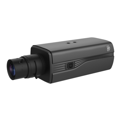
Interlogix TruVision 12MP User manual

TruVision 6MP and
12MP 360° Camera
Installation Manual
P/N 1073656-EN • REV C • ISS 14OCT19

Copyright © 2019 United Technologies Corporation,
Interlogix is part of UTC Climate, Controls & Security, a unit of United
Technologies Corporation. All rights reserved.
Trademarks and
patents
Trade names used in this document may be trademarks or registered trademarks
of the manufacturers or vendors of the respective products.
Disclaimer Information in this document is subject to change without notice. No part of this
document may be reproduced or transmitted in any form or by any means,
electronic or mechanical, for any purpose, without the express written permission
of UTC Fire & Security Americas Corporation, Inc.
Manufacturer
Interlogix.
2955 Red Hill Avenue, Costa Mesa, CA 92626-5923, USA
Authorized EU manufacturing representative:
UTC Fire & Security B.V.
Kelvinstraat 7, 6003 DH Weert, The Netherlands
Certification
FCC compliance Class A: This equipment has been tested and found to comply with the limits for
a Class A digital device, pursuant to part 15 of the FCC Rules. These limits are
designed to provide reasonable protection against harmful interference when the
equipment is operated in a commercial environment. This equipment generates,
uses, and can radiate radio frequency energy and, if not installed and used in
accordance with the instruction manual, may cause harmful interference to radio
communications. Operation of this equipment in a residential area is likely to
cause harmful interference in which case the user will be required to correct the
interference at his own expense.
FCC conditions This device complies with Part 15 of the FCC Rules. Operation is subject to the
following two conditions:
(1) This device may not cause harmful interference.
(2) This Device
must accept any interference received, including interference that
may cause undesired operation.
ACMA compliance Notice! This is a Class A product. In a domestic environment this product may
cause radio interference in which case the user may be required to take
adequate measures.
Canada This Class A digital apparatus complies with Canadian ICES-003.
Cet appareil numérique de la classe A est conforme à la norme NMB-0330 du
Canada.
cUL Safety Instruction:
Improper use or replacement of the battery may result in explosion hazard.
Replace with the same or equivalent type only. Dispose of used batteries in
conformance with the local codes.
Instructions de sécurité :
L’utilisation ou le remplacement inadéquats de la pile peuvent entraîner un risque
d’explosion. Remplacez-la par le même type ou l’équivalent du même type
seulement. Jetez les piles usagées conformément aux directives fournies par le
fabricant de la pile.
European Union
directives
This product and - if applicable - the supplied accessories too are marked with
"CE" and comply therefore with the applicable harmonized European standards
listed under the EMC Directive 2014/30/EU, the RoHS Directive 2011/65/EU.
2012/19/EU (WEEE directive): Products marked with this symbol cannot be
disposed of as unsorted municipal waste in the European Union. For proper
recycling, return this product to your local supplier upon the purchase of
equivalent new equipment, or dispose of it at designated collection points. For
more information see: www.recyclethis.info.
2013/56/EU & 2006/66/EC (battery directive): This product contains a battery
that cannot be disposed of as unsorted municipal waste in the European Union.
See the product documentation for specific battery information. The battery is
marked with this symbol, which may include lettering to indicate cadmium (Cd),
lead (Pb), or mercury (Hg). For proper recycling, return the battery to your
supplier or to a designated collection point. For more information see:
www.recyclethis.info.
Product warnings
and disclaimers
THESE PRODUCTS ARE INTENDED FOR SALE TO AND INSTALLATION BY
QUALIFIED PROFESSIONALS. UTC FIRE & SECURITY CANNOT PROVIDE
ANY ASSURANCE THAT ANY PERSON OR ENTITY BUYING ITS PRODUCTS,
INCLUDING ANY “AUTHORIZED DEALER” OR “AUTHORIZED RESELLER”, IS
PROPERLY TRAINED OR EXPERIENCED TO CORRECTLY INSTALL FIRE
AND SECURITY RELATED PRODUCTS.
For more information on warranty disclaimers and product safety information,
please check www.firesecurityproducts.com/policy/product-warning/ or scan the
following code:
Contact information
and manuals/ tools/
firmware
For contact information and to download the latest manuals, tools, and firmware,
go to the web site of your region:
Americas: www.interlogix.com
EMEA: www.firesecurityproducts.com
Manuals are available in several languages.
Australia/New Zealand: www.utcfs.com.au


Installation Manual 1
Content
Introduction 2
Product overview 2
Installation 2
Installation environment 2
Contact information and manuals/tools/firmware 3
Package contents 3
Cable requirements 5
Camera description 5
Install the camera 6
IR illuminators 9
Accessing the SD card 9
Mounting accessories 10
Using the camera with an Interlogix NVR or another system 11
Using the camera with TruVision Navigator 11
Specifications 13
Pin definitions 14

2 Installation Manual
Introduction
Product overview
This is the installation manual for TruVision 6MP and 12MP 360° camera models:
SKU
Description
TVF
-5201
TruVision 360° IP Dome, 6MP, Indoor, DWDR, 1.29
mm fisheye
lens, True D/N, 15m IR, Bi-directional audio (built-in mic &
speaker), Alarm (alarm input and alarm output), SD/SDHC slot,
PoE + (802.3-at) /12 VDC, Gray
TVF
-5202
TruVision 360° IP Dome, 12MP, indoor, DWDR, 1.29 mm
fisheye lens, True D/N, 15m IR, bidirectional audio (built-in mic
& speaker), Alarm (alarm input and alarm output), SD/SDHC
slot, PoE + (802.3-at) /12 VDC, Gray
TVF
-5203
TruVision 360° IP Dome, 6MP, Outdoor, DWDR, 1.29 mm
fisheye lens, True D/N, 15m IR, bidirectional audio (built-in mic
& speaker), Alarm (alarm input and alarm output), SD/SDHC
slot, IP67, IK10, PoE + (802.3-at) /12 VDC, Gray
TVF
-5204
TruVision 360° IP Dome, 12MP, Outdoor, DWDR, 1.29 mm
fisheye lens, True D/N, 15m IR, bidirectional audio (built-in mic
& speaker), Alarm (alarm input and alarm output), SD/SDHC
slot, IP67, IK10, PoE + (802.3-at) /12 VDC, Gray
Installation
This chapter provides information on how to install the cameras.
Warning: When the 360° camera is operating, the surface of the housing will be
hot to the touch. The heat buildup is due to the processing power that is required
to operate the camera.
Installation environment
When installing your product, consider these factors:
•Electrical: Install electrical wiring carefully. It should be done by qualified
service personnel. Always use a proper PoE switch or a 12 VDC UL listed
Class 2 or CE certified power supply to power the camera. Do not overload
the power cord or adapter.

Installation Manual 3
•Ventilation: Ensure that the location planned for the installation of the
camera is well ventilated.
•Temperature: Do not operate the camera beyond the specified
temperature, humidity or power source ratings. The operating temperature of
the indoor camera is between -40 °C to +60 °C (40 °F to +140 °F). The
operating temperature of the outdoor camera is between -40 °C to +60 °C
(40 °F to +140 °F). Humidity 95% or less (non-condensing) for both
cameras.
•Moisture: Do not expose the camera to rain or moisture, or try not to
operate it in wet areas. Turn the power off immediately if the camera is wet
and ask a qualified service person for servicing. Moisture can damage the
camera and also create the danger of electric shock.
•Servicing: Do not attempt to service this camera yourself. Please refer to
the instructions in this manual when removing the camera cover. Refer all
servicing to qualified service personnel.
•Cleaning: Do not touch the bubble with fingers. If cleaning is necessary, use
a clean cloth with some ethanol and wipe the camera bubble gently.
Contact information and manuals/tools/firmware
For contact information and to download the latest manuals, tools, and firmware,
go to the web site of your region:
Americas: www.interlogix.com
EMEA: www.firesecurityproducts.com
Manuals are available in several languages.
Australia/New Zealand: www.utcfs.com.au
Package contents
Check the package and contents for visible damage. If any components are
damaged or missing, do not attempt to use the unit; contact the supplier
immediately. If the unit is returned, it must be shipped back in its original
packaging.
Indoor camera Outdoor camera

4 Installation Manual
Screws: Hex wrench 95 x 50mm
Drywall anchor
7.5 x 24.5mm (4 pcs)
Screw M4
7 x 25mm (4 pcs)
Drill template 12 VDC connector
Protective tape
(Only for outdoor cameras)
Protective water resistant RJ45
connector cover: Provides water
resistance to network cable
connector
Installation manual Equipment disposal sheet
Battery Disposal sheet

Installation Manual 5
CAUTION: Use direct plug-in UL listed power supplies marked Class 2/CE
certified or LPS (limited power source) of the required output rating as listed on
the unit.
Cable requirements
For proper operation, adhere to the following cable and power requirements for
the cameras. Category 5 cabling or better is recommended. All network cabling
must be installed according to applicable codes and regulations.
The recommended power cable requirements to use are a 12 VDC power jack or
PoE (802.3at) when connecting the camera.
For outdoor applications - after routing and connecting the cables, use the
protective tape to wrap the connectors. This will provide an added layer of
protection from the elements.
Camera description
Figure 1: 360° camera
1. Cover
2. MIC
3. Micro SD card slot
4. Reset button
5. Base
6. Speaker
7. Three IR illuminators
8. Camera cover ring
9. PoE+ & network port
10. 12 VDC
11. Alarm input (pins IN and G, Alarm output
(pins 1A and 1B)
12. RS-485 port
13. Audio out

6 Installation Manual
14. Audio in
Install the camera
Note: If the light source where the camera is installed experiences rapid, wide-
variations in lighting, the camera may not operate as intended.
To install the 360° camera on a ceiling or wall:
1. Prepare the mounting surface.
Use the drill template provided to draw the positions of the screws and
cabling hole.
2. Install the three screws and drywall anchor in the ceiling or wall, leaving
clearance to slide the camera in to place. See below.
Important: When mounting the camera to a wall, ensure that the ‘UP’
reference on the camera base is pointing upwards.

Installation Manual 7
3. Remove the camera cover ring from the camera.
Using the hex wrench provided, unscrew the hex head screw located under
the small flap on the cover.
Using a flathead screwdriver, release the two clips on the base of the
camera to release the cover.
Grasp the opening on the side of the cover, and pull the cover and base
apart to open the camera.
Note: For further information on removing the cover ring from the camera,
please refer to the guide, “Instructions to remove the 360° camera cover”.
4. Connect the cables to the camera.

8 Installation Manual
5. Attach the camera to the ceiling/wall.
Align the holes on the base of the camera with the three screws in the
ceiling/wall and rotate the camera to lock it into position.
When mounting the camera to a wall, ensure that the ‘TOP’ reference is
pointing up.
6. Tighten the three screws to securely fix the camera to the ceiling/wall.
7. When re-attaching the camera cover ring, ensure that the groove/opening
near the cover screw is not up against a wall or ceiling. You will need to
have access to that area when removing the camera cover.
8. Tighten the cover screw in the camera cover ring to securely reattach the
cover to the camera. Back boxes are not included with the 360° cameras.
They are available separately.

Installation Manual 9
IR illuminators
The camera’s built-in IR illumination provides high-quality video in low-light
environments, even when there is no other illumination available.
You can configure the IR illumination using a web browser or a client software. If
the function is enabled, the IR light is on when the camera enters night (black
and white) mode. If disabled, the IR light is always off.
The visible IR range may vary due to multiple factors, such as weather, IR
reflection rate of viewing objects, lens adjustment, and camera settings. Please
refer to the camera datasheet for the standard IR range.
Note: Avoid installing the IR camera closely facing a tree or wall. The reflection
will cause over-exposure and lose visibility of detail in field of view.
Accessing the SD card
Remove the camera cover ring and insert an SD card up to 256GB for local
storage as a backup in case the network fails. An SD card is NOT supplied with
the camera.

10 Installation Manual
Figure 2: Access the micro SD card in the camera
Video and log files stored on the micro SD card can only be accessed via the
web browser. You can access video from the card using TruVision Navigator or a
recording device, but log files must be accessed via the web browser interface.
Mounting accessories
Brackets and back boxes described below are available for other installation
scenarios. However, these brackets and accessories are NOT supplied with the
camera. Please check the corresponding datasheet and contact the supplier for
orders.
Note: The mounting brackets are shipped with installation hardware.
TruVision 360° camera round back box (TVF-BBM)
The 360° camera can be installed on a TVF-BBM round back box attached to a
surface, such as a wall or ceiling, or to an electrical double gang box.
Round back box Example: Round back box with
camera

Installation Manual 11
TruVision 360° camera round angled back box (TVF-WBM)
The 360° camera can be installed on TVF-WBM round angled back box for
angled viewing on wall or ceiling or attach to an electrical double gang box.
Round angled back box Example: Round angled back box
with camera
TruVision 360° camera cup base (TVF-CBM)
The 360° camera can be installed on a cup base then attached to a TruVision
swan neck bracket (TVD-SNB) for wall mounting, or to a TruVision pendant
(TVD-PPB) for ceiling mounting.
Cup base Example: Cup base with
wall mount
Example: Cup base
with pendant mount
For further information, please refer to the “TruVision 360° Camera Bracket
Installation Manual”.
Using the camera with an Interlogix NVR or another
system
Please refer to the NVR/DVR user manuals for instructions on connecting and
operating the camera with these systems.
Using the camera with TruVision Navigator
A camera must be connected to an Interlogix NVR in order to be operated by
TruVision Navigator.
Please refer to the TruVision Navigator user manual for instructions on operating
the camera with the TruVision Navigator.

12 Installation Manual
Instructions to remove the TruVision 360°
camera cover
To remove the TruVision 360° camera cover:
1. Open the small flap on the camera cover. Using the hex wrench provided,
loosen the small screw.
2. Two clips on the cover ring lock it on to the camera base.
Using a flathead screwdriver, release the two clips on the base of the
camera to detach the cover.
3. Grasp the opening on the side of the cover (1), and pull the cover and base
apart to open the camera.
A.
B.

Installation Manual 13
C.
Note: When the TruVision 360° camera is mounted to the wall or ceiling, you will
not have access to the two clips. In such situations, use a flathead screwdriver to
gently pry the cover (see step 3 A.1) apart from the camera base.
Specifications
Electrical
Voltage input
12 VDC ±10%, PoE + (802.3-at)
Power consumption
Max. 15 W
Miscellaneous
Connectors
DC jack flying lead, RJ45 flying lead
Operating tempera
ture Indoor camera: -40°C to +60°C (40°F to +140°F).
Humidity 95% or less (non-condensing)
Outdoor camera: -40°C to +60°C (40°F to +140°F).
Humidity 95% or less (non-condensing)
Dimensions
Indoor camera: 167.4× 47 mm (6.59” × 1.85”)
Outdoor camera: 167.4 × 55 mm (6.59” × 2.17”)
Weight
Indoor camera: 710 g (1.57 lb.)
Outdoor camera: 750 g (1.65 lb.)
Environmental rating
IP67 and IK10 (only for the outdoor version)
Indoor camera dimensions: Outdoor camera dimensions:

14 Installation Manual
Pin definitions
There are eight wires on a standard UTP/STP cable and each wire is color-
coded. The following shows the pin allocation and color of straight and crossover
cable connection:
Figure 3: Straight-through cable
1 White/Orange
White/Orange 1
2 Orange Orange 2
3 White-Green White-Green 3
4 Blue Blue 4
5 White/Blue White/Blue 5
6 Green Green 6
7 White/Brown White/Brown 7
8 Brown Brown 8
Figure 4: Cross-over cable
1
White/Orange
White/Orange
1
2
Orange
Orange
2
3 White-Green White-Green 3
4
Blue
Blue
4
5
White/Blue
White/Blue
5
6 Green Green 6
7 White/Brown White/Brown 7
8
Brown
Brown
8
Please make sure your connected cables have the same pin assignment and
color as above before deploying the cables in your network.


This manual suits for next models
1
Table of contents
Other Interlogix Digital Camera manuals

Interlogix
Interlogix Camera User manual

Interlogix
Interlogix TruVision Multi-Imager User manual

Interlogix
Interlogix TVC-2401 User manual

Interlogix
Interlogix UltraView UVC-6130-1 User manual

Interlogix
Interlogix TruVision 360 Instruction sheet

Interlogix
Interlogix TruVision TVC-6110-1-N User manual

Interlogix
Interlogix TX-2344-03-1 User manual

Interlogix
Interlogix UltraView UVC-6120-1 User manual

Interlogix
Interlogix TruVision HD-TVI 3MPX User manual

Interlogix
Interlogix UVD-XP4DNR User manual