Intermec 851-040-001 User manual

Vehicle
Power Supply
Installation Guide

VehiclePowerSupply
INSTALLATION GUIDE
""""""""""""""""""""""""""""
NPN:962-054-004
Revision C
October 2002

"NOTICEThispublication containsinformation proprietarytoIntermec Corporation.It isbeing supplied
to you withthe express understanding that theinformation contained hereinisforthebenefit
ofthe contracting party only,and may notbe copied,distributed,ordisplayedtothird parties
without the express writtenconsentof Intermec Corporation,and shall bereturnedtotheCor-
poration upon writtenrequest.If apurchase,license,ornondisclosure agreementhasbeen
executed,thetermsofthatagreementshall governthisdocument.
Thispublication isfurnishedforinformation only,and theinformation init issubject tochange
withoutnotice.Although everyefforthasbeenmadeto provide complete and accurate
information,Intermec Corporation assumesno responsibility orliabilityforany errorsor
inaccuraciesthatmayappearinthisdocument.
Wewelcomeyourcommentsconcerning thispublication.Although everyefforthasbeenmade
to keepit free oferrors,somemay occur.Whenreporting aspecificproblem,pleasedescribeit
brieflyand includethebook title and partnumber,aswell astheparagraph or figurenumber
and thepagenumber.
Send yourcommentsto:PublicationsDepartment
Intermec Corporation
Norand MobileSystemsDivision
550 Second StreetSE
CedarRapids,Iowa52401
Ó1998 Intermec TechnologiesCorporation.All rightsreserved.
Acknowledgements
MICRO-CLEANII isaregisteredtrademarkofForesightInternational,Inc.
ChargeGuardisaregisteredtrademarkofChargeGuard,Inc.
"NOTICEThisequipmentmeetsClass Bdigitaldevice limitsperPart15 ofFCC Rules.Theselimits
protectagainst interference inaresidentialarea.Itemits,uses,and canradiateradiofrequency
energy.If you do not install and usethe equipmentaccording toitsinstructions,it mayinter-
ferewithradiosignals.However,theseisno guarantee that interference will notoccurina
particularinstallation.

CONTENTS"
VehiclePowerSupplyInstallation Guide i
CONTENTS
SECTION1
General Information
AboutThisManual1-1..................................
InstallationPractices1-1................................
Considerations1-1...................................
PowerSupplies1-1...............................
InputPowerCable1-4............................
InlineFuse1-4..................................
OutputPowerCable1-4..........................
SECTION2
Installation Procedures
About thisInstallation2-1...............................
InstallationSummary2-1................................
ToolsRequired2-2...................................
BeforeyouBegin2-3....................................
PowerSupplies2-3...............................
ConnectPowerInputCable2-3...........................
Mount thePowerSupply2-4.............................
PowerCableInstallation2-5.............................
PowerCableConnections2-6.............................
CableTermination2-6...............................
CutandStripthePowerCable2-7....................
HeatshrinkTubing2-8...........................
PreparetheCableEnds2-9.......................
PowerSourceConnections2-9............................
Direct toBatteryConnections2-10.....................
Side-mountedBatteryTerminals2-10...............
ConnectiontoTop-mountedTerminals2-12..........
CablesClamps2-14...................................
FinalConnections2-14...................................

CONTENTS"
ii VehiclePowerSupplyInstallation Guide
SECTION3
Troubleshooting Information
Procedures3-1..........................................
BasicDiagnosticProcedures3-1...............
Inspection3-1.......................................
PowerSupply3-1................................
Cables,Connections3-2..........................
Fuse3-2.........................................
ElectricalMeasurements3-2.........................
Voltage3-2......................................
Continuity3-2...................................
Substitution3-3.....................................
Advantages3-3..................................
Disdvantages3-3................................
Whentosubstitute3-3...........................
TroubleCharts3-3...................................
Powersupplyreset3-3...........................
FIGURES
Figure1-1PowerSupplies1-3............................
Figure2-1CutandStripCableEnds2-7..................
Figure2-2HeatshrinkLocations2-8......................
Figure2-3Side-MountBatteryTerminals2-11..............
Figure2-4Top-MountBatteryTerminals2-13..............
Figure2-5CableClamp2-14..............................
Figure3-1InputPowerCable3-7.........................
TABLES
Table1-1PowerSupplyIdentification1-2................
Table2-1PartsList2-2.................................
Table3-1PowerFailureTroubleChartI3-4..............
Table3-2PowerFailureTroubleChartII 3-5..............
Table3-3PowerSupplyPinouts3-6.....................

SECTION 1"GeneralInformation
VehiclePowerSupplyInstallation Guide 1-1
Section 1
GeneralInformation
""""""""""""""""""""""""""""
AboutThisManual
Thismanual isdividedintothree sections.SectionOne
describesinstallationpracticesanduniquecomponentsin
thiskit.SectionTwocontainsmechanicalandelectrical
installationinstructions.SectionThree containsbasic
troubleshootinginformationand pin-outsfor connectors.
Installation Practices
Installers shouldbefamiliarwiththeparticularbrandsand
modelsofequipmentwherethiskitisinstalled.Theyshould
betrainedandexperiencedonvehicle electricalsystems.
InstallersmustfollowtheseguidelinesandtheInstallation
Procedurespreciselytoensureasafeandreliableinstallation.
Failuretofollowall oftheinstructionshereincanresultin
damagedordestroyedequipment,degradedequipment
performance,prematurefailures,andvoidthewarranty.
Considerations
PowerSupplies
Twopower converters(“supplies”)areavailablethatshould
meet mostelectricalrequirements.Verifythatyou havethe
correctsupplyforaparticularinstallationbeforebeginning.
Onepowersupplyacceptsinputvoltagesrangingfrom6--36

SECTION 1"GeneralInformation
1-2VehiclePowerSupplyInstallation Guide
Vdc(typically gas-poweredvehicles:12 &24 volts)andthe
otheraccepts15--96 Vdc(typicallyelectric-poweredve-
hicles:24,36,48,&72 volts).Bothsuppliesprovide12 V
dcoutputwhichisfilteredandregulated.Bothsupplies
alsoprovideshortcircuit,overvoltage,andovertempera-
tureprotection.
Youcandistinguishbetweenthetwosuppliesinseveral
ways.Eachsupplydisplaystheinternationalsymbologies
forinputandoutputconnectors,including voltageinforma-
tion.Inaddition,thetablebelowprovidesothermeansof
identification.
Table1-1
PowerSupplyIdentification
Model
NumberPart
NumberInput
ConnectorInput
Voltage
851-040-001 066776-01 4-pin,keyed6--36 Vdc
851-041-001 066777-01 2-pin,keyed15--96 Vdc
Thepowersupplyshall bemountedtothevehiclechassis
ground,or connected(electrically)viaexternalwiretothe
vehiclechassis.Chassisgroundtothecomputerorother
equipmentisthenestablishedviathepowersupplyoutput
cable.
Sincethepowersupplywill produceheat,itisadvisableto
mountitonaminimumof130--160 squareinches(approxi-
matelyonesquarefootormore)ofmetallicsurface.This
locationshould notbeinthevicinityofsourcesofvehicle-
generatedheat.Useonlythehardwaresuppliedinthe
kittomount thepowersupply;donotuse sheet-metal
screws.
Agreenlight-emittingdiode(LED)indicator,locatednear
the outputconnectoronthepowersupply, will belighted
whenevervoltageis suppliedtothe outputpower cable.

SECTION 1"GeneralInformation
VehiclePowerSupplyInstallation Guide 1-3
Figure1-1
PowerSupplies
Model: 851-040-001 P/N: 066776-01
6-36 V; 10 A
Model: 851-041-001 P/N: 066777-01
15-96 V; 3,5 A
InputConnector
OutputConnector
Green LED
(poweroutputindicator)
""
""
""
""

SECTION 1"GeneralInformation
1-4VehiclePowerSupplyInstallation Guide
InputPowerCable
NOTE:The inputpowercablemaybe shortened asneeded. It SHOULD
NOTbe extended underany circumstances.
Theinputpower cableisapproximately9feetlong. One end
hasa4-pinconnector,theotherendhasa2-pinconnector.By
cuttingofftheunneededconnector,asinglecablecanmeetei-
therloworhighvoltageinput-rangepowersupplyrequire-
ments.Thecutendisthenterminatedfor connectiontothe
vehiclepowersource.
Inline Fuse
Asnap-twistinlinefuseholderisfurnishedaspartofthiskit.
It mustbeconnectedascloseaspossible(electricallyand
physically)tothevehiclepowersource.Itprovides short-cir-
cuitprotectionfortheentireinputpowercableandthepower
supplyinput.Thefuseholdercontainsa3AB,20ampere/250
Vdc(1/4”x1-1/4”) fuse.Shoulditfail,diagnosetheproblem
andcorrectit,thenreplacewithexactlythesamesizeandtype
fuse.
OutputPowerCable
NOTE:Ensurethatyou havethe correctoutputpowercableforthe comput-
er(s)being installed inyourlocation.
Outputpower cablesareapproximately6feetlongandhave
adurable3-pinconnectortomatewiththepowersupply.The
connectoronthefarendofthecableis specifictotheteminal
(computer)ordockingdeviceinyourparticularinstallation.
Theseruggedconnectorshaveheavydutymetalhousingsand
enhancedstrainrelieftoprovideaddedreliabilityinthemo-
bile environment.

SECTION 2"Installation Procedures
VehiclePowerSupplyInstallation Guide 2-1
Section 2
Installation Procedures
""""""""""""""""""""""""""""
About thisInstallation
Followtheproceduresinthis sectionascloselyaspossible
whilekeepingthefollowingasprimaryconsiderations:
"PowerSupplymustbesecurelymounted.
"Mountingsurfacemustbesturdy.
"Mountingsurfacemustbeabletosinkpowersupply
heat.
"Fusemustbeclosetovehiclepowersource.
"Keepcablesas shortaspractical.
"Securecablesatleastevery18 inches.
Installation Summary
Installationconsistsoffive(5)primarysteps,whichshouldbe
undertakeninthefollowingorder:
1.Connect theinputcabletothepowersupply.
2.Mechanicallyinstall thepowersupply.
3.Routeandsecurethepower cable.
4.Shortencableasappropriate,thencrimpthefuse
holdertothejoinedREDandBLACK wires(positive).
CrimpaterminalringtothejoinedWHITEand
GREENwires(negative).Insulateasinstructed.
5.Makefinalconnectionstothevehiclepowersource.

SECTION 2"Installation Procedures
2-2VehiclePowerSupplyInstallation Guide
ToolsRequired
"WireCrimpingandstrippingtool.
"Electricdrill,drill bits.
"Common handtools.
"Heatgun forshrinksleevetubing.
Table2-1
PartsList
DescriptionNPN Qty
powercable226-340-001 1
fuseholderassembly 315-075-001 1
fuse,20 AceramicFB315-074-001 1
bolt,3/8--16 X1-1/2”800-099-001 2
washer,3/8”803-099-001 4
nut,3/8--16 802-099-001 4
adjustablewire clamps808-011-001 8
self-tapscrew#6 X5/8”800-008-001 8
3/8”terminalring 809-165-001 2
#10 terminalring 809-083-009 3
self-tapscrew#8 X5/8”800-012-000 1
#8 flatwasher803--084-000 1
snap-in bushing 807-065-003 1
screw,m/s1/4--20 x 1-1/4”801-194-002 2
flatwasher,1/4”801-100-000 2
locking nut,1/4--20 802-117-000 2
lockwasher,1/4”803-042-001 2
cabletie,locking 808-002-001 6
h/stubing,blk,1/8”dia.321-042-000 12 in.
h/stubing,blk,3/8”dia.321-143-001 6 in.
ferritebead 309-388-001 1

SECTION 2"Installation Procedures
VehiclePowerSupplyInstallation Guide 2-3
Beforeyou Begin
WARNING:Equipment failureordamagewill resultif the vehiclepower
source voltagedoes not fall withintheinputvoltagerating of
thepowersupplyfurnishedtoyou.
PowerSupplies
Readthenomenclature onthepowersupplyandverifythat
theinputvoltageratingiscorrectforthevehicleyouwill be
installingitin.See SectionOneforidentifyinginformation.
Rememberthat thesupplywiththelowerinputvoltagerat-
ing(6--36 Vdc)hasa 4-pininputconnectorwhilethepower
supplywiththehigherinputvoltagerating(15-96 Vdc)has
a 2-pininputconnector.
ConnectPowerInputCable
Onlyone oftheinputconnectorswill fit thepowersupply:
1.Matethecorrespondingcableconnectortothepower
supplyconnector.
2.SlidethecableconnectorINasfarasitwill go.
3.Turnthecableconnector collarclockwise tosecureit.
4.Clamptheferritebeadontotheinputcablenearthe
powersupply.Makesuretabsarefullyengaged.
5.Cutcableat theunusedcableconnector.
Discardthis connector.

SECTION 2"Installation Procedures
2-4VehiclePowerSupplyInstallation Guide
Mount the PowerSupply
Theinputpower cableisapproximately9feetlongandcan
beshortenedasneeded.ItmustNOTbe extendedun-
deranycircumstances.The outputpower cableis
approximately6feetinlongandcannotbe shortened.You
must taketheselengthsandtheintendedlocationofyour
electronicequipmentintoconsiderationwhenchoosinga
mountinglocationforthepowersupply.
Themountinglocationmustprovide130--160 squareinches
ofmetallicsurfacetosinkheatgeneratedbythepowersup-
ply.Thismetallicmountingsurfacemustbeconnectedto
thevehiclechassiselectrically.Inrareinstances,youmay
havetofabricateaflexiblewire orbraidtobondthe
mountingsurfacetovehiclechassisground.
Appropriatehardwareisfurnishedinthisinstallationkit
formountingthepowersupply.UsemountingMethodAin
situationswhereyoucaneasilyaccess thebackside ofthe
mountinglocationtoinstall alocknutandwasher.
UseMethodBwherethebackside ofthemountinglocation
isinaccessible.Notethat thismethodrequiresthat the
mountingplatebethickenoughtoacceptandretainsuffi-
cient threadstoprovideasecureandreliablemechanical
installation.
Method A:
1.Markandcenterpunchthetwomountingholeloca-
tions.
2.Usea 1/4-inchdrill bit tomakethetwomounting
holes.
3.Use1/4”hexboltswithflatwashersandlockingnuts
toinstall thepowersupply.
Method B:
1.Markandcenterpunchthetwomountingholeloca-
tions.
2.Usea#7drill bit tomakethemountingholes.

SECTION 2"Installation Procedures
VehiclePowerSupplyInstallation Guide 2-5
3.Usea 1/4--20 taptothreadthemountingholes.
4.Placealockwasheroneachbolt.
5.Insert thebolt/lockwasherassembliesthroughthe
powersupplyholesandintothethreadedmounting
holes.
PowerCableInstallation
Followtheseguidelinesandotherinstructionscloselywhen
installingpower cables.
"Completelyinstall power cablesbefore makingconnec-
tionsto equipment.
"Routethepower cablesfromthegeneralareawhere
thepowersupplywill bemounted.
"Useasnap-inbushing(requires9/16”hole)ifthe
power cablepassesthroughafirewall orothersheet-
metal.
"Makesurethatcableroutingdoesnotinterferewith
otherequipmentorvehiclecontrols.
"Makesurethatcableroutingdoesnotinvitedamage
tothecable.
"Securethecablesatleastevery18 inchesthroughout
thecablerun:useadjustableclamps(see lastpagein
this section)orwire-tieto existing vehiclecableruns.
WARNING: If thisinstallation will beon agas -poweredvehicle, you
MUST install eitheranOn/Offswitch(minimum15Adcrating,
suchas ITWpartnumber163-900-034),oranautomatic shut
offdevice,inseries withthein-linefuse holder.Charge-
Guard,Inc., 400 Highland Avenue,Altoona,PA16602
(814-941-4100)manufactures a“CHARGEGUARD
ÒÒ“device for
thispurpose.

SECTION 2"Installation Procedures
2-6VehiclePowerSupplyInstallation Guide
PowerCableConnections
Thefuseholderfrom theinputpower cablemustbecon-
nectedasclose(physicallyandelectrically)aspossibleto
thepositive sideofthevehiclepowersource.Theremaining
coloredwire(s)mustbeconnectedtothenegativeside ofthe
vehiclepowersource.Inthisinstallation,the shieldwire
mustbe connectedtothevehicle chassis.Instructionsare
notincludedfor connectingtovariouspossiblevehiclepow-
ersources.Itisassumedthat thetrained professional in-
stallerwill beknowledgeable onthebrandsandmodelsof
vehiclesheisworkingwith.Bothlarge(3/8-inch)and
smallerterminalringsareprovidedtoaccomodatemost
installation needs.Thiskitcontainsadditionalbolts,nuts,
andwashersinthe eventyouwill connect theinputpower
cabledirectlytoavehiclebattery.Theintendedusefor
thesepartsisdetailedintheinstructionsthatfollow.
CableTermination
Youmustcut thecabletolength,cutoff aportionofthe out-
er cablejacketandstriptheindividualwire endsofthe
cableasinstructed.Heatshrinktubingisfurnishedinthis
kitandmustbe slippedontothe cableorwires before termi-
natingthem.Then,youmustinstall thefuseholderinse-
rieswiththepositivewiresandinstall aterminalringon
thenegativewires.Finally,youmust mechanicallycom-
pletetheconnectionstothevehiclepowersource orbattery
andelectricallyconnect theshieldwiretovehiclechassis
groundusingaself-tappingscrewandflatwasher.
SECTION 2"Installation Procedures
VehiclePowerSupplyInstallation Guide 2-7
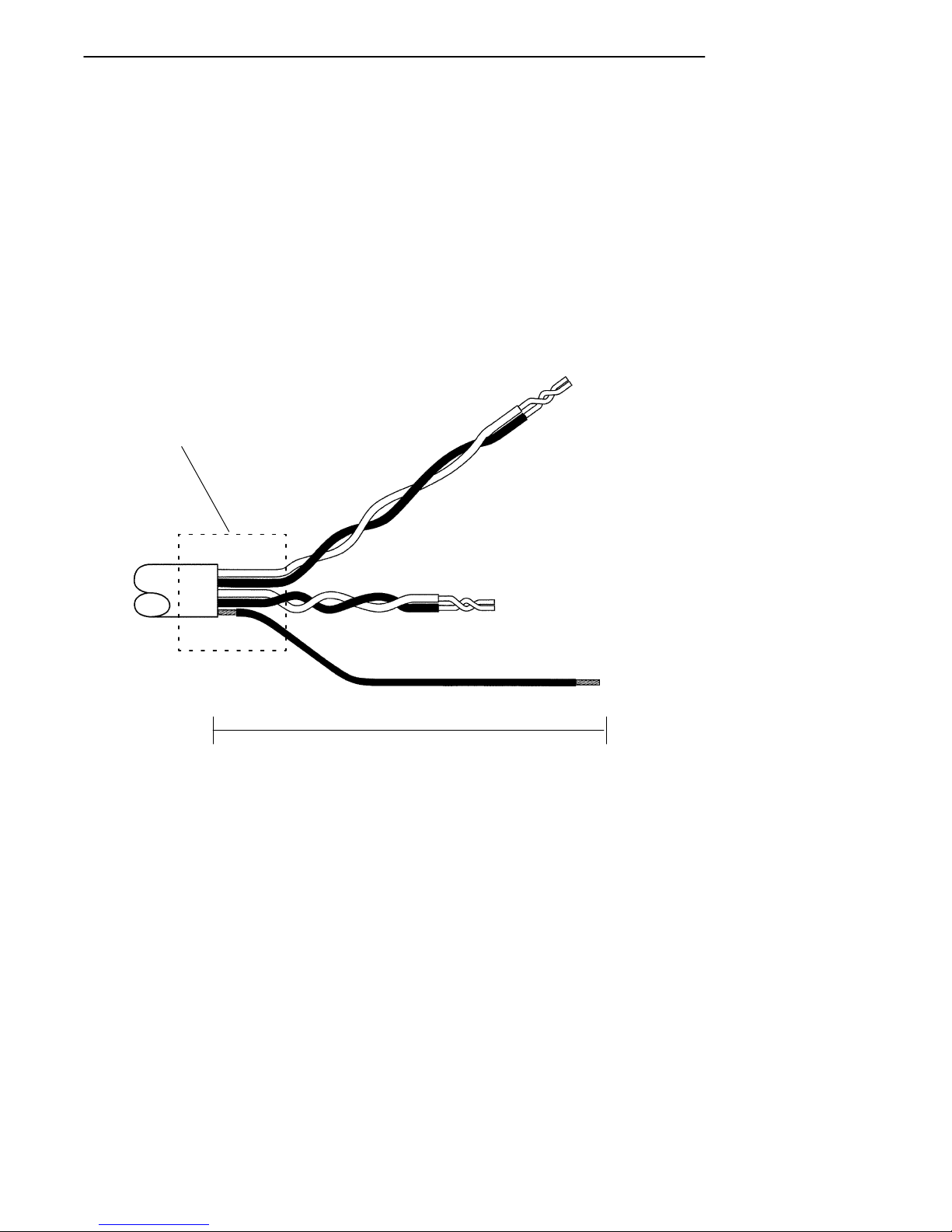
Cutand Stripthe PowerCable
1.Cut thepower cablenearthepowersource orbattery.
2.Stripthecablejacketback12--14 inches.
3.Slideheatshrinktubingover cablejacket.
4.Strip1/4”ofinsulationfromindividualwires.
5.Twist thewhiteandgreen(negative)wirestogether.
6.Twist theredandblack(positive)wirestogether.
7.Twist theshieldwireandslidethe1/8”heatshrink
tubingontoit.
Input
Power
Cable
Figure 2-1
Cutand StripCableEnds
Heatshrinktubing
Redand Black Wires
(positive)
Greenand WhiteWires
(negative)
Shieldwirew/heatshrink applied
StriptheCableJacket12--14 inches
NOTE:See “Note”on page 2-5wheninstalling on gas-poweredvehicles.

SECTION 2"Installation Procedures
2-8VehiclePowerSupplyInstallation Guide
Heatshrink Tubing
Thiskitcontainsa6inchlengthof3/8”heatshrinktubing
whichyouwill cutintothree pieces,anda12inchlengthof
1/8”heatshrinktubingfortheshieldwire.Tubingmustbe
inplacebefore terminatingwire ends.Crimpterminalrings
andfuseholderends,thenpositionall heatshrinktubingin
thelocations shown.Useaheatgun toshrinktubing.
1.Greenand Whitetwisted pair
2.Redand Black twisted pair
3.Shieldwire,twisted
Figure 2-2
Heatshrink Locations
b
1
2
3
b
3/8”
b
b
3/8”3/8”
Arrowsdenote heatshrink
locationsand diameter.
1/8”
b
b
NOTE:See “Note”on page 2-5wheninstalling on gas-poweredvehicles.

SECTION 2"Installation Procedures
VehiclePowerSupplyInstallation Guide 2-9
Preparethe CableEnds
Bothlarge(3/8inch)andsmaller(#10)terminalringsare
providedforyourselectionanduseinthefollowingsteps.A
small (#10)terminalringshouldbecrimpedtotheshield
wireandthenfastenedtovehiclechassisground.
1.Crimpaterminalringontothewhite-greentwisted
pair(negative)ofwires.
2.Cut thered-blacktwisted pair(positive)ofwiresat the
midpoint.Stripexposedends.
3.Positionshortlengthsofheatshrinktubingasinindi-
catedinFigure2-2.
4.Crimpthefuseholdertothepositivewiresfrom the
cable.
5.Shortentheremainingpositivewires(pigtail)ifde-
siredand positionashortlengthofheatshrinktubing
ontothispigtail.
6.Crimpthispositivepigtail tothefuseholder.
7.Securelycrimpaterminalringto endofthepositive
pigtail from thefuseholder.
8.Slideheatshrinkover crimps,shrinkwith heatgun.
PowerSource Connections
Thenextfourpages showyoutheintended purpose ofnuts,
bolts,andwashersthatareincludedinthiskitifyouwill be
connectingthepower cabledirectlytoavehiclebattery.
Additionalhardwareisnotprovidedinthiskitforconnecting
thepower cableto othervehiclepowersources.Refertothe
manufacturer’stechnicalmanualforthevehicleifnecessary.

SECTION 2"Installation Procedures
2-10 VehiclePowerSupplyInstallation Guide
Direct toBatteryConnections
Side-mounted BatteryTerminals
1.Removebothterminalscrewsfrom thevehiclebattery.
2.Screwa 3/8”nutasfarasitwill go ontoa 3/8”X1-1/2”
boltfurnishedinkit.
3.Slipa 3/8”washerontothebolt.
4.Slidethepositive(fuseholder)terminalringontothe
positivebatteryterminalbolt.
5.Slipasecond3/8”washerontothebolt.
6.Slidethevehiclepositivebatterycable ontothebolt.
7.Threadtheboltassembly(steps1--6,above)intothe
positivebatteryterminal.Tightentheboltuntil itbot-
tomsoutbutdonotovertightenthebolt.
8.Tightenthenutsecurelyagainst thewashersand
cables.
9.Useself-tappingscrewandaflatwashertoconnect
shieldwiretovehiclechassisground.
Repeatsteps2through 8 forthenegative (white--green pair)wirefromtheinput
powercable,hooking up thenegative cablestothenegative (--)batteryterminal.
NOTE:See “Note”on page 2-5wheninstalling on gas-poweredvehicles.

SECTION 2"Installation Procedures
VehiclePowerSupplyInstallation Guide 2-11
1.Bolt
2.Nut
3.Vehiclebattery
4.Vehiclebattery cable
5.Fuse holder
6.Washers
1
Figure 2-3
Side-MountBatteryTerminals
2
6
3
4
5
NOTE:See “Note”on page 2-5wheninstalling on gas-poweredvehicles.
This manual suits for next models
1
Table of contents
Other Intermec Power Supply manuals


